.
BP Apollo 3000 Dispenser
Supply & Installation Procedure
Stage 1 Under Ground Sump Enclosure Installation
Components supplied by PEC to site.
Components include; Sump Enclosure Box Assy with, Cable Duct, Delivery Ducts with Internal Delivery
Pipe Assys. fitted.
Bulkhead Seals (Pre fitted into Sump Enclosure)
Sump Box Lid with Handles
Sump Cover & Sub-frame, Securing Screws & divider skirt fitted
Main Wiring Looms & Junction Box (Fitted into Sump Box)
Float Switch & Cable Assy (Fitted to Mtg. Brkt.)
Installation Procedure
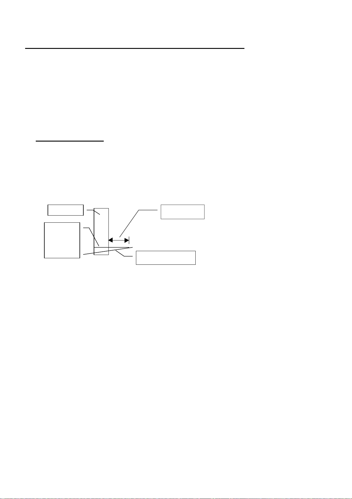
•Establish proposed/final Forecourt ground level, mark this point on Column.
•Install Sump Box Enclosure into correct position below proposed ground level as shown in figs 1,2 &3
•Ensure Pipe Delivery Ducts protrude 50mm above ground level & 20mm proud of Column. Also
ensure top edge of Sump is 60 mm below ground & level. End face of Enclosure is 300 mm out from
Column (Fig 1) Note Ensure underside of Enclosure is firmly packed to prevent Enclosure sinking or
moving.
•Pack filling material around Sump Enclosure approximately up to a point just under Bulkhead Fittings,
this is to ensure Enclosure does not move while further work is being conducted.
•Plug or cover Pipe Delivery Ducts to stop any foreign matter entering.
•Install Main Product Feed Lines Into Sump (refer Apollo Hydraulic & Intrinsic Connections Pg. 27 NZ
& Pg. 28 Aus.) for correct positioning etc. (Refer page 09 for Feed Line installation Details)
•T connector terminated with ¾” Ball Valve & ¾- ¾” BSP Elbow
B22 22 12 12
•Ensure Ball Valves Face toward BOTTOM of Sump no more than 10 dec. off Vertical,
with lever side towards Column
•Check & tighten all Seals
•Check for Leaks
•Recheck Sump position in relation to Column & Forecourt Surface as per Refer Figs. 1, 2 & 3.
•Secure Pipe Delivery Ducts & Main Feed Lines into position to prevent movement while Back Filling.
•Temporarily pack internal side walls of Sump using timber or similar to eliminate walls collapsing
inwards during back filling.
•Install all Servicing Cabling & Pipe work as required for operation. Ensure all services are positioned
correctly to clear Vent Box, Head Mtg. & GRP Cladding etc. Ref. fig 2 & 3 for details.
•Recheck Seals & Sump Position.
•Backfill to cover Feed Lines & secure Sump Enclosure position.
•Position & Secure Sump Lid Frame (Centralise around Sump Box) check with Forecourt Level (Note
Frame & cover can be raised locally above general Forecourt level if required to prevent water
ingress.(Possibly 10 –20 mm above general Forecourt level
•Back Fill & Compact to within 150 mm of Forecourt surface, 30 –50 mm up Skirting walls
•Concrete Forecourt as per Site requirements.