IES Keywatt 24 Wallbox User manual

User Manual
Keywa 24 Wallbox
www.ies-synergy.com
DUM016055-EN_V003d

www.ies-synergy.com
User Manual DUM016055-EN
2
The information provided in this documentation contains general descriptions and/or technical characteristics
of the performance of the products contained herein. This documentation is not intended as a substitute for
and is not to be used for determining suitability or reliability of these products for specific user applications. It
is the duty of any such user or integrator to perform the appropriate and complete risk analysis, evaluation and
testing of the products with respect to the relevant specific application or use thereof. Neither IES Synergy nor
any of its affiliates or subsidiaries shall be responsible or liable for misuse of the information contained herein.
If you have any suggestions for improvements or amendments or have found errors in this publication, please
notify us.
You agree not to reproduce, other than for your own personal, noncommercial use, all or part of this document
on any medium whatsoever without permission of IES Synergy, given in writing. You also agree not to establish
any hypertext links to this document or its content. IES Synergy does not grant any right or license for the per-
sonal and noncommercial use of the document or its content, except for a non-exclusive license to consult it on
an “as is” basis, at your own risk. All other rights are reserved.
All pertinent state, regional, and local safety regulations must be observed when installing and using this prod-
uct. For reasons of safety and to help ensure compliance with documented system data, only the manufacturer
should perform repairs to components.
When devices are used for applications with technical safety requirements, the relevant instructions must be
followed.
Failure to use IES Synergy software or approved software with our hardware products may result in injury,
harm, or improper operating results.
Failure to observe this information can result in injury or equipment damage.
© 2020 IES Synergy. All rights reserved.

www.ies-synergy.com
User Manual DUM016055-EN
3
Table of content
1. Safety notes 4
Notice 4
Please note 4
2. About the manual 5
Purpose of this manual 5
Document scope 5
Related documents 5
User comments 5
3. General Safety instructions 6
4. Overview 7
WBG3 external view 7
WBG3X external view 8
5. Specification 9
Main supply 9
Technical specification 10
6. Operating instructions 14
Start a Vehicle Charge Session 14
Stop a Vehicle Charge Session 14
Emergency Stop 14
7. Utilization 15
Human/Machine interface (HMI) 15
Charge selection 16
User identification 17
EV connection 17
EV communication 18
EV charge 19
End of charge 20
Other messages 23
Errors 24
www.ies-synergy.com
User Manual DUM016055-EN
4
1. Safety notes
Notice
Read these instructions carefully, and look at the equipment to become familiar with the device before trying
to install, operate, or maintain it. The following special messages may appear throughout this documentation
or on the equipment to warn of potential hazards or to call attention to information that clarifies or simplifies
a procedure.
The addition of this symbol to a Danger hazard statements indicates that an electrical hazard
exists, wich result in personal injury if the instructions are not followed.
This is the safety alert symbol. It is used to alert you to potential personnal injury hazards. Obey
all safety messages that follow this symbol to avoid possible injury or death.
IDANGER
DANGER indicates an imminently hazardous situation which, if not avoided, will result in death or seri-
ous injury.
IWARNING
WARNING indicates a potentially hazardous situation which, if not avoided, can result in death or seri-
ous injury.
ICAUTION
CAUTION indicates a potentially hazardous situation which, if not avoided, can result in minor or mod-
erate injury.
NOTICE
NOTICE is used to address practices not related to physical injury.
Please note
Electrical equipment should be installed, operated, serviced, and maintained only by qualified personnel. No
responsibility is assumed by IES Synergy for any consequences arising out of the use of this material.
A qualified person is one who has skills and knowledge related to the construction and operation of electrical
equipment and its installation, and has received safety training to recognize and avoid the hazards involved.
www.ies-synergy.com
User Manual DUM016055-EN
5
2. About the manual
Purpose of this manual
Technical documentaon is an integral part of a product. Unl it is disposed of, always keep the technical
documentaon close to the unit at hand, as it contains important informaon. Provide technical documentaon
to the person concerned if you sell, assign or lend the product.
This guide aims to provide informations needed for the use of the Keywatt 24 mono (G3) and multi-standard
(G3X). This guide must be read in integrality with others related documents. This guide is intended for users of
the charging stations.
Document scope
This guide concerns the following charging station:
• P/N: WBG3 3PN CHARGER
• P/N: WBG3 3P CHARGER
• P/N: WBG3 1PN CHARGER
• P/N: WBG3X_TRI S 3PN CHARGER
• P/N: WBG3X_TRI 3PN CHARGER
• P/N: WBG3X_BI 3PN CHARGER
• P/N: WBG3X_BI 3P CHARGER
• P/N: WBG3X_BI 1PN CHARGER
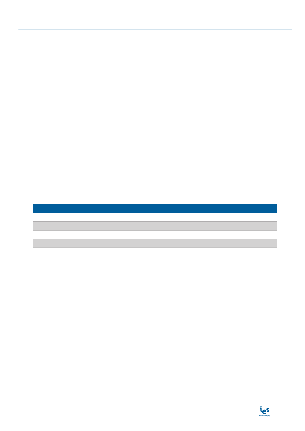
Related documents
Document title Product Reference
Installation Manual WBG3 DIM016055-EN
Installation Manual WBG3X DIM016197-EN
User Manual WBG3/G3X DUM016055-EN
Service Manual WBG3/G3X DMM016055-EN
User comments
We invite you to write us to communicate any inaccuracies or omissions, or to make general comments or sug-
gestions regarding the quality of this manual.
www.ies-synergy.com
User Manual DUM016055-EN
6
3. General Safety instructions
NOTICE
SAVE THIS MANUAL
• To ensure proper and safe operation, please read these user instructions carefully and
keep them for future reference.
• This manual contains important instructions for the DC quick charger that shall be followed
during installation, operation and maintenance of the unit.
• This equipment shall be installed, adjusted, and serviced by qualified electrical personnel
familiar with the construction and operation of this type of equipment and associated
hazards.
• The locking key, supplied with unit, should be kept in a secure and known location by an
individual that has read and understands the content of this manual.
• Do not open the front cover at any time while input power is present.
• Do not operate the unit while the cabinet door is opened or unlocked.
Failure to follow these instructions may result in death, serious injury or equipment
damage.
IWARNING
RISK OF ELECTRIC SHOCK, INJURY, AND/OR BURNING
• Only qualified, trained and authorized people will repair, replace or adjust this equipment.
• Make sure the AC input breaker is OFF and measures 0V after the breaker.
• Do not use this product if the cables (input or output) are frayed, have damaged insulation
or any other signs of damage.
• Do not use this product if the enclosure or the EV connectors are broken, cracked, opened
or show any other indication of damage.
• This equipment employs parts, such as switches and relays, that tend to produce arcs or
sparks and therefore, when used in a garage, locate in a room or enclosure provided for the
purpose or not less than 500mm (18 inches) above the floor.
Failure to follow these instructions can result in death or serious injury
ICAUTION
RISK OF DAMAGE TO THE TERMINAL
• Do not use this product if the cables (input or output) are frayed, have damaged insulation
or any other signs of damage.
• Do not use this product if the enclosure or the Electrical Vehicle Supply Equipment (EVSE)
connectors are broken, cracked, opened or shows any other indication of damage.
• Do not use a cord extension set or second cable assembly in addition to the cable assembly
for the connection of the EV to the EVSE.
• This equipment is not intended for use in residential environments and may not provide
adequate protection to radio reception in such environments.
Failure to follow these instructions may result in serious injury or equipment damage.
www.ies-synergy.com
User Manual DUM016055-EN
7
4. Overview
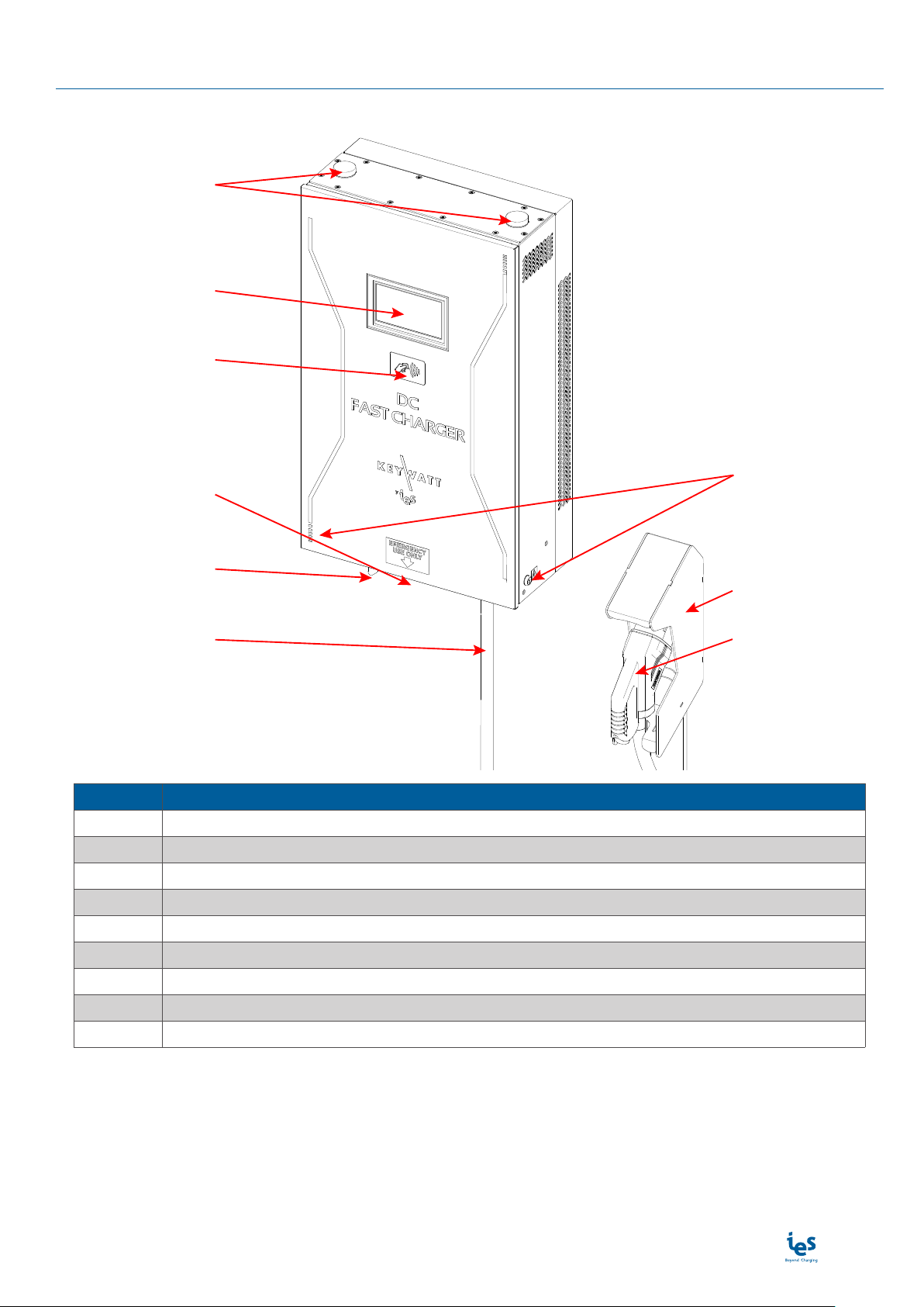
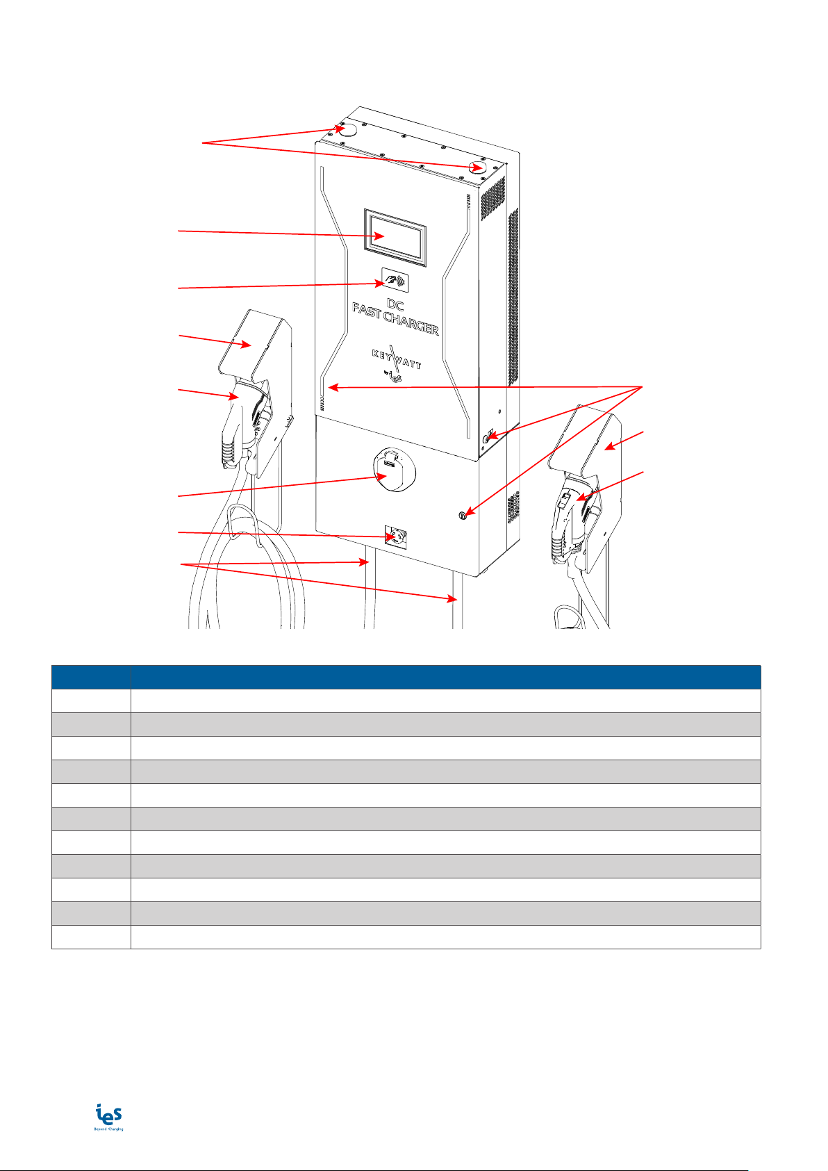
WBG3 external view
❶
❷
❸
❹
❺
❻
❼
❽
❾
Position Description
1 Antennas
2 7” touchscreen display
3 RFID reader
4 Emergency Stop button
5 Input cable
6 Output cable
7 Key locker
8 Connector support
9 Output DC connector
Note: May change depending on version or technical modification
www.ies-synergy.com
User Manual DUM016055-EN
8
WBG3X external view
❶
❷
❸
❹
❺
❻
❾
❿
❽
⓫
❼
Position Description
1 Antennas
2 7" touchscreen display
3 RFID reader
4 Connector support
5 Output Combo 2 DC connector
6 AC socket outlet Type 2 S
7 Emergency Stop button
8 Output cable
9 Key locks
10 Connector support
11 Output CHAdeMO DC connector
Note: May change depending on version or technical modification
www.ies-synergy.com
User Manual DUM016055-EN
9
5. Specification
Main supply
The charging station can be connected to several mains supplies as detailed on following tables.
Mains supplies 3-phase L1/L2/L3+ N + PE 3x400VAC (phase to phase)
Mains 3-phase voltage range VAC 400 VAC ± 10%
Earthed electrical system TT; TN
Frequency range f 50 Hz ± 10%
Nominal input current IAC
40-32A (mono-std)
Nom38A (bi-std)
70A (tri-std)
Maximum input current IAC
45A (mono/bi-std) Max
78A (tri-std)
Power Factor PF 0,99 Nom
Efficiency ɳ95 % Max
Harmonic current @ nominal network voltage THDi < 13 % Max
Mains supplies 3- phase L1/L2/L3+ PE 3x208-240VAC
Mains 3-phase voltage range VAC 208-240 VAC ± 10%
Earthed electrical system
TT; TN; IT
IWarning for WBG3X: IT earthed electrical
system prohibited for AC charging
Frequency range f 50 Hz ± 10%
Nominal Input current IAC 72-63A Nom
Maximum Input current IAC 80A Max
Power Factor PF 0,99 Nom
Efficiency ɳ95 % Max
Harmonic current @ nominal network voltage THDi < 13 % Max
Mains supply single-phase L + N + PE 1x220-240VAC
Mains single-phase voltage range VAC 220-240 VAC ± 10%
Earthed electrical system TT; TN
Frequency range f 50 Hz ± 10%
Nominal Input current IAC 123-112A Nom
Maximum Input current IAC 140A Max
Power Factor PF 0,99 Nom
Efficiency ɳ95 % Max
Harmonic current @ nominal network voltage THDi < 13 % Max

www.ies-synergy.com
User Manual DUM016055-EN
10
Technical specification
Internal AC input protection
Inrush current limitation per phase IINRUSH LIMIT < 3 x IAC Max
Rated Current Fuse (per module) IBREAK Rating 80A typ
Breaking capacity of fuses IBREAK Capacity 80 000A Max
Max earth leakage current ILEAKAGE < 3,5 mA Max
Emergency button connection Yes
Overvoltage category (IEC60664-1) III
Insulation protection Class (IEC60664-1) Class I
DC Output
COMBO 2 output voltage VDC_max 530 VDC Max
VDC_min 200 VDC Min
CHAdeMO output voltage VDC_max 500 VDC Max
VDC_min 150 VDC Min
Output current IDC_max 65A (1)(2) Max
IDC_min 1,5A Min
Max Output Power POUT 24kW Max
Output connector (charging station side) Permanent mounting
Car Plug connector Plug #1(5) COMBO 2(5)
Plug #2(5) CHAdeMO(5)
Output cable length Meters 3,5 (5,2 in option) -10/+0%
AC output (for WBG3X_TRI 3PN only)
AC Output voltage VAC_nom 400 VAC ± 10%
AC Output current IAC_max 32 A Max
Max Output Power POUT 22 kVA Max
Car Plug socket Plug #3 AC type 2 S
Type of connection Case “B” connection (mode3)
Detachable cable
Internal DC output protection
Hardware and software short circuit protection Yes
Software and Hardware over voltage protection adjustable +10% max
Over temperature protection - 70 °C
Reverse polarity protection Yes
DC output Contactor Yes (2 poles)
Rated Current Fuse (output) IFUSE 125 A
Galvanic isolation Vinput / output
4800 (G3)
5200 (G3X) VDC
Max time for DC line discharge < 60V T<60V 1 s
Internal AC output protection (WBG3X only)
Inrush current 230A during 100 µs
30A during following second
Short circuit Socket I²t A²s 75 000
Circuit breaker for AC circuit 50A curve C

www.ies-synergy.com
User Manual DUM016055-EN
11
Embedded Insulation device
Response time (tan) < 3sec. for asymmetrical fault
< 62sec. for symmetrical fault
Self test time At power on and every 60s during charge
Internal resistance Ri of the measuring circuit
1.5Mohms permanent
750Kohms continuous measurement
300Kohms during simultaneous switching measurement
Measurement method Continuous and switching measurement resistor method
Measuring current Im < 1,4mA at RF=0
Measurement range (Ran) 20Kohms…300Kohms
Relative uncertainty ±15%
Line L+/L- Voltage (Un) DC 150V…530V
System leakage capacity Ce ≤ 1µF : response value (Ran) and time (tan) are not guar-
anteed for capacity above 1µF
Parallelization
IWarning: Do not connect the insulation monitor de-
vice (IMD) in parallel !!
Response value (Ran) and time (tan) are not guaranteed.
Radio Frequency characteristics
The equipment module is designed to provide customers with global network coverage on the connec-
tivity of UMTS/HSPA+, and it is also fully backward compatible with the existing EDGE and GSM/GPRS
networks.
Frequency band (MHz) Output power (dBm)
Tx Rx Min Max
GSM850/EGSM900 (GMSK) 880-915 925-960 5 ±5dB 33 ±2dB
GSM850/EGSM900 (8-PSK) 880-915 925-960 0 ±5dB 27 ±3dB
DCS1800/PCS1900 (GMSK) 1710-1785 1805-1880 0 ±5dB 30 ±2dB
DCS1800/PCS1900 (8-PSK) 1710-1785 1805-1880 0 ±5dB 26 ±3dB
WCDMA B1/B2/B4-B6/B8/B19 B1/B2/B4-B6/B8/B19 <-49 24 +1/-3dB
LTE-FDD
B1-B5/B7/B8/B12/
B13/B18-B20/B25/
B26/B28
B1-B5/B7/B8/B12/
B13/B18-B20/B25/
B26/B28
<-39 23 ±2dB
LTE-TDD B38-B41 B38-B41 <-39 23 ±2dB
RFID reader characteristics
To start a charge, users must swipe a contactless RFID card across the card reader.
Frequency bands 13.56 Mhz
Output power -5dBuA/m@3m
General & dimensions
External dimensions (mm) H x W x D 860 x 507 x 250 mm (G3)
1225 x 507 x 250 mm (G3X)
Weight (without cable, or bracket) kg 66kg (G3)
93kg (G3X) Max
Type of installation Wall / Pedestal mounting
Fixation points 8 screws
Protection type (EN60529) IP55

www.ies-synergy.com
User Manual DUM016055-EN
12
General & dimensions
Cooling systems Heatsink with forced air flow by fans IP55
without air filter
Noise (1m, all direction) Db(A) 65dbA (1m)
Climatic & Environment constraints
Operating temperature (with derating) -25°C to +55°C(3)
Storage temperature -25°C to +60°C
Relative humidity RH 10% to 95%
Installation altitude Alt 2 000m Max
Norms & standards
Radio Equipment Directive (RED) 2014/53/EU
Efficient use of Radio Spectrum (RED)
ETSI EN 301 511 V12.5.1
ETSI EN 301 908-1 V11.1.1
ETSI EN 301908-2 V11.1.2
ETSI EN 301908-13 V11.1.2
ETSI EN 300 330 v2.1.1
Electric vehicle conductive charging system
Part 1: General requirement IEC 61851-1
Electric vehicle conductive charging system
Part 22: AC Electric vehicle charging station IEC 61851-22
Electric vehicle conductive charging system
Part 23: DC Electric vehicle charging station IEC 61851-23
Electric vehicle conductive charging system
Part 24: Digital communication between a DC charging
station and an EV for control of DC charging
IEC 61851-24
Electromagnetic compatibility (EMC)
IEC 61851-21-2 (for G3 only)
EN 61000-3-11 (for G3X only)
EN 61000-3-12 (for G3X only)
EN 61000-6-2 (for G3X only)
EN 61000-6-4/A1 (for G3X only)
EN 301489 v2.2.0 (for G3X only)
EN 301489-17 V3.2.0:2017 (for G3X only)
Insulation Monitor Device (IMD) IEC 61557-1
IEC 61557-8
RoHS 2015/863/EU (for G3 only)
2011/65/EU (for G3X only)
Declaration of conformity CE(4) Yes
EV Ready (for G3X only) Compliant
(1) Max output current will be adapted versus maximum carrying current of the vehicle plug.
(2) Output current can be even reduced with the power derating versus temperature.
(3) Potential derating above 35°C.
(4) CE marking affixed on the product attest the conformity of the product with applicable requirements of relevent Community har-
monization legislation.
(5) On Wallbox G3, you only have one Combo or CHAdeMO connector.
www.ies-synergy.com
User Manual DUM016055-EN
13
Compliance
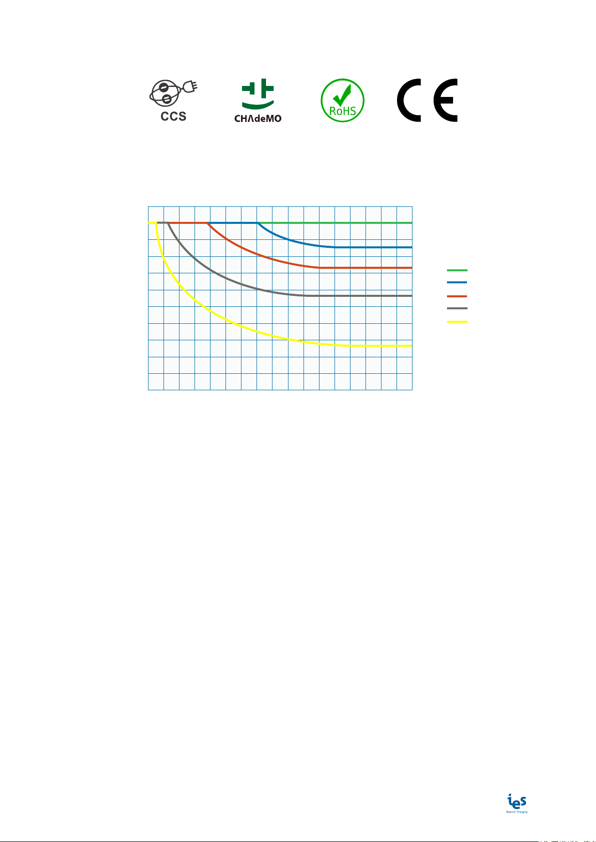
Derating
As a direct correlation exists between the current and ambient temperature a derating curve is provided for all
charging station.
Minutes before derating
@ VOUT=370VDC & IOUT=65A
0
10
0 10 20 30 555 15 25 5035 60 7540 65 8045 70 85
20
30
40
50
60
70
90
80
100
35°C
40°C
45°C
50°C
55°C
Max Power (%)

www.ies-synergy.com
User Manual DUM016055-EN
14
6. Operating instructions
Start a Vehicle Charge Session
Before starting a charge session:
Ensure the unit is properly assembled in accordance with the assembly instructions before it is used
You must have a RFID Card activated on backend server or being connected to backend App.
Note: The RFID card MIFARE 1k is recommended.
1. A) Swipe an activated RFID card once across the card reader
or
B) Remotely start the charge through an application linked to the backend
2. A) The unit will beep once indicating the card swipe was successful
B) Wait for display indication
3. The display will show if the charge has been authorized
4. The display will instruct the user when to plug into the vehicle
5. Plug the connector firmly into the vehicle. The latch should click
6. Observe the display and charging will begin once the car acknowledges the charger
Stop a Vehicle Charge Session
The charger will automatically stop once charging is completed. Fast charging will occur up to 80% of the vehi-
cles battery state of charge. The charger will adjust its output according to the demands of the vehicle, ambient
temperatures and other factors.
To stop charging before the end of the charging cycle follow these steps:
1. A) With the same card that the session was initiated with, swipe over the card reader
or
B) Remotely stop the charge through an application linked to the backend
2. The display will indicate that the session is ending
3. Once the session has ended the vehicle will unlock the connector. A click may be heard at the vehicle/con-
nector
4. Once unlocked, remove it from the vehicle charging inlet
5. Return the connector to the dock on the charging station
Emergency Stop
In the event of an emergency the Emergency Stop button may be depressed to instantly stop charging.
To emergency stop follow these steps:
1. Depress the emergency stop button bellow the charger
2. The display will show the text “Error occurred: 0x02 Emergency stop was launched. Please unplug your
vehicle and check the emergency button is released.”
3. Unplug the connector from the vehicle
To reset after emergency stop rotate the button clockwise until it pops outward. After a self-test the display will
remove the emergency stop message and will be ready for a new session.

www.ies-synergy.com
User Manual DUM016055-EN
15
7. Utilization
Human/Machine interface (HMI)
Color code
Fixed Blinking
Available Preparing/Finishing Charging Unavailable Error
Note: Applicable in COMBO, CHAdeMO and AC.
Charger states
• Available: Connector available
• Preparing: Charge preparation
• Finishing: Charge ending or ended but connector still connected to the vehicle
• Unavailable: Connector unavailable
• Error: An error has occured
www.ies-synergy.com
User Manual DUM016055-EN
16
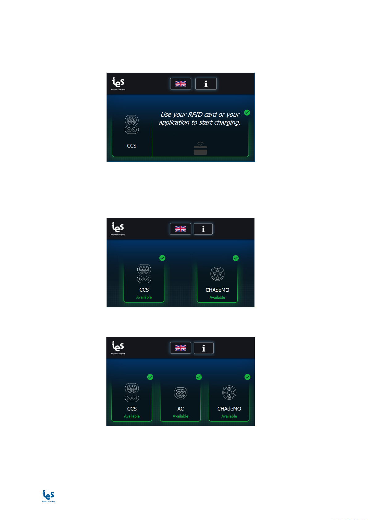
Charge selection
Depending on your configuration, the Wallbox offers up to 3 means of connection to the vehicle.
Mono-Standard version
Note: Applicable in COMBO and CHAdeMO
Bi-Standard version
The choice of the type of charge is made by selecting the right logo directly on the touch screen.
Tri-Standard version

www.ies-synergy.com
User Manual DUM016055-EN
17
User identification
Once the type of charge selected, an identification screen is displayed.
When an user wants to recharge the electrical vehicle, there are 2 ways to identify on the charging station:
• to swipe an activated RFID card once across the card reader, or
• to remotely start the charge through an application linked to the supervision tool.
Note: Applicable in COMBO, CHAdeMO and AC
Note: Applicable in COMBO, CHAdeMO and AC
EV connection
The charging station invites the user to connect the EV with the following screen:
Note: Applicable in COMBO, CHAdeMO and AC

www.ies-synergy.com
User Manual DUM016055-EN
18
EV communication
Before starting a charge, the charging station communicates with the electrical vehicle to collect information.
All these steps are necessary to adapt the charging station parameters to the electrical vehicle.
Note: Applicable in COMBO, CHAdeMO and AC
Note: Applicable in COMBO and CHAdeMO

www.ies-synergy.com
User Manual DUM016055-EN
19
EV charge
Combined Charging System (CSS) and CHAdeMO
During the charge of the electrical vehicle, the charging station shows the charge informations (time since the
start of charging, charged energy and percentage of charge).
Note: Applicable in COMBO and CHAdeMO
AC (for WBG3X only)
During the charge of the electrical vehicle, the charging station shows the charge informations (time since the
start of charging and charged energy).

www.ies-synergy.com
User Manual DUM016055-EN
20
End of charge
After completing the charge of the electric vehicle, the charging station performs multiple control steps before
disconnecting the vehicle.
Combined Charging System (CSS)
When the COMBO protocol is used, the user can unplug the vehicle once the charge is done.
Other manuals for Keywatt 24 Wallbox
1
This manual suits for next models
8
Table of contents
Other IES Batteries Charger manuals


