IES Wallbox G3 User manual
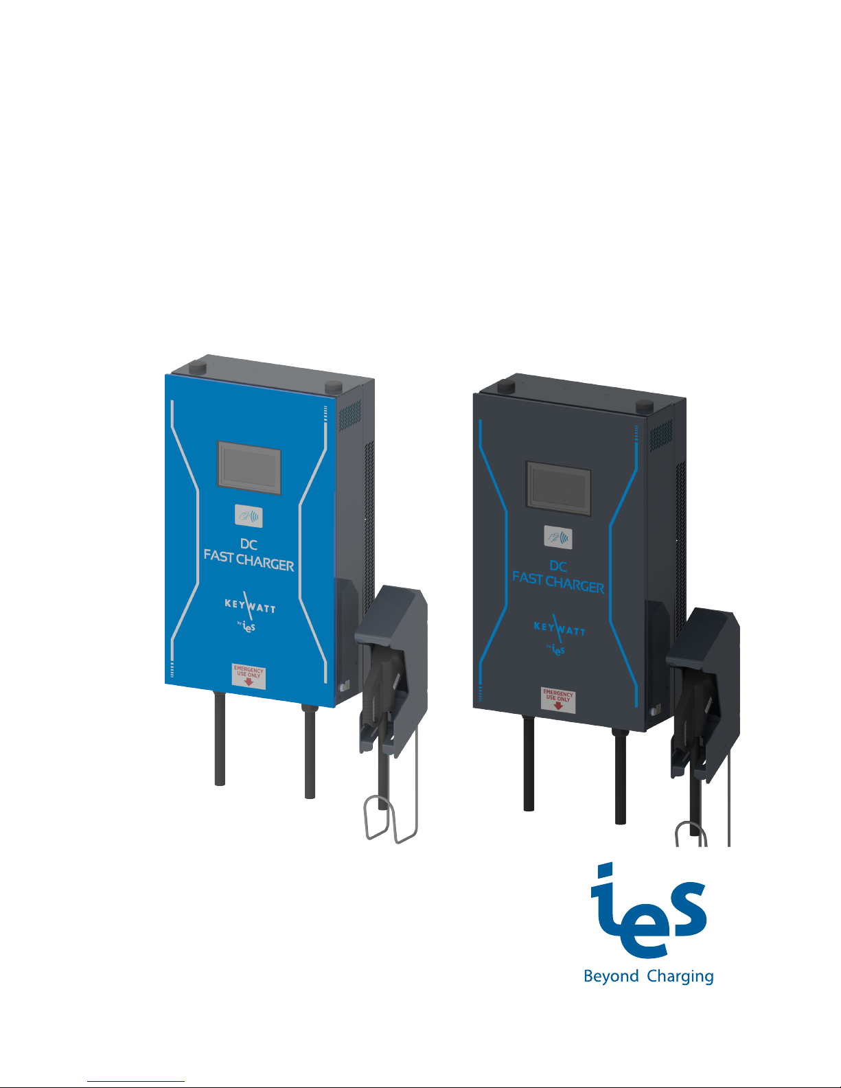
Installation Manual
for Wallbox G3
www.ies-synergy.com
DIM016055-EN_V002

www.ies-synergy.com
Installation Manual DIM016055-EN
2
The information provided in this documentation contains general descriptions and/or technical characteristics
of the performance of the products contained herein. This documentation is not intended as a substitute for
and is not to be used for determining suitability or reliability of these products for specific user applications. It
is the duty of any such user or integrator to perform the appropriate and complete risk analysis, evaluation and
testing of the products with respect to the relevant specific application or use thereof. Neither IES Synergy nor
any of its affiliates or subsidiaries shall be responsible or liable for misuse of the information contained herein.
If you have any suggestions for improvements or amendments or have found errors in this publication, please
notify us.
You agree not to reproduce, other than for your own personal, noncommercial use, all or part of this document
on any medium whatsoever without permission of IES Synergy, given in writing. You also agree not to establish
any hypertext links to this document or its content. IES Synergy does not grant any right or license for the per-
sonal and noncommercial use of the document or its content, except for a non-exclusive license to consult it on
an “as is” basis, at your own risk. All other rights are reserved.
All pertinent state, regional, and local safety regulations must be observed when installing and using this prod-
uct. For reasons of safety and to help ensure compliance with documented system data, only the manufacturer
should perform repairs to components.
When devices are used for applications with technical safety requirements, the relevant instructions must be
followed.
Failure to use IES Synergy software or approved software with our hardware products may result in injury,
harm, or improper operating results.
Failure to observe this information can result in injury or equipment damage.
© 2018 IES Synergy. All rights reserved.

www.ies-synergy.com
Installation Manual DIM016055-EN
3
Table of content
1. Safety notes 5
Notice 5
Please note 5
2. About the manual 6
Purpose of this manual 6
Document scope 6
Related documents 6
User comments 6
3. General Safety instructions 7
4. Overview 8
External view 8
Internal door view 9
Internal view- upper level 10
Internal view- lower level 11
5. Specification 12
Main supply 12
3-phase P1/P2/P3 + N + GND 3x380-480VAC 12
3- phase P1/P2/P3 + GND 3x208-240VAC 12
Single-phase P + N + GND 1x220-240VAC 12
3-phase P1/P2/P3 + N + GND 3x380-400VAC with power metering(1) 12
Technical specification 13
Compliance 15
Derating 15
6. Handling and storage instructions 16
Storage 16
Transport 16
Equipment Handling 16
7. Installation 17
Installation rules 17
Unscrew lid of crate 18
Unpacking Wallbox 18
Unpacking 18
Open the side door 19
Unlock Wallbox bracket 19
Remove Wallbox bracket 20
Wall mounting 21
Install Wallbox bracket 21
Install Wallbox 22
Lock the Wallbox on its bracket 22
Close the side door 23
Connector’s holster installation 24
Connector holster installation 24
Hold the connector on holster 25
Switch off external power supply 26
Electrical connection 26
Checking the Electrical Requirements 26
Grounding Instructions 26
Open the door 27
Remove Input plate with cable gland 27

www.ies-synergy.com
Installation Manual DIM016055-EN
4
Pass the power cable 28
AC input configuration 29
3-phase P1/P2/P3 + N + GND 3x380-480VAC 30
3- phase P1/P2/P3 + GND 3x208-240VAC 30
Single phase P + N + GND 1x220-240VAC 31
3-phase P1/P2/P3 + N + GND 3x380-480VAC with power metering 31
Close input plate with cable gland 32
Close the door 32
Switch on external power supply 33
8. Commissioning 34
SIM card 34
Customer SIM card installation 34
First booting 34
Booting errors 35
Power limitation 35
9. Protecting the environment 36
Recycling Packaging 36
End-of-Life Recycling 36

www.ies-synergy.com
Installation Manual DIM016055-EN
5
1. Safety notes
Notice
Read these instructions carefully, and look at the equipment to become familiar with the device before trying
to install, operate, or maintain it. The following special messages may appear throughout this documentation
or on the equipment to warn of potential hazards or to call attention to information that clarifies or simplifies
a procedure.
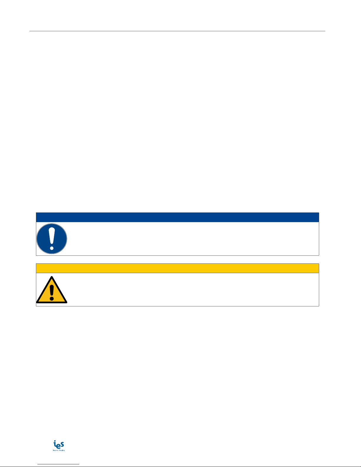
The addition of this symbol to a Danger hazard statements indicates that an electrical hazard
exists, wich result in personal injury if the instructions are not followed.
This is the safety alert symbol. It is used to alert you to potential personnal injury hazards. Obey
all safety messages that follow this symbol to avoid possible injury or death.
IDANGER
DANGER indicates an imminently hazardous situation which, if not avoided, will result in death or seri-
ous injury.
IWARNING
WARNING indicates a potentially hazardous situation which, if not avoided, can result in death or seri-
ous injury.
ICAUTION
CAUTION indicates a potentially hazardous situation which, if not avoided, can result in minor or mod-
erate injury.
NOTICE
NOTICE is used to address practices not related to physical injury.
Please note
Electrical equipment should be installed, operated, serviced, and maintained only by qualified personnel. No
responsibility is assumed by IES Synergy for any consequences arising out of the use of this material.
A qualified person is one who has skills and knowledge related to the construction and operation of electrical
equipment and its installation, and has received safety training to recognize and avoid the hazards involved.
www.ies-synergy.com
Installation Manual DIM016055-EN
6
2. About the manual
Purpose of this manual
Technical documentation is an integral part of a product. Until it is disposed of, always keep the technical docu-
mentation close to the unit at hand, as it contains important information. Provide technical documentation to
the person concerned if you sell, assign or lend the product.
This guide aims to provide informations needed for installation and end-of life of the charging station IES Wall-
box G3. This guide must be read in integrality with others related documents. This guide is intended for quali-
fied personnel to install on the charging stations.
Document scope
This guide concerns the following charging station :
• Art/N : WBG3 3PN Charger
• Art/N : WBG3 3P Charger
• Art/N : WBG3 1PN Charger
• Art/N : WBG3 3PN Charger with power metering
Related documents
Document title Reference
Installation Manual DIM016055-EN
User Manual DUM016055-EN
Service Manual DMM016055-EN
User comments
We invite you to write us to communicate any inaccuracies or omissions, or to make general comments or sug-
gestions regarding the quality of this manual.

www.ies-synergy.com
Installation Manual DIM016055-EN
7
3. General Safety instructions
NOTICE
SAVE THIS MANUAL
• To ensure proper and safe operation, please read these user instructions carefully and
keep them for future reference.
• This manual contains important instructions for the DC quick charger that shall be followed
during installation, operation and maintenance of the unit.
• This equipment shall be installed, adjusted, and serviced by qualified electrical personnel
familiar with the construction and operation of this type of equipment and associated
hazards.
Failure to follow these instructions may result in death, serious injury or equipment
damage.
IDANGER
RISK OF ELECTRIC SHOCK, INJURY, AND/OR BURNING
• Only qualified, trained and authorized people will repair, replace or adjust this equipment.
• Make sure the AC input breaker is OFF and measures 0V before the breaker.
• Do not use this product if the cables (input or output) are frayed, have damaged insulation
or any other signs of damage.
• Do not use this product if the enclosure or the EV connectors are broken, cracked, opened
or show any other indication of damage.
• This equipment employs parts, such as switches and relays, that tend to produce arcs or
sparks and therefore, when used in a garage, locate in a room or enclosure provided for the
purpose or not less than 500 mm (18 inches) above the floor.
Failure to follow these instructions will result in death or serious injury
IWARNING
RISK OF DAMAGE TO THE TERMINAL
• Do not use this product if the cables (input or output) are frayed, have damaged insulation
or any other signs of damage.
• Do not use this product if the enclosure or the Electrical Vehicle Supply Equipment (EVSE)
connectors are broken, cracked, opened or shows any other indication of damage.
• Do not use a cord extension set or second cable assembly in addition to the cable assembly
for the connection of the EV to the EVSE.
Failure to follow these instructions can cause damage.
NOTICE
READ THIS MANUAL
• The locking key, supplied with unit, should be kept in a secure and known location by an
individual that has read and understands the content of this manual.
• Do not open the front cover at any time while input power is present.
• Do not operate the unit while the cabinet door is opened or unlocked.
Failure to follow these instructions may result in death, serious injury or equipment
damage.

www.ies-synergy.com
Installation Manual DIM016055-EN
8
4. Overview
External view
tooltip
1
2
3
4
5
6
7
8
9
Position Description
1 Antennas
2 7” touchscreen display
3 RFID reader
4 Emergency Stop button
5 Input cable
6 Output cable
7 Key locker
8 Connector holster
9 Output DC coupler
Note: May change depending on version or technical modification
www.ies-synergy.com
Installation Manual DIM016055-EN
9
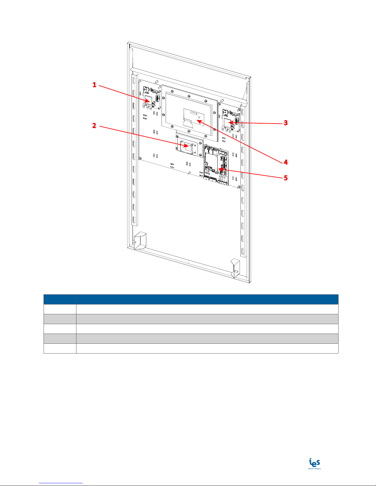
Internal door view
1
23
4
5
Position Description
1 Optionnal modem board
2 RFID reader board
3 Modem board
4 Display board
5 OCPP board
Note: May change depending on version or technical modification

www.ies-synergy.com
Installation Manual DIM016055-EN
10
Internal view - upper level
1
2
3
4
5
6
7
8
9
10
11
12
13
Position Description
1 Antennas
2 External fans for heat exchanger
3 Hood stand
4 Key locker
5 Input plate + cable gland
6 Emergency stop button
7 Heat exchanger
8 Extractor fan
9 Power module lid
10 CCU board
11 Distribution board
12 Output plate + cable gland
13 Key locker
Note: May change depending on version or technical modification

www.ies-synergy.com
Installation Manual DIM016055-EN
11
Internal view - lower level
1
2
3
5
6
7
8
9
10
11
12
13
14
15
4
Position Description
1 Antennas
2 External fans for heat exchanger
3 Hood stand
4 AC input configuration board
5 Key locker
6 Input plate + cable gland
7 Emergency stop button
8 Heat exchanger
9 Extractor fan
10 8kW Module - slave 1
11 8kW Module - slave 0
12 8kW Module - master
13 Distribution board
14 Output plate + cable gland
15 Key locker
Note: May change depending on version or technical modification
www.ies-synergy.com
Installation Manual DIM016055-EN
12
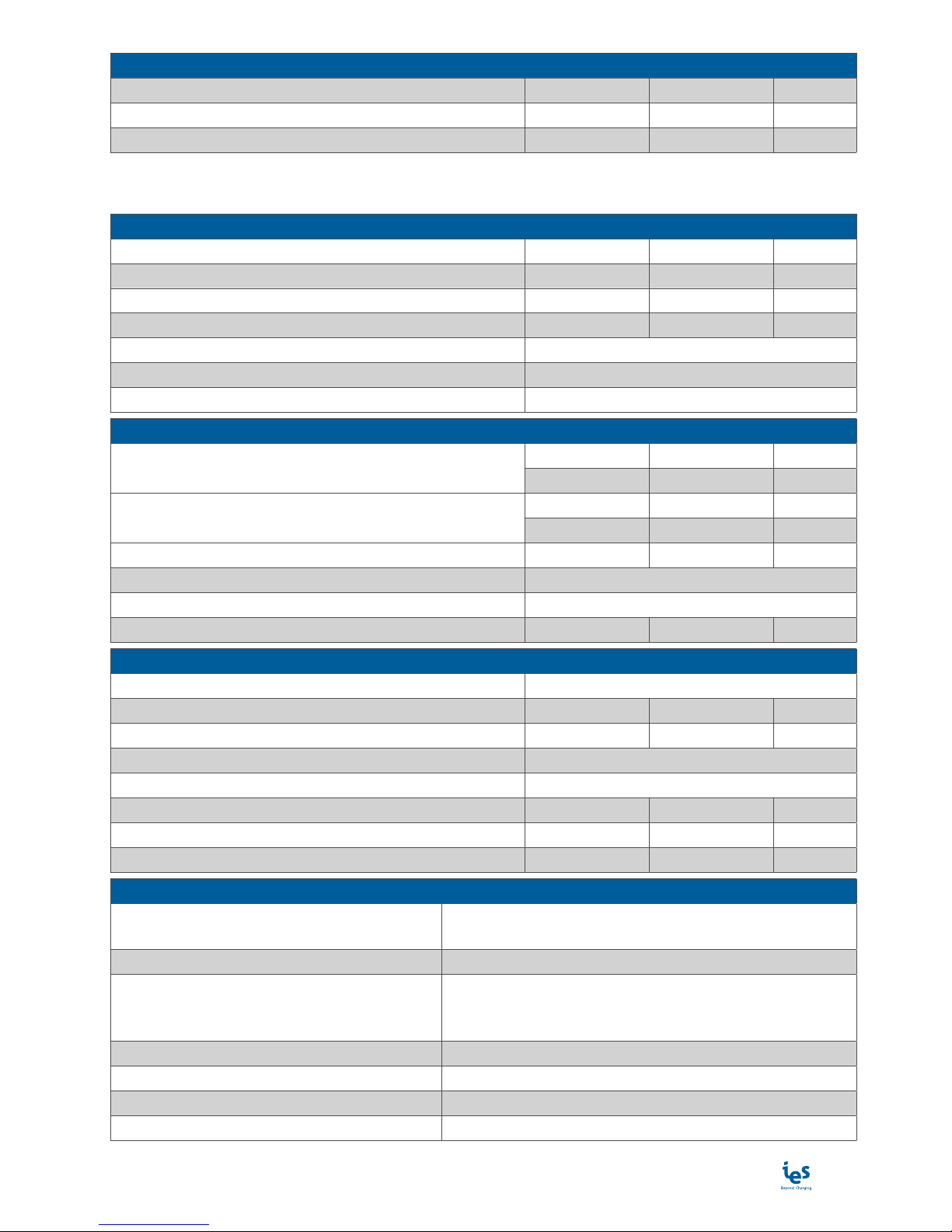
5. Specification
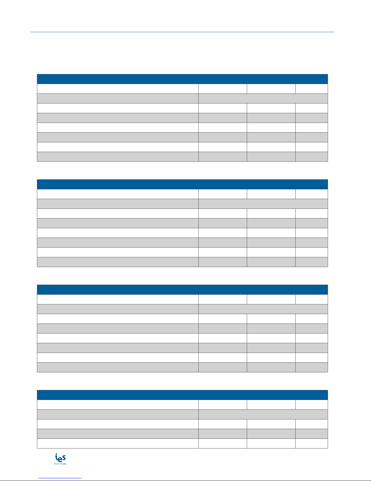
Main supply
The charging station can be connected to several mains supplies as detailed on following tables.
3-phase P1/P2/P3 + N + GND 3x380-480VAC
Mains supplies 3-phase P1/P2/P3 + N + GND 3x380-480VAC (24kW)
Mains 3-phase voltage range VAC 380-480 VAC ± 10%
Earthed electrical system TT or TN
Frequency range f 50/60 Hz ± 10%
Nominal input current IAC 40-32A Nom
Maximum input current IAC 45A Max
Power Factor PF 0,99 Nom
Efficiency ɳ95 % Nom
Harmonic current @ nominal network voltage THDi < 13 % Max
3- phase P1/P2/P3 + GND 3x208-240VAC
Mains supplies 3- phase P1/P2/P3+GND 3x208-240VAC (24kW)
Mains 3-phase voltage range VAC 208-240 VAC ± 10%
Earthed electrical system TT, TN or IT
Frequency range f 50/60 Hz ± 10%
Nominal Input current IAC 72-63A Nom
Maximum Input current IAC 80A Max
Power Factor PF 0,99 Nom
Efficiency ɳ95 % Nom
Harmonic current @ nominal network voltage THDi < 13 % Max
Single-phase P + N + GND 1x220-240VAC
Mains supply single-phase P + N + GND 1x220-240VAC (24kW)
Mains single-phase voltage range VAC 220-240 VAC ± 10%
Earthed electrical system TT or TN
Frequency range f 50/60 Hz ± 10%
Nominal Input current IAC 123-112A Nom
Maximum Input current IAC 140A Max
Power Factor PF 0,99 Nom
Efficiency ɳ95 % Nom
Harmonic current @ nominal network voltage THDi < 13 % Max
3-phase P1/P2/P3 + N + GND 3x380-400VAC with power metering(1)
Mains supplies 3-phase P1/P2/P3 + N + GND 3x380-400VAC (24kW) with power metering(1)
Mains 3-phase voltage range VAC 380-400 VAC ± 10%
Earthed electrical system TT or TN
Frequency range f 50/60 Hz ± 10%
Nominal input current IAC 40-32A Nom
Maximum input current IAC 45A Max
www.ies-synergy.com
Installation Manual DIM016055-EN
13
Mains supplies 3-phase P1/P2/P3 + N + GND 3x380-400VAC (24kW) with power metering(1)
Power Factor PF 0,99 Nom
Efficiency ɳ95 % Nom
Harmonic current @ nominal network voltage THDi < 13 % Max
Technical specification
Internal AC input protection
Inrush current limitation per phase IINRUSH LIMIT < 3 x IAC Max
Rated Current Fuse (per module) IBREAK Rating 80A typ
Breaking capacity of fuses IBREAK Capacity 80 000A Max
Max earth leakage current ILEAKAGE < 3,5 mA Max
Emergency button connection Yes
Overvoltage (IEC60664-1) OV III
Insulation protection Class (IEC60664-1) Class I
Internal DC Output
Output voltage VDC_max 530 VDC Max
VDC_min 150 VDC Min
Output current IDC_max 65A (2)(3) Max
IDC_min 1,5A Min
Max Output Power POUT 24kW Max
Output connector (charging station side) Permanent mounting
Car Plug coupler COMBO 2 or CHAdeMO
Output cable length - 4 Meters
Internal DC output protection
Hardware and software short circuit protection Yes
Software and Hardware over voltage protection adjustable +10% max
Over temperature protection - 70 °C
Reverse polarity protection Yes
DC output Contactor Yes (2 poles)
Rated Current Fuse (output) IFUSE 125 A
Galvanic isolation Vinput / output 5200 VDC
Max time for DC line discharge < 60V T<60V 1 s
Embedded Insulation device
Response time (tan) < 3sec. for asymmetrical fault
< 62sec. for symmetrical fault
Self test time At power on and every 60s during charge
Internal resistance Ri of the measuring circuit
1.5Mohms permanent
750Kohms continuous measurement
300Kohms during simultaneous switching measurement
Measurement method Continuous and switching measurement resistor method
Measuring current Im < 1,4mA at RF=0
Measurement range (Ran) 20Kohms…300Kohms
Relative uncertainty ±15%
www.ies-synergy.com
Installation Manual DIM016055-EN
14
Embedded Insulation device
Line L+/L- Voltage (Un) DC 150V…530V
System leakage capacity Ce ≤ 1µF : response value (Ran) and time (tan) are not guar-
anteed for capacity above 1µF
Parallelization
IWarning: Do not connect the insulation monitor de-
vice (IMD) in parallel !!
Response value (Ran) and time (tan) are not guaranteed.
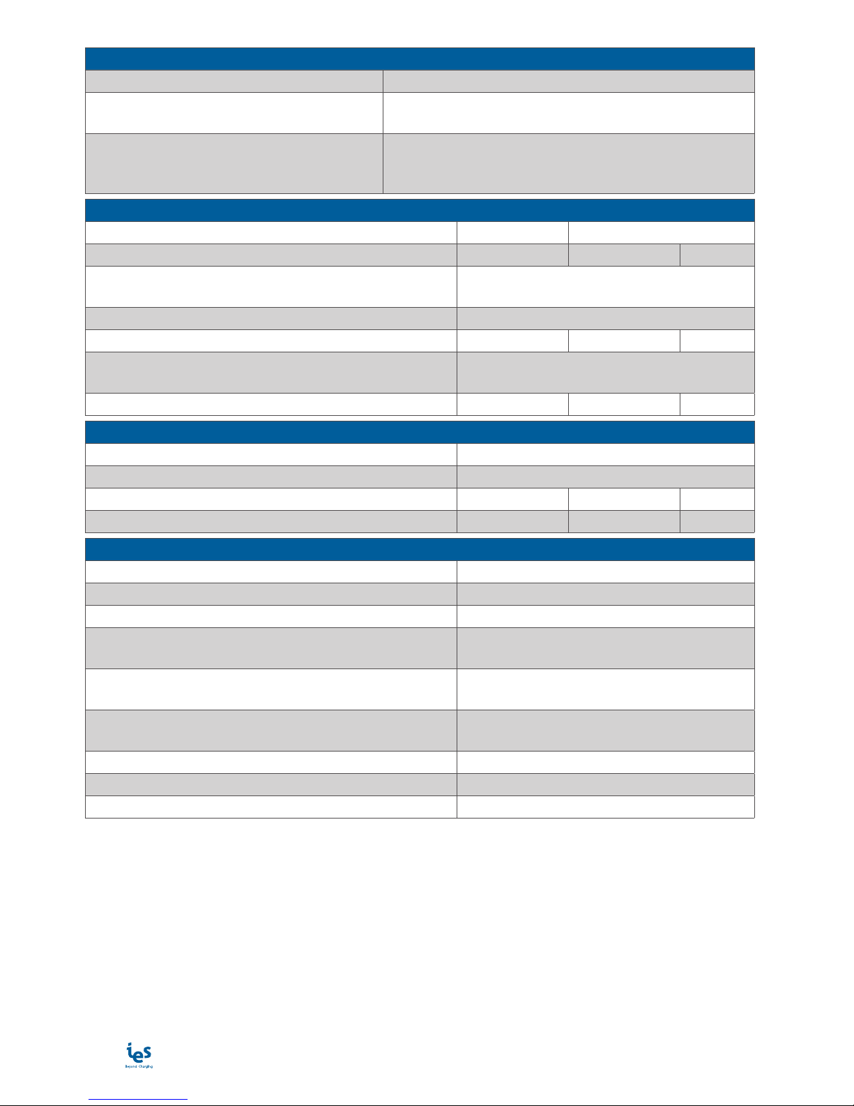
General & dimensions
External dimensions (mm) H x W x D 860 x 507 x 250 mm
Weight (without cable, or bracket) kg 66kg Max
Type of installation Mounting on a wall or on a pedestal with
proper fixation point
Fixation points 8 screws for wall mounting
Protection type (EN60529) IP IP54
Cooling systems Heatsink with forced air flow by fans IP55
without air filter
Noise (1m, all direction) Db(A) 65dbA (1m)
Climatic & Environment constraints
Operating temperature (with derating) -25°C to +55°C(4)
Storage temperature -25°C to +60°C
Relative humidity RH 10% to 95%
Installation altitude Alt 2 000m Max
Norms & standards
EC Low voltage EC directive (LVD) 2014/35/EU
EC Electromagnetic Directive (EMC) 2014/30/EU
Radio Equipment Directive (RED) 2014/53/EU
Electric vehicle conductive charging system part 1
General requirement IEC 61851-1
Electric vehicle conductive charging system part 23
DC Electric vehicle charging station IEC 61851-23
EMC requirement for OFF board electric vehicle charging
system IEC 61851-21-2
Insulation Monitor Device (IMD) IEC 61557-1 & IEC 61557-8
RoHS 2015/863/EU
Declaration of conformity CE(5) Yes
(1) EC approval pending.
(2) Max output current will be adapted versus maximum carrying current of the vehicle plug.
(3) Output current can be even reduced with the power derating versus temperature.
(4) Potential derating above 35°C.
(5) CE marking affixed on the product attest the conformity of the product with applicable requirements of rele-
vent Community harmonization legislation.
www.ies-synergy.com
Installation Manual DIM016055-EN
15
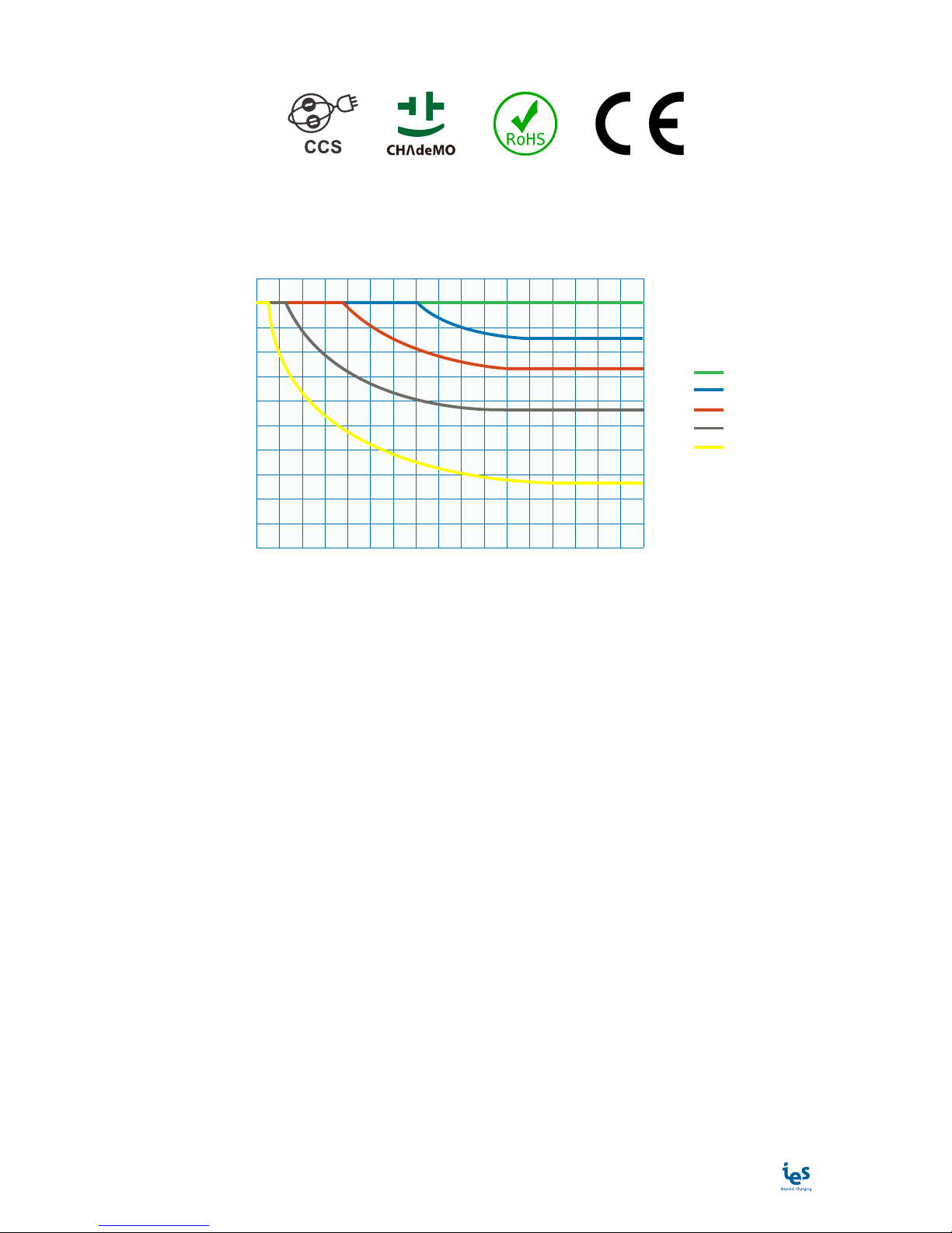
Compliance
Derating
As a direct correlation exists between the current and ambient temperature a derating curve is provided for all
charging station.
Minutes before derating
@ VOUT=370VDC & IOUT=65A
0
10
0 10 20 30 555 15 25 5035 60 7540 65 8045 70 85
20
30
40
50
60
70
90
80
100
35°C
40°C
45°C
50°C
55°C
Max Power (%)
www.ies-synergy.com
Installation Manual DIM016055-EN
16
6. Handling and storage instructions
Storage
The charging stations are supplied in individual wood crate. When commissioning the product, all the protec-
tion for transport must be removed before energization.
Keep the charging station in its original packaging in an appropriate place:
placed on dry ground or on a sheet to protect it from damp,
sheltered from dust, inclement weather and sunlight.
Storage temperature: -25°C to +60°C
Humidity: 10% to 95%
During prolonged storage, check the state of the charging station packaging regularly.
Do not store the charging station for more than a year without powering it up, to avoid the deterioration of
non-energized electronic components.
Transport
Throughout the transport phase, take all necessary measures to keep the pallet stable.
Equipment Handling
Wallbox G3 charging station is a 66kg equipment. It must be handled by two people minimum.
NOTICE
RISK OF DAMAGE TO THE CHARGING STATION
• Do not lift charger by the door. Damage will occur.
• Improper storage or handling may cause damage to the unit.
Failure to follow these instructions can result in equipment damage.
ICAUTION
RISK OF INJURY DUE TO DROPPING OR FALLING
• Follow specified procedures for hoisting operations.
• Take measures to prevent falling when you carry or transfer the unit.
Failure to follow these instructions will result in minor or moderate injury.
www.ies-synergy.com
Installation Manual DIM016055-EN
17
7. Installation
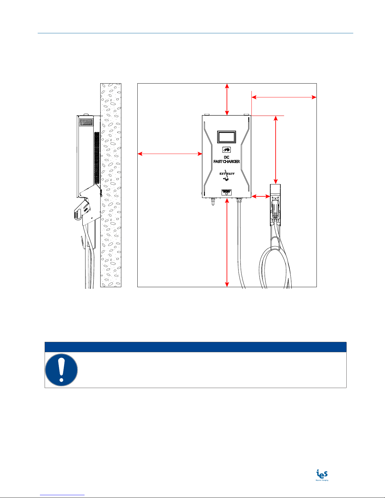
Installation rules
It is advisable to leave 100cm free space on each side and 50cm on the top and the bottom of the charging
station if it is surrounded by a wall. This free space is mandatory for charging station’s ventilation.
Never blockair flow.
1000 mm min 720 mm
min
1000 mm min
500 mm
min
700 to 1200 mm
0 mm
min
Note: All pertinent state, regional, and local safety regulations must be observed when installing and using this
device.
Note: The manufacturer cannot be held responsible for failure to follow the instructions given in this instruc-
tion sheet.
NOTICE
PREMATURE AGEING OF THE CHARGING STATION
• Do not install charging stations outside where they are exposed to direct sunlight and
inclement weather.
Failure to follow these instructions can result in accelerate power derating.

www.ies-synergy.com
Installation Manual DIM016055-EN
18
Unpacking
1. Remove four (4) phillips screws from bottom of
crate and lift crate sidewalls upwards - position 1
Unscrew lid of crate
1
1. Remove the lid of crate. You will use it to put the
charging station.
Unpacking Wallbox
2

www.ies-synergy.com
Installation Manual DIM016055-EN
19
1. Remove the screw (1) on side door - position 1
2. Remove the side panel
1
Open the side door
3
1. Remove the nuts (3) on bracket’s studs - position 1
1
Unlock Wallbox bracket
4
www.ies-synergy.com
Installation Manual DIM016055-EN
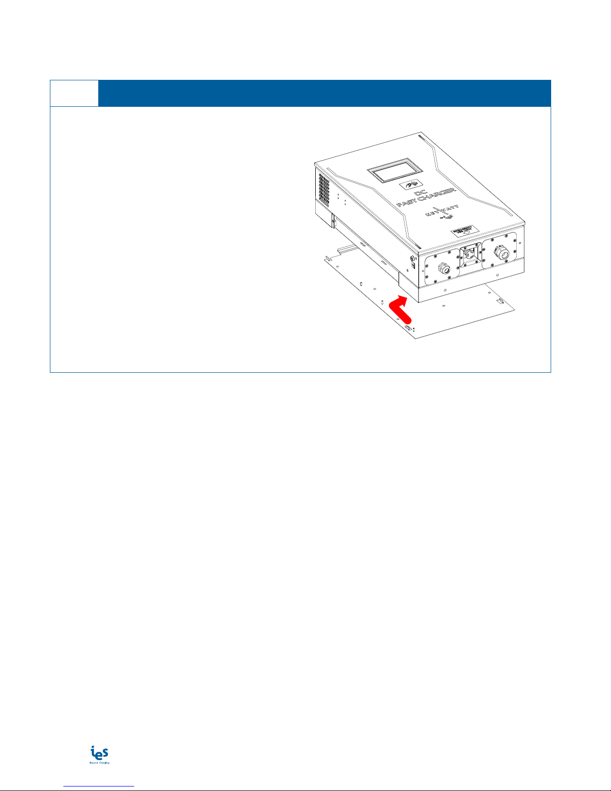
20
1. Remove the charging station from its bracket
Note: Charging station must be handled by two peo-
ple minimum.
Remove Wallbox bracket
5
Table of contents
Other IES Batteries Charger manuals


