IES Keywatt 50 Cube User manual


www.ies-synergy.com
User manual DUM1017795-EN
2
The information provided in this documentation contains general descriptions and/or technical characteristics
of the performance of the products contained herein. This documentation is not intended as a substitute for
and is not to be used for determining suitability or reliability of these products for specific user applications. It
is the duty of any such user or integrator to perform the appropriate and complete risk analysis, evaluation and
testing of the products with respect to the relevant specific application or use thereof. Neither IES Synergy nor
any of its affiliates or subsidiaries shall be responsible or liable for misuse of the information contained herein.
If you have any suggestions for improvements or amendments or have found errors in this publication, please
notify us.
You agree not to reproduce, other than for your own personal, noncommercial use, all or part of this document
on any medium whatsoever without permission of IES Synergy, given in writing. You also agree not to establish
any hypertext links to this document or its content. IES Synergy does not grant any right or license for the per-
sonal and noncommercial use of the document or its content, except for a non-exclusive license to consult it on
an “as is” basis, at your own risk. All other rights are reserved.
All pertinent state, regional, and local safety regulations must be observed when installing and using this prod-
uct. For reasons of safety and to help ensure compliance with documented system data, only the manufacturer
should perform repairs to components.
When devices are used for applications with technical safety requirements, the relevant instructions must be
followed.
Failure to use IES Synergy software or approved software with our hardware products may result in injury,
harm, or improper operating results.
Failure to observe this information can result in injury or equipment damage.
© 2019 IES Synergy. All rights reserved.

www.ies-synergy.com
User manual DUM1017795-EN
3
Table of content
1. Safety notes 4
Notice 4
Please note 4
2. About this manual 5
Purpose of this manual 5
Document scope 5
Related documents 5
User comments 5
Compliance 5
Symbol 5
Derating 6
3. General safety instructions 7
4. Overview 8
General overview 8
Dimensions 8
Control panel 9
Connection panel 10
Battery harness harting connector 10
5. Specification 12
Technical specification 12
6. Handling and storage instructions 14
Storage 14
Transport 14
7. Installation 15
Visual inspection 15
Upstream protection of charger power circuit 15
Electrical connection 15
Input harness connection 16
Battery harness installation 17
Connector and cable support installation 18
Installation of the plexiglass cover 19
8. Charger operation 20
Starting up 20
CHAdeMO mode 21
Combo mode 24
GB mode 27
List of error messages 30
9. Maintenance 32
Protection fuses location 32
10. Protecting the environment 34
Recycling Packaging 34
End-of-Life Recycling 34
www.ies-synergy.com
User manual DUM1017795-EN
4
1. Safety notes
Notice
Read these instructions carefully, and look at the equipment to become familiar with the device before trying
to install, operate, or maintain it. The following special messages may appear throughout this documentation
or on the equipment to warn of potential hazards or to call attention to information that clarifies or simplifies
a procedure.
The addition of this symbol to a Danger hazard statements indicates that an electrical hazard
exists, wich result in personal injury if the instructions are not followed.
This is the safety alert symbol. It is used to alert you to potential personnal injury hazards. Obey
all safety messages that follow this symbol to avoid possible injury or death.
IDANGER
DANGER indicates an imminently hazardous situation which, if not avoided, will result in death or seri-
ous injury.
IWARNING
WARNING indicates a potentially hazardous situation which, if not avoided, can result in death or seri-
ous injury.
ICAUTION
CAUTION indicates a potentially hazardous situation which, if not avoided, can result in minor or mod-
erate injury.
NOTICE
NOTICE is used to address practices not related to physical injury.
Please note
Electrical equipment should be installed, operated, serviced, and maintained only by qualified personnel. No
responsibility is assumed by IES Synergy for any consequences arising out of the use of this material.
A qualified person is one who has skills and knowledge related to the construction and operation of electrical
equipment and its installation, and has received safety training to recognize and avoid the hazards involved.

www.ies-synergy.com
User manual DUM1017795-EN
5
2. About this manual
Purpose of this manual
Technical documentation is an integral part of a product. Until it is disposed of, always keep the technical docu-
mentation close to the unit at hand, as it contains important information. Provide technical documentation to
the person concerned if you sell, assign or lend the product.
This guide aims to provide informations needed for installation, use and end-of life of the Keywatt 50 Cube. This
guide must be read with other related documents. This guide is intended for users of the charger.
Document scope
This guide concerns the following charger:
• P/N : PFCU1017795
Related documents
Document title Reference
User Manual DUM1017795-EN
User comments
We invite you to write to us to communicate any inaccuracies or omissions, or to make general comments or
suggestions regarding the quality of this manual.
Compliance
Symbol
The presence of this symbol on a label indicates that the charger is designed for indoor use only.

www.ies-synergy.com
User manual DUM1017795-EN
7
3. General safety instructions
IWARNING
SAVE THIS MANUAL
• To ensure proper and safe operation, please read these user instructions carefully and
keep them for future reference.
• This manual contains important instructions for the DC quick charger that shall be
followed during installation, operation and maintenance of the unit.
• This equipment shall be installed, adjusted, and serviced by qualified electrical personnel
familiar with the construction and operation of this type of equipment and associated
hazards.
Failure to follow these instructions may result in death, serious injury or equipment
damage.
IWARNING
RISK OF ELECTRIC SHOCK, INJURY, AND/OR BURNING
• Only qualified, trained and authorized people will repair, replace or adjust this equipment.
• Do not use the charger as a storage area.
• Do not let a child play near the product.
• This charger may only be used on a non-flammable surface such as concrete or similar.
• The use of the device must be restricted to indoor use.
• Keep the charger away from water or water vapor.
• Be sure to mechanically lock the connectors before connecting the charger to the mains.
• The vehicle cable must be disconnected from the vehicle before any intervention on the
charger.
• Do not attempt to open the unit or remove any of its components (covers, shutters,
doors, etc.) except by qualified personnel.
• Do not open the door at any time while input power is present.
• Wait 15 minutes before opening the door. Residual voltage remains present after the
power failure.
• Do not use this product if the cables (input or output) are frayed, have damaged insulation
or any other signs of damage.
• Do not use this product if the enclosure or the EV connectors are broken, cracked, opened
or show any other indication of damage.
• Replace the damaged cables by same caracteristics cables.
• Do not use a cord extension set, second cable assembly or adaptors in addition to the
cable assembly for the connection of the EV to the EVSE.
• Do not obstruct the ventilation openings on the front and back of the charger.
• Leave a minimum space of 300mm around the charger.
Failure to follow these instructions can result in death or serious injury
IWARNING
CAUTION: This equipment is not intended for use in residential environments and may not
provide adequate protection to radio reception in such environments.
www.ies-synergy.com
User manual DUM1017795-EN
8
4. Overview
General overview
The charger IES Cube 50kW is a mobile charging solution for the electric vehicles.
Easy to move and connect, IES mobile charging solutions facilitate fast charging in changing environments.
Thanks to its « Harting » connector, its protocol cable can be changed in a few minutes, in Combo, CHAdeMO
or GB.
Based on many years of experience, IES mobile chargers provide a robust solution to facilitate the development
of new vehicles by manufacturers.
Solid and reliable, they are also used to charge the batteries of new vehicles at the end of the production line.
Easily connectable to the mains without resorting to a heavy installation, they are also useful in concession or
repair shops.
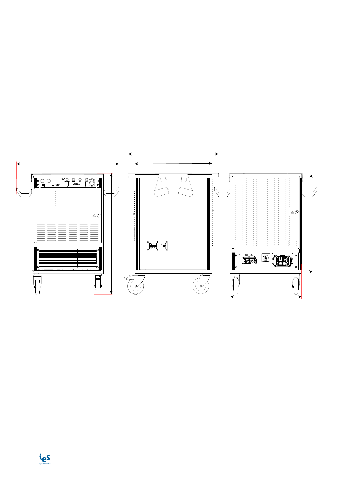
Dimensions
730
702
600
927
768
552

www.ies-synergy.com
User manual DUM1017795-EN
9
Control panel
DC CHARGER 50KW
IES-SYNERGY
❶ ❷ ❸ ❹ ❺ ❻ ❼ ❽
⓬ ⓫ ❿ ❾
Position Description
1 “START” button to launch a charge
2 “STOP” button to stop the charge
3 Voltage presence indicator light
4 “Charger ready”
5 “Failure” indicator light
6 “Auxiliary function” indicator light
7 “Charge” indicator light
8 Emergency stop button
9 Control display
10 CAN bus connection on SUB-D9 port
11 USB port
12 Ethernet network connection
Note: May change depending on version or technical modification

www.ies-synergy.com
User manual DUM1017795-EN
10
Connection panel
⓮⓯
⓭
Position Description
13 3P + GND mains input Harting connector
14 Charger disconnection device
15 Battery harness Harting connector
Note: May change depending on version or technical modification
Battery harness harting connector
⓰ ⓲ ⓳⓱
Position Description
16 GND module
17 + BAT module
18 - BAT module
19 Signal 20 pins module
Note: May change depending on version or technical modification

www.ies-synergy.com
User manual DUM1017795-EN
11
Pin assignment
Signal Name Pinout Description
GND 5 Ground
TEMP 15 Temperature signal
RC 8 Cable resistance
GND 11 Ground
LOCK 3 Connector locking signal
PROXY 4 Connector connection check
GND 16 Ground
CP 9 “Control Pilot”
GND 13 Ground
S&S1 7 Start & Stop charge 1
S&S2 1 Start & Stop charge 2
+12V 2 +12V
P&P 10 Charge permission & prohibition
GND 14 Ground
CAN L 6 CAN_H
CAN H 12 CAN_L
- 17 Internal use
- 18 Internal use
- 19 Not used
- 20 Not used

www.ies-synergy.com
User manual DUM1017795-EN
12
5. Specification
Technical specification
Mains supplies 3-phase L1/L2/L3 + GND 3x400VAC (50kW)
Mains 3-phase voltage range VAC (P-P) 400 VAC ± 10%
Earthed electrical system TT or TN
Assigned frequency f 50/60 Hz ± 10%
Maximum input current IAC 90 A Max
Nominal input current IAC 80 A Nom
Power Factor PF 0,93 Nom
Efficiency ɳ95 % Nom
Harmonic current @ nominal network voltage THDi 32 % Max
Internal AC input protection
Inrush current limitation per phase IINRUSH LIMIT < 3 x IAC Max
MCB (Main Circuit Breaker) IBREAK 100 A Nom
Breaking capacity of breaker IBREAK 6 kA Max
Max earth leakage current ILEAKAGE < 3,5 mA Max
Overvoltage (IEC60664-1) OVC III
Insulation protection Class Class II
DC output
Output voltage VDC 500 (4) Max
VDC 200 Min
Output current IDC 125 A (1)(2) Max
IDC 5 A Min
Max Output Power POUT 50kW Max
Output connector Swapped vehicle cable
Car Plug coupler COMBO1 / COMBO2 / CHAdeMO / GB
Output cable length 6 m
Internal DC output protection
Hardware and software short circuit protection Yes
Over voltage protection VDC 550 Nom
Overheating internal protection - 70 °C
DC output contactor Oui (2 pôles)
Rated Current Fuse (output) IFUSE 200 A
Galvanic isolation Vinput / output 4000 VDC
Max time for DC line discharge < 60V T<60V 1 s
Embedded Insulation device
Response time (tan) < 3sec. for asymmetrical fault
< 62sec. for symmetrical fault
Self test time At power on and every 60s during charge.
Measurement method
Non-symmetrical fault detection done continuously
Symmetrical fault detection every minute
Isolation controller integrity check before each charge
www.ies-synergy.com
User manual DUM1017795-EN
13
Embedded Insulation device
Fault trigger threshold (CCS, CHAdeMO and
GB before charging only) 100 Ω/V ± 10%
Warning detection threshold (CCS only) 500 Ω/V ± 10%
Line voltage L+/L- (Un) DC 200V…500V
System leakage capacitance Ce ≤ 1μF: response value (Ran) and time (tan) are not guar-
anteed for capacitance over 1μF.
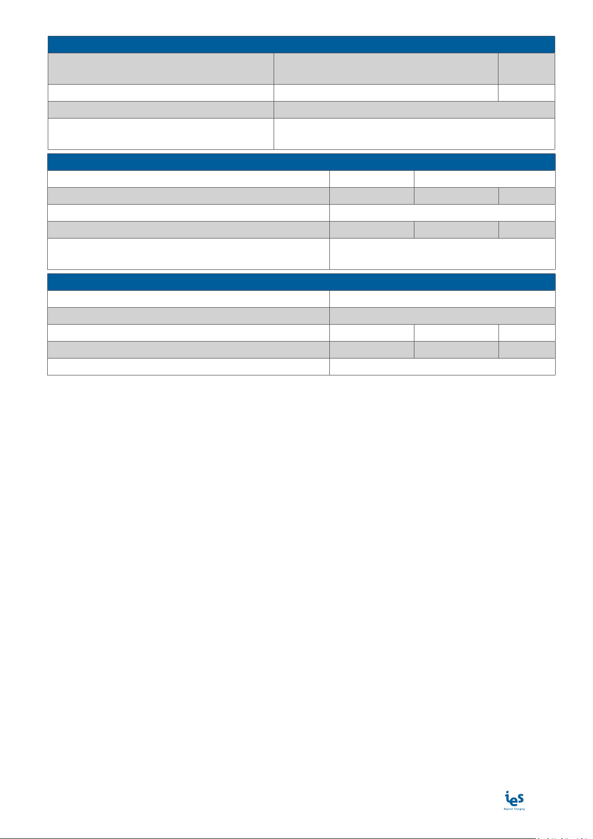
General & dimensions
External dimensions (mm) H x L x D 927 x 730 x 702 mm
Weight (without cable) kg 150kg Max
Type of installation Trolley (4 wheels)
Protection type (EN60529) IP IP21
Cooling systems Heatsink with forced air flow by fans IP54
without air filter
Climatic & Environment constraints
Operating temperature (with derating) -20°C to +40°C(3)
Storage temperature -40°C to +70°C
Relative humidity (without condensation) RH 10% to 95%
Installation altitude Alt 2 000m Max
Pollution category 2
(1) Max output current will be adapted versus maximum carrying current of the vehicle plug.
(2) Output current can be even reduced with the power derating versus temperature.
(3) Potential derating above 30°C.
(4) Refer to the current derating curve according to the mains voltage.
www.ies-synergy.com
User manual DUM1017795-EN
14
6. Handling and storage instructions
Storage
The charger is supplied in an individual wooden crate. When commissioning the product, all the protection for
transport must be removed before powering up the charger.
Keep the charger in its original packaging in an appropriate place:
• placed on dry ground or on a sheet to protect it from damp,
• sheltered from dust, inclement weather and sunlight.
Storage temperature: -40°C to +70°C
Humidity: 10 % to 95 % without condensation
During prolonged storage, check the state of the charging station packaging regularly.
Do not store the charging station for more than a year without powering it up, to avoid the deterioration of
in-active electronic components.
Transport
During the entire transport phase, take all necessary measures to maintain the stability of the transport crate.
NOTICE
RISK OF DAMAGE TO THE CHARGING STATION
Improper storage or handling may cause damage to the unit.
Failure to follow these instructions can result in equipment damage.
ICAUTION
RISK OF INJURY DUE TO DROPPING OR FALLING
• Follow specified procedures for hoisting operations.
• Take measures to prevent falling when you carry or transfer the unit.
Failure to follow these instructions can result in minor or moderate injury.
www.ies-synergy.com
User manual DUM1017795-EN
15
7. Installation
Visual inspection
Before switching on the power, check that the charging station has not suffered any damage during transport.
If there is any sign of damage, do not connect the charging station to the input power supply.
To do so would lead to a risk of electric shock and injury.
Upstream protection of charger power circuit
It is imperative to have protection of the upstream power circuit by the following electrical equipment:
• a 100A C-curve MCB,
• an RCD.
The customer is responsible for the design of the electrical installation and the choice of protection devices.
The customer must ensure the coordination of the protective devices with the charger.
All external circuits connected to your product must be of the Very Low Voltage (SELV) type and be Limited Pow-
er Sources less than 15VA and meeting the requirements of Chapters 2.2 and 2.5 of the standards IEC60950-1:
2005 + / A1: 2010 + / A2: 2013 and EN60950-1: 2006 + / A11: 2009 + / A1: 2010 + / A12: 2011 + / A2: 2013.
Electrical connection
The charger is equipped with a power cable ref. FLPLA018196 or FLPLA018900 which connects to the rear pan-
el.
IWARNING
RISK OF ELECTRIC SHOCK, INJURY, AND/OR BURNING
• Incorrect connection of the grounding conductor can result in a risk of electric shock.
• This equipment shall be installed, adjusted, and serviced by qualified electrical personnel
familiar with the construction and operation of this type of equipment and associated
hazards.
Failure to follow these instructions can result in death or serious injury

www.ies-synergy.com
User manual DUM1017795-EN
16
Input harness connection
1. Loosen the Harting connector locking tab nuts (x2)
- position ❶
2. Remove the locking tab - position ❷
3. Push on the Harting connector locking lever - po-
sition ❸
4. Connect the input harness
5. Pull the connector locking lever
6. Mechanically lock the input Harting connector
by placing back the locking tab under the Harting
connector locking lever
7. Tighten the locking tab nuts (x2)
IWARNING
Be sure to mechanically lock the connectors before
connecting the charger to the mains or to the EV.
❶
❷
❸
Input harness connection
1
Note: Visual inspection of the circuit breaker status is
possible through the transparent cover of the circuit
breaker hatch.
If the circuit breaker is in the down position (disabled)
you must reset it by following the steps below:
1. Remove the screws (x6) from the circuit breaker
hatch on the right side of the charger - position ❶
2. Remove the circuit breaker hatch cover - position
❷
3. Reset the charger internal input circuit breaker
(upper position) - position ❸
4. Close the circuit breaker hatch
5. Fix the circuit breaker hatch cover using the screws
(x6)
GRecommended torque: 2 N.m
❶
❷
❸❶
Reset the circuit breaker
2

www.ies-synergy.com
User manual DUM1017795-EN
17
Battery harness installation
IWARNING
RISK OF ELECTRIC SHOCK, INJURY, AND/OR BURNING
• Do not use a cord extension set or second cable assembly or adaptator in addition to the
coupler/cable assembly for the connection into the vehicle.
• Be sure to mechanically lock the connectors before connecting the charger to the mains.
Failure to follow these instructions can result in death or serious injury
Ouput cables and connectors are described below:
IES ref. Description Length Manufacturer Connector
FLPLA018118 COMBO 1 CABLE 6m IES
FLPLA018074 COMBO 2 CABLE 6m IES
FLPLA018116 CHADEMO CABLE 6m IES
The connection of the charging cable to the charger must be done at a standstill. This cable must not be con-
nected to the vehicle side.
1. Check that the disconnecting device is in the “OFF” position - position ❶
0 OFF
I ON
❶
www.ies-synergy.com
User manual DUM1017795-EN
18
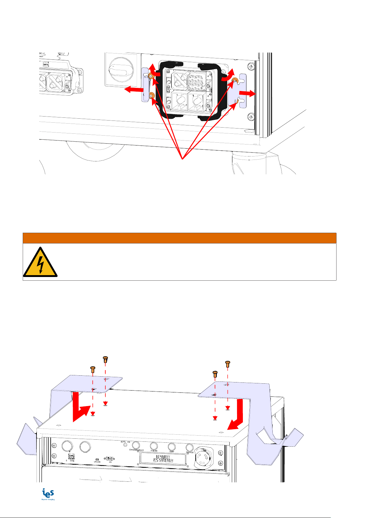
2. Loosen the nuts (x4) of the locking tabs (x2) of the Harting connector - position ❶
3. Remove the locking tabs - position ❷
4. Push on the Harting connector locking levers - position ❸
❶
❷❷
❸
❸
5. Insert the connector socket of the dedicated connection charging cable
6. Pull the connector locking levers
7. Mechanically lock the battery Harting connector by placing back the locking tabs under the Harting connec-
tor locking levers
8. Tighten the locking tabs nuts (x4)
IWARNING
RISK OF ELECTRIC SHOCK, INJURY, AND/OR BURNING
Be sure to mechanically lock the connectors before connecting the charger to the mains or
to the EV.
Failure to follow these instructions can result in death or serious injury
Connector and cable support installation
1. Place the supports MKBRN018011 (x2) on the top of the charger positioning them securely at the end of
the slotted holes - position ❶
2. Fix the supports using the screws FXVIS012307 (x4) - position ❷
GRecommended torque: 4 N.m
❷❷
❶❶

www.ies-synergy.com
User manual DUM1017795-EN
19
Installation of the plexiglass cover
1. Place without tightening completely the screws FXVIS012307 (x4) of the cover MKBRN018953 on the con-
nector and cable supports - position ❶
2. Place the cover - position ❷
3. Fix the cover tightening the screws.
GRecommended torque: 3 N.m
❶
❶
❷
www.ies-synergy.com
User manual DUM1017795-EN
20
8. Charger operation
Starting up
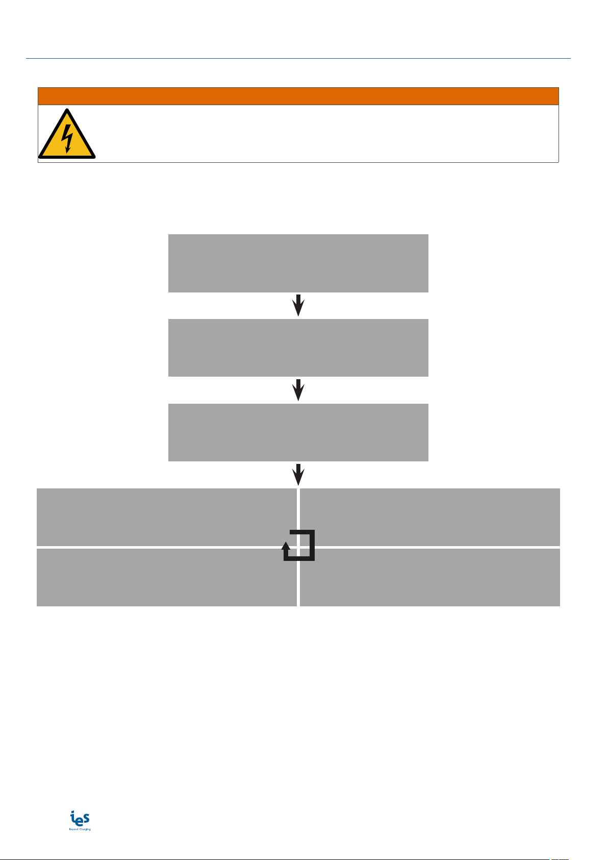
IWARNING
RISK OF ELECTRIC SHOCK, INJURY, AND/OR BURNING
Make sure no vehicle is connected before starting up the charger.
Failure to follow these instructions can result in death or serious injury
Turn the disconnecting device to the position “I ON” to power up the charger.
The charger displays its name after a startup phase represented by “...” :
...
XS50 Keywatt by IES
Universal Charger
Choose the charging mode
with the RED button
Combo 2 selected
Confirm with the GREEN button
Combo 1 selected
Confirm with the GREEN button
CHAdeMO selected
Confirm with the GREEN button
GB selected
Confirm with the GREEN button
Table of contents
Other IES Batteries Charger manuals


Popular Batteries Charger manuals by other brands

VOLTCRAFT
VOLTCRAFT B5 operating instructions

Mooreco
Mooreco iTeach owner's manual

ASSOCIATED EQUIPMENT CORPORATION
ASSOCIATED EQUIPMENT CORPORATION 6065 Operator's manual

Newer Technology
Newer Technology NuPower Charge & Sync + quick start guide

Choetech
Choetech T559-F user manual

Nokia
Nokia DT-903 user guide


