* Das Einstellen der Empfindlichkeit ist auch in gleicher Weise über die Teach-Leitung (Pin
2 / WH) möglich. Zum Aktivieren der Funktionen wird für die entsprechende Zeit die Teach-
Leitung mit L+ (Pin 1 / BN) bei PNP Geräten oder bei NPN Geräten mit L- (Pin 3 / BU) ver-
bunden. Rückmeldung: Falls das Einstellen über die Teach-Leitung nicht möglich war, wird
der Schaltausgang für 2s gesetzt. Danach geht das Gerät mit unveränderter Empfindlich-
keit in den Betriebsmodus über.
Ist die Einstellung der Empfindlichkeit nicht möglich (z. B. Hell-
signal und Dunkelsignal sind annähernd gleich stark) blinkt die
rote LED nach Schritt 3 für ca. 2s. Danach geht das Gerät mit
unveränderter Empfindlichkeit in den Betriebsmodus über.
Wird die Einstelltaste während der Programmierung 15 min.
nicht betätigt geht das Gerät automatisch mit unveränderter
Empfindlichkeit in den Betriebsmodus über.
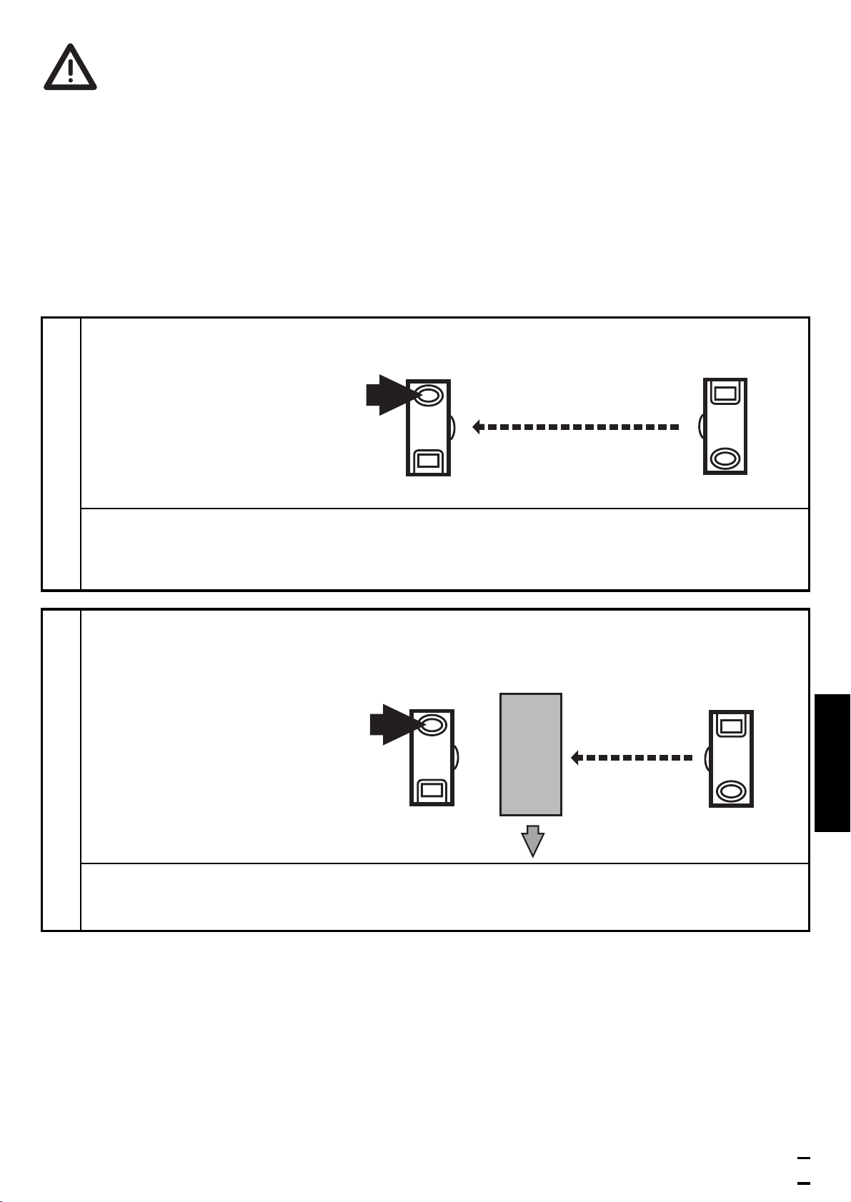
Einstellen maximaler Empfindlichkeit*
• Gehen Sie in den Programmiermodus (s. Schritt 1).
• Unterbrechen Sie den Lichtstrahl.
• Drücken Sie 2 mal die Einstelltaste (s. Schritte 2 und 3).
* Das Einstellen der maximalen Empfindlichkeit ist auch in gleicher Weise über die Teach-
Leitung (Pin 2 / WH) möglich. Zum Aktivieren der Funktionen wird für die entsprechende
Zeit die Teach-Leitung mit L+ (Pin 1 / BN) bei PNP Geräten oder bei NPN Geräten mit L-
(Pin 3 / BU) verbunden.
8
Drücken Sie 1 mal.
LEDs gelb und grün verlöschen für ca. 1s,
nach ca. 3s leuchtet die grüne LED.
Das Gerät ist im Betriebsmodus.
3
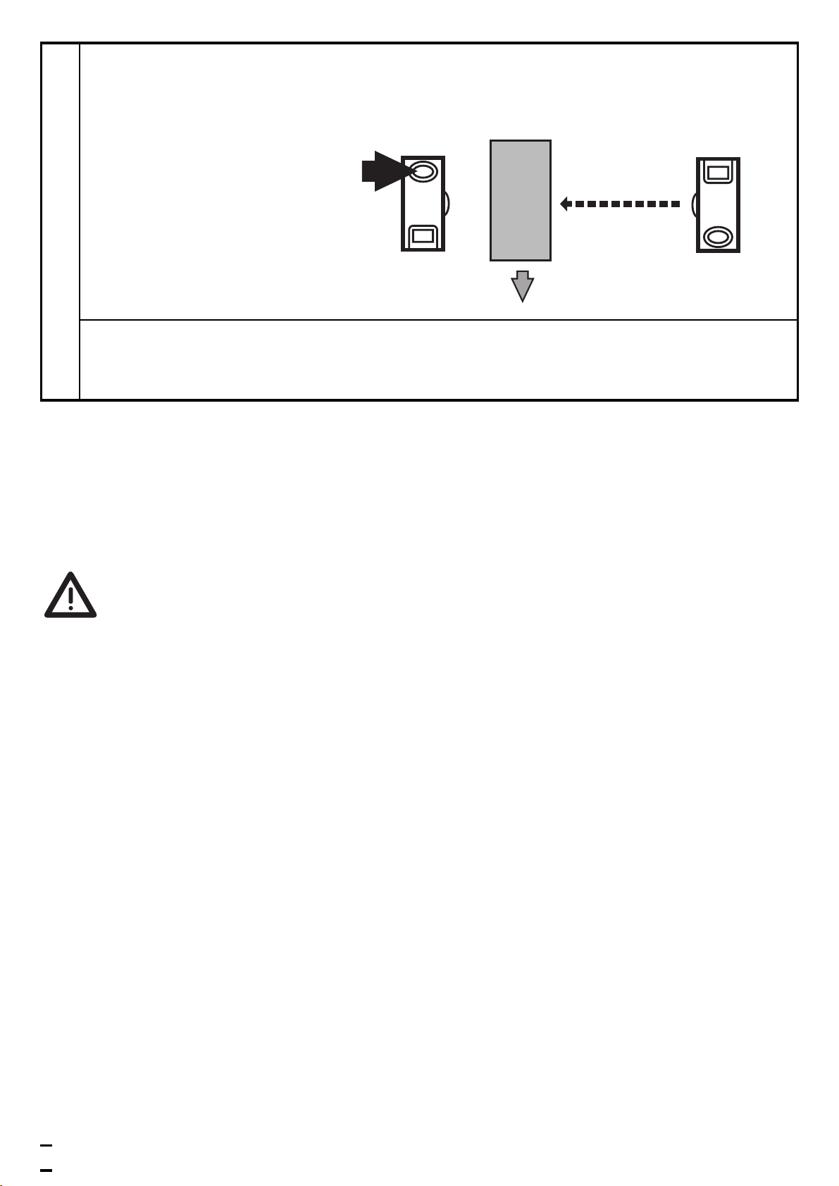
Lassen Sie während der Messung (ca. 1s) die Objekte durch den Erfas-
sungsbereich der Optik laufen (Anzahl der Objekte zwischen min. 8Hz
und max. Schaltfrequenz).