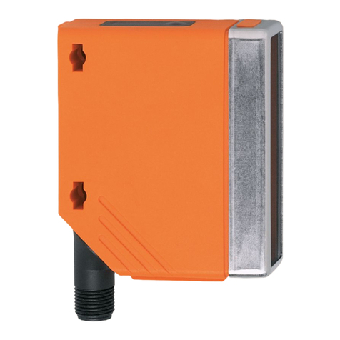
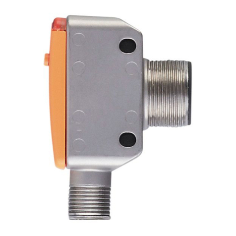
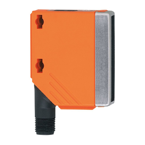
IFM Efector 200 OJ User manual

Bedienungsanleitung
Operating instructions
Notice pour utilisateurs
Reflexlichtschranke
OJ
Retro-reflective sensor
OJ
Système réflex
OJ
R
DEUTSCHENGLISHFRANÇAIS
Sachnr. 701809/02 03/2005

Bestimmungsgemäße Verwendung
In Verbindung mit Tripelspiegel oder Reflexfolie erfaßt die Reflexlicht-
schranke berührungslos transparente Gegenstände und Materialien und
meldet sie durch ein Schaltsignal.
Reichweite (r): siehe Typaufkleber (Wert bezogen auf Tripelspiegel mit
50x50 mm, E20722).
Elektrischer Anschluß
Schalten Sie die Anlage spannungsfrei. Schließen Sie das Gerät
an (s. Seite 22 oder Typenschild).
Programmieren der Ausgangsfunktion durch Einstelltaste oder
Teach Leitung (s. Seite 7).
Montage
*In den folgenden Abschnitten wird die Montage und Einstellung am Beispiel des Geräte-
Typs mit frontaler Optik gezeigt. Die Funktionen der Geräte mit seitlicher Optik sind iden-
tisch.
Befestigen Sie Tripelspiegel oder Reflexfolie. Richten Sie die Reflexlicht-
schranke darauf aus und befestigen Sie sie mit Hilfe einer Montage-
halterung (Montage siehe nächste Seite); der Lichtfleck muß den Tri-
pelspiegel treffen.
Montage der Baureihe OJ51xx
Die Geräte der Baureihe OJ51xx haben seitlich zwei Befestigungslöcher
für die Montage. Eine Montagehalterung wird nicht mitgeliefert.
Maximale Reichweite nur bei genauer Ausrichtung.
2
LED Einstelltaste LED
Einstelltaste
Seitliche Optik* Frontale Optik*

DEUTSCH
Montage der mitgelieferten Montagehalterung
Schrauben Sie die Halterung mit den beigelegten Schrauben fest und
schieben Sie das Gerät in die Führung des Halters bis die Haltefeder
einrastet.
Zum Lösen des Gerätes drücken Sie die Haltefeder mit Hilfe eines
Schraubendrehers nach unten und ziehen das Gerät von der Halte-
rung.
Wichtig! Inbetriebnahme
Die Reflexlichtschranke ist ohne weitere Einstellungen auf max. Reich-
weite eingestellt. Dies bedeutet, daß die Reflexlichtschranke zur Erfas-
sung transparenter Objekte auf jeden Fall gemäß den nachfolgend
beschriebenen Einstellungen auf optimale Betriebsreserve eingestellt
werden muß.
3

Einstellen der Empfindlichkeit bei stillstehenden Objekten*
Einstellungen 2 und 3 können auch in umgekehrter Reihenfolge erfolgen.
* Das Einstellen der Empfindlichkeit ist auch in gleicher Weise über die Teach-Leitung (Pin
2 / WH) möglich. Zum Aktivieren der Funktionen wird für die entsprechende Zeit die Teach-
Leitung mit L+ (Pin 1 / BN) bei PNP Geräten oder bei NPN Geräten mit L- (Pin 3 / BU) ver-
bunden. Rückmeldung: Falls das Einstellen über die Teach-Leitung nicht möglich war, wird
der Schaltausgang für 2s gesetzt. Danach geht das Gerät mit unveränderter Empfindlich-
keit in den Betriebsmodus über.
4
Drücken Sie ca. 2s,
bis die rote LED blinkt.
Gerät in den Programmiermodus schalten.
Die rote LED verlischt; LEDs gelb und grün blinken im Wechsel.
Das Gerät ist im Programmiermodus.
1
Empfindlichkeit mit Objekt einstellen.
Drücken Sie 1 mal.
LEDs gelb und grün verlöschen für ca. 1s,
blinken dann wieder im Wechsel.
2
Drücken Sie 1 mal.
LEDs gelb und grün verlöschen für ca. 1s,
nach ca. 3s leuchtet die grüne LED.
Das Gerät ist im Betriebsmodus.
3
Empfindlichkeit ohne Objekt einstellen.

DEUTSCH
Ist die Einstellung der Empfindlichkeit nicht möglich (z. B. Hell-
signal und Dunkelsignal sind annähernd gleich stark) blinkt die
rote LED nach Schritt 3 für ca. 2s. Danach geht das Gerät mit
unveränderter Empfindlichkeit in den Betriebsmodus über.
Wird die Einstelltaste während der Programmierung 15 min.
nicht betätigt geht das Gerät automatisch mit unveränderter
Empfindlichkeit in den Betriebsmodus über.
Einstellen der Empfindlichkeit bei bewegten Objekten*
5
Drücken Sie ca. 2s,
bis die rote LED blinkt.
Gerät in den Programmiermodus schalten.
Die rote LED verlischt; LEDs gelb und grün blinken im Wechsel.
Das Gerät ist im Programmiermodus.
1
Lassen Sie während der Messung (ca. 1s) die Objekte durch den Erfas-
sungsbereich der Optik laufen (Anzahl der Objekte zwischen min. 8Hz
und max. Schaltfrequenz).
Drücken Sie 1 mal.
LEDs gelb und grün verlöschen für ca. 1s,
blinken dann wieder im Wechsel.
2

* Das Einstellen der Empfindlichkeit ist auch in gleicher Weise über die Teach-Leitung (Pin
2 / WH) möglich. Zum Aktivieren der Funktionen wird für die entsprechende Zeit die Teach-
Leitung mit L+ (Pin 1 / BN) bei PNP Geräten oder bei NPN Geräten mit L- (Pin 3 / BU) ver-
bunden. Rückmeldung: Falls das Einstellen über die Teach-Leitung nicht möglich war, wird
der Schaltausgang für 2s gesetzt. Danach geht das Gerät mit unveränderter Empfindlich-
keit in den Betriebsmodus über.
Ist die Einstellung der Empfindlichkeit nicht möglich (z. B. Hell-
signal und Dunkelsignal sind annähernd gleich stark) blinkt die
rote LED nach Schritt 3 für ca. 2s. Danach geht das Gerät mit
unveränderter Empfindlichkeit in den Betriebsmodus über.
Wird die Einstelltaste während der Programmierung 15 min.
nicht betätigt geht das Gerät automatisch mit unveränderter
Empfindlichkeit in den Betriebsmodus über.
Zusätzlicher Einstellvorgang auf Tripelspiegel*
Sollte sich das Gerät mit den zuvor beschriebenen Einstellungen nicht
programmieren lassen, kann die Einstellung der Empfindlichkeit auf
den Tripelspiegel erfolgen. Dabei ist jedoch die Betriebsreserve auf das
zu erfassende Objekt reduziert.
• Gehen Sie in den Programmiermodus (s. Schritt 1).
• Richten Sie das Gerät so aus, daß der Tripelspiegel getroffen wird.
• Drücken Sie 2 mal die Einstelltaste (s. Schritte 2 und 3).
* Das Einstellen ist auch in gleicher Weise über die Teach-Leitung (Pin 2 / WH) möglich.
Zum Aktivieren der Funktionen wird für die entsprechende Zeit die Teach-Leitung mit L+
(Pin 1 / BN) bei PNP Geräten oder bei NPN Geräten mit L- (Pin 3 / BU) verbunden.
6
Drücken Sie 1 mal.
LEDs gelb und grün verlöschen für ca. 1s,
nach ca. 3s leuchtet die grüne LED.
Das Gerät ist im Betriebsmodus.
3
Lassen Sie während der Messung (ca. 1s) die Objekte durch den Erfas-
sungsbereich der Optik laufen (Anzahl der Objekte zwischen min. 8Hz
und max. Schaltfrequenz).

Die Einstellung der Empfindlichkeit auf den Tripelspiegel ist auf
jeden Fall möglich.
Einstellen maximaler Empfindlichkeit*
• Gehen Sie in den Programmiermodus (s. Schritt 1).
• Richten Sie das Gerät so aus, daß kein Licht reflektiert wird.
• Drücken Sie 2 mal die Einstelltaste (s. Schritte 2 und 3).
* Das Einstellen der maximalen Empfindlichkeit ist auch in gleicher Weise über die Teach-
Leitung (Pin 2 / WH) möglich. Zum Aktivieren der Funktionen wird für die entsprechende
Zeit die Teach-Leitung mit L+ (Pin 1 / BN) bei PNP Geräten oder bei NPN Geräten mit L-
(Pin 3 / BU) verbunden.
Elektronisches Schloß
Zum Verriegeln wird die Teach-Leitung für ca. 15s - 20s aktiviert*.
Zum Entriegeln wird die Teach-Leitung wieder für 15s - 20s aktiviert*.
* Zum Aktivieren der Funktionen wird für die entsprechende Zeit die Teach-Leitung (Pin 2
/ WH) mit L+ (Pin 1 / BN) bei PNP Geräten oder bei NPN Geräten mit L- (Pin 3 / BU) ver-
bunden.
Programmieren der Ausgangsfunktion*
* Das Programmieren der Ausgangsfunktion ist auch in gleicher Weise über die Teach-Lei-
tung (Pin 2 / WH) möglich. Zum Aktivieren der Funktionen wird für die entsprechende Zeit
die Teach-Leitung mit L+ (Pin 1 / BN) bei PNP Geräten oder bei NPN Geräten mit L- (Pin 3
/ BU) verbunden.
7
DEUTSCH
Drücken Sie 10s lang.
Die rote LED beginnt nach 2s
schnell zu blinken. Danach blinken
die LEDs gelb und grün im Wechsel.
Nach 10s erlöschen alle LEDs, die
Ausgangsfunktion hat von Hell-
schaltend auf Dunkelschaltend
gewechselt (oder umgekehrt).

Betrieb
Prüfen Sie, ob das Gerät sicher funktioniert. Anzeige durch LEDs.
Wartung
Halten Sie die Linsen des Geräts von Verschmutzungen frei.
8
LED grün leuchtet Gerät ist betriebsbereit.
LED gelb leuchtet Ausgang ist geschaltet.
LEDs
gelb + rot
Blinken abwechselnd, 2 Hz: Ausgang kurzgeschlossen.
Blinken abwechselnd, 1 Hz: Interne Störung.
(Ausgang ist nicht geschaltet).
LED rot leuchtet Störung bei der Objekterfassung, z. B. Dejustierung,
Verschmutzung der Linsen

Function and features
In conjunction with a prismatic reflector or reflective tape the retro-
reflective sensor detects transparent objects and materials without
contact and indicates their presence by a switched signal.
Range (r): see type label (value referred to prismatic reflector with
50x50 mm, E20722).
Electrical connection
Isolate power, then connect the unit (see page 22 or type label).
Programming of the output function by push button or programming
wire (see page 14).
Installation
* In the following sections installation and set-up are described using the example of the
type with front lens. The functions of the units with side lens are identical.
Fix prismatic reflector / reflective tape in desired position. Align the
photocell photocell towards the reflector and fasten it with a moun-
ting fixture (see the next page for installation); the light spot must hit
the prismatic reflector.
Mounting of the series OJ51xx
The units of the OJ51xx series have two fixing holes on the side for
mounting. A mounting fixture is not supplied.
Maximum range is only possible with precise alignment.
9
LED push button LED
push button
side lens* front lens*
ENGLISH

Installation of the supplied mounting fixture
Secure the mounting fixture with the screws supplied, then slide the
unit into the slot of the fixture until the spring clicks home.
To remove the unit press the spring down with a screwdriver and slide
the unit out.
NB: Commissioning
Without any further settings the retro-reflective sensor is set to the
max. range. This means that for the detection of transparent objects
the retro-reflective sensor must be set to the optimum excess gain
according to the settings described below.
10

Setting of the sensitivity with stationary objects*
You can also proceed in reverse order: first setting without the object, then with
the object.
* The sensitivity can also be set in exactly the same way using the programming wire (pin
2 / WH). To activate the functions the programming wire is connected for the appropriate
time to L+ (pin 1 / BN) for PNP units or to L- (pin 3 / BU) for NPN units. Feedback: If set-
ting was not successful via the programming wire, the output will switch for 2s. The unit
then reverts to the operating mode with the sensitivity unchanged.
11
Press for about 2s
until the red LED flashes.
Activate the programming mode of the unit.
The red LED goes out; the yellow and green LEDs flash alternately.
The unit is in the programming mode.
1
Set the sensitivity with object.
Press once.
The yellow and green LEDs go out for approx. 1s,
then flash again alternately.
2
Press once.
The yellow and green LEDs go out for approx. 1s,
after approx 3s the green LED is on.
The unit is in the operating mode.
3
Set the sensitivity without object.
ENGLISH

If the setting of the sensitivity is not possible (e.g. object signal and
background signal are about the same), the red LED flashes after
step 3 for approx. 2s. The unit then passes into the operating
mode with the sensitivity being unchanged.
If the setting button is not activated for 15 minutes during the
programming process, the unit passes automatically into the
operating mode with the sensitivity being unchanged.
Setting of the sensitivity with moving objects*
12
Press for about 2s until
the red LED flashes.
Activate the programming mode of the unit.
The red LED goes out; the yellow and green LEDs flash alternately.
The unit is in the programming mode.
1
Allow objects to pass through the detection area during the measure-
ment (about 1s) (number of the objects between min. 8Hz and max.
switching frequency).
Press once.
The yellow and green LEDs go out for approx. 1s,
then flash again alternately.
2

* The sensitivity can also be set in exactly the same way using the programming wire (pin
2 / WH). To activate the functions the programming wire is connected for the appropriate
time to L+ (pin 1 / BN) for PNP units or to L- (pin 3 / BU) for NPN units. Feedback: If set-
ting was not successful via the programming wire, the output will switch for 2s. The unit
then reverts to the operating mode with the sensitivity unchanged.
If the setting of the sensitivity is not possible (e.g. object signal
and background signal are about the same), the red LED flashes
after step 3 for approx. 2s. The unit then passes into the operat-
ing mode with the sensitivity being unchanged.
If the setting button is not activated for 15 minutes during the
programming process, the unit passes automatically into the
operating mode with the sensitivity being unchanged.
Additional setting procedure to prismatic reflector*
Should it not be possible to program the unit with the settings descri-
bed above, the sensitivity can be set to the prismatic reflector. In this
case, however, the excess gain to the object to be detected is reduced.
• Go into the programming mode (see step 1).
• Align the unit in such a way that the prismatic reflector is hit.
• Press the push button twice (see steps 2 and 3).
* The sensitivity can also be set in exactly the same way using the programming wire (pin
2 / WH). To activate the functions the programming wire is connected for the appropriate
time to L+ (pin 1 / BN) for PNP units or to L- (pin 3 / BU) for NPN units.
The setting of the sensitivity to the prismatic reflector is possible
in any case.
13
Press once.
The yellow and green LEDs go out for approx. 1s,
after approx. 3s the green LED is on.
The unit is in the operating mode.
3
Allow objects to pass through the detection area during the measure-
ment (about 1s) (number of the objects between min. 8Hz and max.
switching frequency).
ENGLISH

Setting of the maximum sensitivity*
• Go into the programming mode (step 1).
• Align the unit so that no light is reflected.
• Press the setting button twice (see steps 2 and 3).
* The maximum sensitivity can also be set in exactly the same way using the program-
ming wire (pin 2 / WH). To activate the functions the programming wire is connected for
the appropriate time to L+ (pin 1 / BN) for PNP units or to L- (pin 3 / BU) for NPN units.
Electronic lock
Activate the lock by connecting the programming wire for about 15s
– 20s*.
De-activate the lock by connecting the programming wire again for
15s – 20s*.
* To activate the functions the programming wire (pin 2 / WH) is connected to L+ (pin 1
/ BN) for PNP units or to L- (pin 3 / BU) for NPN units for the appropriate time.
Programming the output function*
* The output function can be programmed in exactly the same way using the program-
ming wire (pin 2 / WH). To activate the functions the programming wire is connected for
the appropriate time to L+ (pin 1 / BN) for PNP units or to L- (pin 3 / BU) for NPN units.
Operation
Check the safe functioning of the unit. Display by LEDs.
Maintenance
Keep the lens of the sensor free from soiling.
14
Press for 10s.
The red LED starts to flash fast after
2s. Then the yellow and green LEDs
flash alternately. After 10s all LEDs
go off, the output function has
changed from light-on mode to
dark-on mode (or vice versa).
LED green is lit Unit is ready for operation.
LED yellow is lit Output is switched.
LEDs
yellow + red
Flash alternately, 2 Hz: output short-circuited.
Flash alternately, 1 Hz: internal malfunction
(output is not switched).
LED red is lit Error in object detection, e.g. maladjustment,
soiling of the lenses.

Fonctionnement et caractéristiques
En liaison avec un réflecteur «nid d’abeille» ou une bande adhésive
réflex cette cellule réflex détecte des objets transparents et matières
sans contact et indique leur présence par un signal de commutation.
Portée (r): voir l’étiquette (valeur sur un réflecteur «nid d’abeille»
50x50 mm, E20722).
Raccordement électrique
Mettre l’installation hors tension avant le raccordement de la cel-
lule optoélectronique. Raccordement: voir page 22 ou l’étiquette
de la cellule.
Programmation de la fonction de sortie par bouton-poussoir ou par le
fil de programmation: voir page 20.
Montage
* Ci-dessous, le montage et le réglage sont décrits à l'aide d'une cellule avec détection
frontale. Les fonctions des cellules avec détection latérale sont identiques.
Fixer le réflecteur ou la bande adhésive réflex. Orienter la cellule réflex
et la fixer avec un clip de fixation (pour le montage voir la page sui-
vante); le spot lumineux doit toucher le réflecteur «nid d’abeille».
Montage de la série OJ51xx
Pour le montage, les cellules de la série OJ51xx ont deux trous de fixa-
tion latéraux. Le clip de fixation n’est pas fourni.
Portée optimale seulement avec orientation précise.
15
LED bouton-poussoir LED
bouton-poussoir
détection latérale* détection frontale*
FRANÇAIS

Montage du clip de fixation fourni
Fixer le clip avec les vis fournies et faire glisser la cellule dans le clip jus-
qu'à ce que le ressort s'enclenche.
Pour enlever la cellule pousser le ressort vers le bas avec un tournevis
et ôter la cellule du clip.
Important! Mise en service
Sans réglages supplémentaires la cellule réflex est réglée à la portée
max. Cela veut dire que pour la détection d'objets transparents la cel-
lule réflex doit être réglée à la capacité de réserve optimum selon le
réglage décrit ci-après.
16

Réglage de la sensibilité en cas d’objets statiques*
Vous pouvez également procéder dans l’ordre inverse: régler d’abord sans
objet, ensuite avec l’objet.
* Le réglage de la sensibilité peut également être effectué de la même façon par le fil de
programmation (broche 2 / WH). Pour activer les fonctions le fil de programmation est rac-
cordé à L+ (broche 1 / BN) pour les cellules PNP ou à L- (broche 3 / BU) pour les cellules
NPN pendant le temps correspondant. Rétro-information: Si le réglage par le fil de pro-
grammation n'est pas possible (par ex. le signal de l'objet et le signal de l'arrière-plan ont
presque la même intensité), la sortie de commutation est commutée pendant 2 s. Ensuite
la cellule passe au mode de fonctionnement sans changer la sensibilité.
17
Appuyer pendant env. 2s
jusqu’à ce que la LED
rouge clignote.
Activer le mode programmation de la cellule.
La LED rouge s’éteint, les LED jaune et verte clignotent alternativement.
La cellule est en mode programmation.
1
Régler la sensibilité avec l’objet.
Appuyer une fois.
Les LED jaune et verte s’éteignent pendant env. 1s,
ensuite elles clignotent de nouveau alternativement.
2
Appuyer une fois.
Les LED jaune et verte s’éteignent pendant env. 1s,
après env. 3s la LED verte s’allume.
La cellule est réglée et elle est en mode fonctionnement.
3
Régler la sensibilité sans objet.
FRANÇAIS

Si le réglage de la sensibilité n’est pas possible (p. ex. le signal de
l’objet et le signal de l’arrière-plan ont presque la même inten-
sité), la LED rouge clignote après l’étape 3 pendant env. 2s.
Ensuite la cellule passe au mode de fonctionnement sans chan-
ger la sensibilité.
Si le bouton-poussoir n'est pas appuyé pendant 15 minutes lors
de la programmation, la cellule passe automatiquement au
mode de fonctionnement sans changer la sensibilité.
Réglage de la sensibilité en cas d’objets mobiles*
18
Appuyer pendant env. 2s
jusqu’à ce que la LED
rouge clignote.
Activer le mode programmation de la cellule.
La LED rouge s’éteint, les LED jaune et verte clignotent alternativement.
La cellule est en mode programmation.
1
Laisser les objets aller à travers la zone de détection de la cellule
(nombre des objets entre min. 8Hz et fréquence de commutation
maximale) pendant la mesure (env. 1s).
Appuyer une fois.
Les LED jaune et verte s’éteignent pendant env. 1s,
ensuite elles clignotent de nouveau alternativement.
2

* Le réglage de la sensibilité peut également être effectué de la même façon par le fil de
programmation (broche 2 / WH). Pour activer les fonctions le fil de programmation est rac-
cordé à L+ (broche 1 / BN) pour les cellules PNP ou à L- (broche 3 / BU) pour les cellules
NPN pendant le temps correspondant. Rétro-information: Si le réglage par le fil de pro-
grammation n'est pas possible (par ex. le signal de l'objet et le signal de l'arrière-plan ont
presque la même intensité), la sortie de commutation est commutée pendant 2 s. Ensuite
la cellule passe au mode de fonctionnement sans changer la sensibilité.
Si le réglage de la sensibilité n’est pas possible (p. ex. le signal de
l’objet et le signal de l’arrière-plan ont presque la même inten-
sité), la LED rouge clignote après l’étape 3 pendant env. 2s.
Ensuite la cellule passe au mode de fonctionnement sans chan-
ger la sensibilité.
Si le bouton-poussoir n'est pas appuyé pendant 15 minutes lors
de la programmation, la cellule passe automatiquement au
mode de fonctionnement sans changer la sensibilité.
Procédure de réglage supplémentaire sur réflecteur
"nid d'abeille*
Si la cellule ne peut pas être programmée avec les réglages décrits ci-
dessus, le réglage de la sensibilité peut être effectué sur le réflecteur
"nid d'abeille". Dans ce cas cependant, la capacité de réserve sur l'ob-
jet à détecter est réduite.
• Passer dans le mode de programmation (voir pas 1).
• Aligner la cellule afin que le réflecteur "nid d'abeille" soit touché
par le faisceau optique.
19
Appuyer une fois.
Les LED jaune et verte s’éteignent pendant env. 1s,
après env. 3s la LED verte s’allume.
La cellule est réglée et elle est en mode fonctionnement.
3
Laisser les objets aller à travers la zone de détection de la cellule
(nombre des objets entre min. 8Hz et fréquence de commutation
maximale) pendant la mesure (env. 1s).
FRANÇAIS

• Appuyer sur le bouton-poussoir 2 fois (voir pas 2 et 3).
* Le réglage de la sensibilité maximale peut également être effectué de la même façon
par le fil de programmation (broche 2 / WH). Pour activer les fonctions le fil de program-
mation est raccordé à L+ (broche 1 / BN) pour les cellules PNP ou à L- (broche 3 / BU)
pour les cellules NPN pendant le temps correspondant.
Le réglage de la sensibilité sur le réflecteur "nid d'abeille" est
possible dans tous les cas.
Réglage de la sensibilité maximale*
• Passer au mode programmation (étape 1).
• Orienter la cellule afin que la lumière ne soit pas réfléchie.
• Appuyer sur le bouton de réglage deux fois (voir étapes 2 et 3).
* Le réglage de la sensibilité maximale peut également être effectué de la même façon
par le fil de programmation (broche 2 / WH). Pour activer les fonctions le fil de program-
mation est raccordé à L+ (broche 1 / BN) pour les cellules PNP ou à L- (broche 3 / BU)
pour les cellules NPN pendant le temps correspondant.
Verrou électronique
Pour verrouiller la cellule le fil de programmation doit être activé pen-
dant env. 15s – 20s*.
Pour déverrouiller le fil de programmation doit être activé de nouveau
pendant env. 15s – 20s*.
* Pour activer les fonctions le fil de programmation (broche 2 / WH) est raccordé à L+
(broche 1 / BN) pour les cellules PNP ou à L- (broche 3 / BU) pour les cellules NPN pendant
le temps correspondant.
Programmation de la fonction de sortie*
* La programmation de la fonction de sortie peut également être effectuée de la même
façon par le fil de programmation (broche 2 / WH). Pour activer les fonctions le fil de pro-
grammation est raccordé à L+ (broche 1 / BN) pour les cellules PNP ou à L- (broche 3 / BU)
pour les cellules NPN pendant le temps correspondant.
20
Appuyer pendant env.
10s jusqu'à ce que tou-
tes les LED s'éteignent.
La LED rouge commence à cligno-
ter rapidement après 2s. Ensuite les
LED jaune et verte clignotent alter-
nativement. Après 10s toutes les
LED s'éteignent, la sortie a changé
de NF à NO (ou vice versa).
Other manuals for Efector 200 OJ
1
Table of contents
Languages:
Other IFM Accessories manuals

IFM
IFM PM16 Series User manual

IFM
IFM SAxx04 Series User manual

IFM
IFM PN422 Series User manual

IFM
IFM Efector 200 O5 User manual

IFM
IFM Efector200 OJ51 Series User manual

IFM
IFM O5D10 Series User manual

IFM
IFM O5D15 Series User manual

IFM
IFM Efector 200 O6E3 User manual

IFM
IFM Efector600 TN2531 User manual

IFM
IFM TK61 Series User manual
Popular Accessories manuals by other brands

ABB
ABB Wireless Proximity Switches Planning and Installation Guidelines

Honeywell
Honeywell PEHA 940 RS Installation and operating instructions

Wagan
Wagan JUMPER 9796 user manual

ShadeLab
ShadeLab PIUMA installation manual

Mara
Mara SCC-84B065E user manual

Endress+Hauser
Endress+Hauser CLS15D operating instructions