7.2 Setting via IO-Link
This unit has an IO-Link communication interface which enables direct access
to process and diagnostic data� In addition it is possible to set the parameters of
the unit during operation� Operation of the unit via IO-Link interface requires an
IO-Link master�
With a PC, suitable IO-Link software and an IO-Link adapter cable communication
is possible when the system is not in operation�
The IODDs necessary for the configuration of the unit, detailed information about
process data structure, diagnostic information, parameter addresses and the
necessary information about the required IO-Link hardware and software can be
found at www�ifm�com�
7.2.1 Adjustable parameters
Among others, the following parameters can be set via IO-Link�
A table of all adjustable parameters can be found at www�ifm�com�
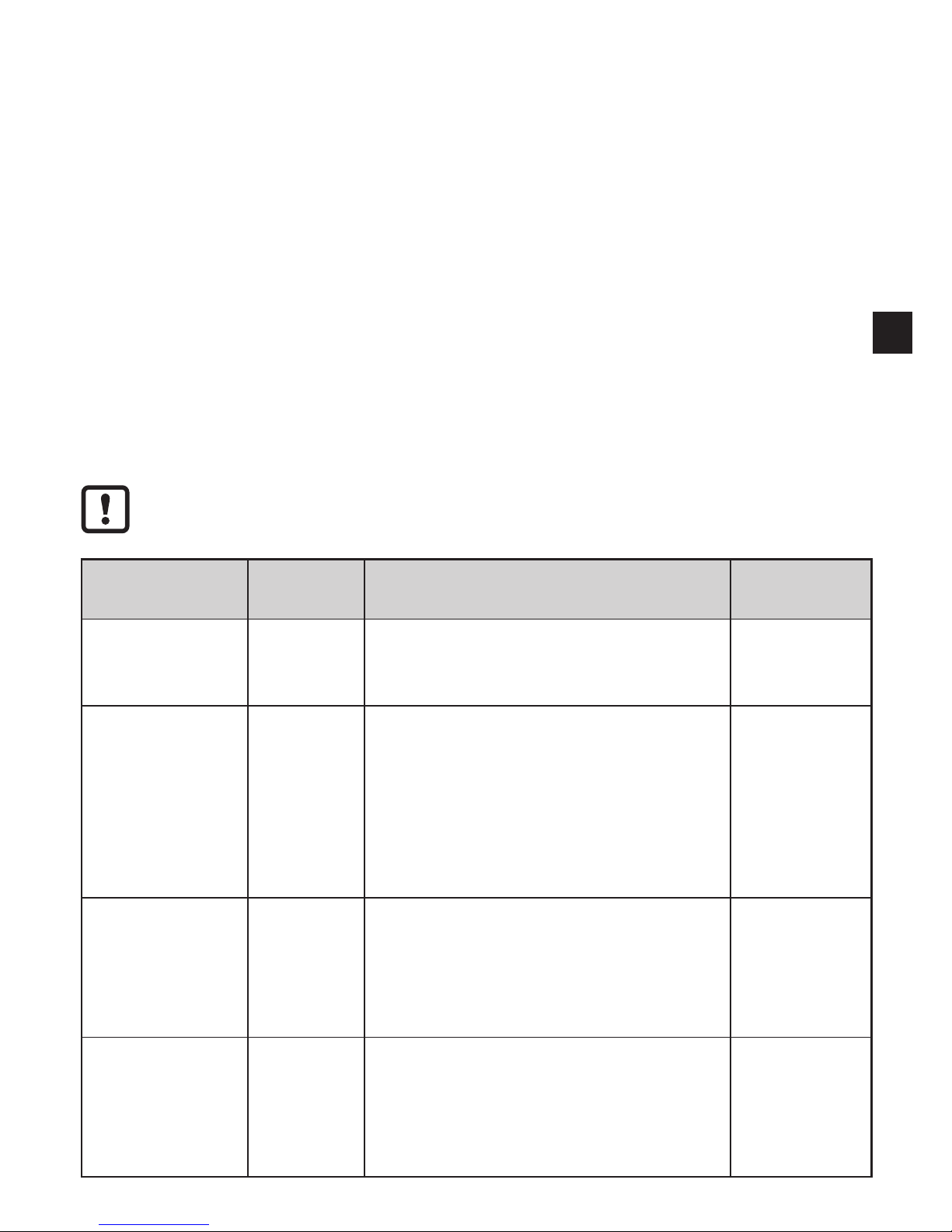
Parameter name Values Description Default
setting
SSC1 Param�
SP1
17 mm ���
100 mm
Setting of the switch point with a step in-
crement of 1 mm� After a teach the value
resulting from this teach is displayed�
Please refer to
the datasheet
value "range"
Teach SP1 TP1 Teach sequence to set switch point
SP1� Part one (TP1): teach on object�
Both parts of the teach sequence, TP1
and TP2, have to be executed, in order
to place switch point SP1 between the
object and the background
(TP = teach point)�
N� A�
Teach SP1 TP2 Teach sequence to set switch point SP1�
Part two (TP2): teach on background�
Both parts of the teach sequence, TP1
and TP2, have to be executed
(TP = teach point)�
N� A�
Teach Custom
SP1 without
target
Teach on background only, the switch
point will be defined slightly in front of
the background� Choose this setting as
an alternative to Teach SP1 if no target
is available�
N� A�