IFM DF21 Series User manual

Installation instructions
Electronic circuit breakers, IO-Link
for the 24 V DC secondary circuit
DF21xx
DF22xx
80278886 / 00 10 / 2018
UK

2
1 Preliminary note
This document applies to the DF21xx supply modules and the DF22xx circuit
protection modules.
Read this document before use to familiarise yourself with operating conditions,
installation and operation. Keep this document during the entire duration of use of
the device.
WARNING
Adhere to the warning notes and safety instructions (→ 2 Safety instructions).
The devices are not suitable for battery-backed applications.
2 Safety instructions
• The devices are intended for use with a 24 V DC safety extra-low voltage.
• A wrong connection to voltage which is higher and/or not safely isolated may
lead to damage or conditions which are dangerous to life.
• Use the supply module only with the matching circuit protection modules.
• Observe the technical data of the circuit protection modules used.
• The devices must be installed, connected and put into operation by a qualified
electrician.
• Adhere to the national regulations regarding the installation and selection of
cables.
• Do not mount the devices and do not actuate the contact levers while live.
• Supply the devices with energy only after they have been properly installed.
• After triggering a circuit protection module and before power on again, remove
the cause of triggering (short circuit or overload).
• Check the devices for damage prior to installation. Faulty devices must not be
used.
• In case of malfunction of the unit or queries, please contact the manufacturer.
Any tampering with the device can seriously affect the safety of operators and
machinery.This is not permitted and leads to the exclusion of any liability and
warranty claims.

3
UK
3 Installation
►Mount the devices on a 35 mm rail.
1
2
3
4
Example DF22xx circuit protection module
1: rail
2: contact lever
3: installation area
4: operating area
4 Electrical connection
►Dimension cables according to input and output current.
►Insert wires directly into the terminals as shown on the device label.
Art. no. Terminals Potential Cross-
section
[mm²]
Stripping
length
[mm]
DF21xx 24 V DC supply 0.5...10 18
0 V 0.14...2.5 8...10
L+, C/Q, L- IO-Link 0.25...0.5 6
DF22xx O1 or O1/O2 current outputs 0.14...2.5 8...10
To disconnect press the orange pusher using a suitable tool.
To open the push-in terminals IO-Link use a 2 mm wide micro screwdriver.

4
5 Operating and display elements
5
3
1
2
4
3
1
2
4
Example DF21 supply module
1: panel for labelling
2: status LED
3: push-in terminals IO-Link
4: push-in terminal 0 V
5: push-in terminal 24 V DC
Example DF22xx circuit protection module
1: panel for labelling
2: ON/OFF/reset button and status LED
(channel 2)
3: ON/OFF/reset button and status LED
(channel 1)
4: push-in terminals outputs 1/2
5.1 DF21xx supply modules
Status LED Operating mode IO-Link communication
—off missing operating voltage no
Green on correct operation (→ 5.1.1) yes
flashing independent operation(→ 5.1.2) no
Orange on uncritical error (→ 5.1.3) yes
flashing no
Red on critical error (→ 5.1.4) no
flashing system start (→ 5.1.5)
5.1.1 Correct operation
No fault occurred and there is connection to the IO-Link master.

5
UK
5.1.2 Independent operation
No connection to the IO-Link master. If there is no connection to the IO-Link
master when the operating voltage has been applied, the supply module transfers
the parameter data to the connected circuit protection modules. The behaviour
of the connected circuit protection modules is controlled via the configuration
of the supply module. Either the status of the circuit protection modules is kept
(FREEZE) or the circuit protection modules are switched off (UNFREEZE). If there
is again connection to the IO-Link master and no fault occurred, the device goes
to the "correct operation" mode.
5.1.3 Uncritical error
No valid configuration data is available. The connected circuit protection modules
remain switched off. Cyclic data exchange is not possible, acyclic data exchange
is conditionally possible. After the device has received the valid configuration and
parameter data, it quits this operating mode.
5.1.4 Critical error
During initialisation an error is found or a critical error occurs. Communication with
the IO-Link master is not possible. The connected circuit protection modules are
and remain switched off.
►Reboot the device.
5.1.5 System start
The supply module is initialised when the operating voltage is applied. During this
time communication with the IO-Link master is not possible.
5.2 DF22xx circuit protection modules
The different operating states of the circuit protection modules are indicated by
LEDs.
—off missing operating voltage,
error in initialisation or
channel switched off via button
off
Green on channel switched on via button or IO-
Link, no error
on
Green/
orange
flashing load current limit reached on

6
Status LED Operating status Status of load output
Orange on overload or short circuit until discon-
nection
on
Channel switched on via button and
switched off via IO-Link
off
Red on triggering via short circuit or overload off
undervoltage in ON status with auto-
matic switching on again
5.3 Interrogation of module to confirm the set nominal current
Only for circuit protection modules with adjustable nominal current.
►Press the ON/OFF/reset button of the requested channel between 2 and 5
seconds.
> The status LED of the selected channel flashes red once.
> The status LED flashes orange to display the set nominal current. The LED
Flashes red once to confirm completion of the cycle. The LED flashes orange,
once or multiple times, in accordance with nominal current setting in amperes
(orange flashing once = 1 A; orange flashing twice = 2 A; etc.).
> The set nominal current is displayed five times. After 5 cycles the display
changes to the current operating status.To interrupt/stop the interrogation cycle,
and return to normal status indication mode, press the ON/OFF/reset button of
the requested channel at any time.
5.4 Setting of the nominal current
Only for circuit protection modules with adjustable nominal current.
► Set the nominal current via IO-Link using a corresponding parameter setting
software.

7
UK
6 Technical data
Art. no.
DF210x
DF2208
DF2210
DF2212
DF2214
DF2216
DF2220
Supply module ●-
Circuit protection module -●
Interface
Number of circuit protection
modules
-≤ 8 per supply module
Electrical data
Input voltage [V]
Nominal voltage [V]
NEC Class 2 ---● ● - -
Input current
(= max. total current)
[A] 40 -
Number of channels - 1 2
Nominal current IN
fail-safe IN
[A] - 8
(8)
10
(10)
2
(2)
4
(4)
6
(6.3)
1...10
(16)
Mechanical data
Installation
Device width [mm]
Ambient temperature [°C]
Storage temperature [°C]
Protection rating
(→ 3 Installation)
Electrical connection
Type
● = applicable
Data sheets are available at: www.ifm.com
When read with a smartphone, the printed QR codes directly lead to the data
sheet and more information.

8
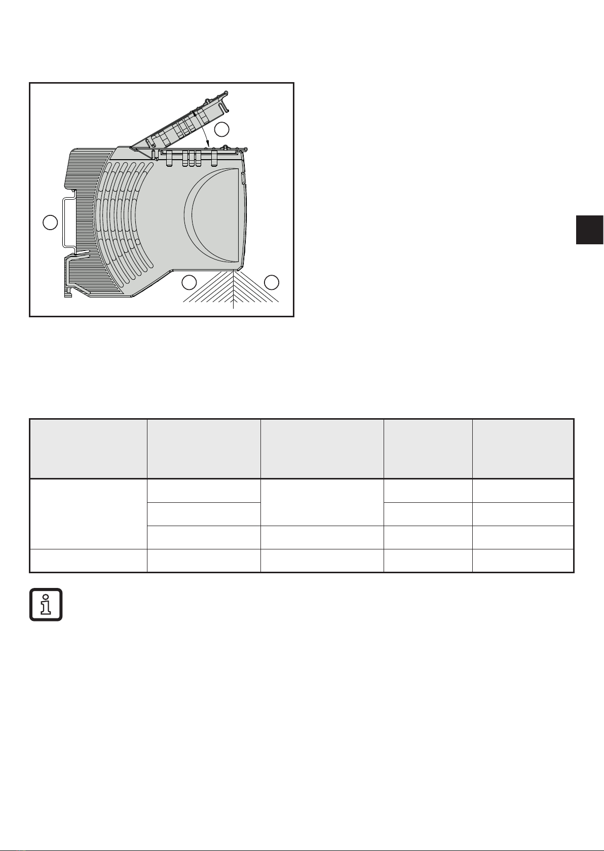
6.1 Temperature factor / continuous current rating
The time-current characteristic curve depends on the ambient temperature. To
determine the max. permitted load current multiply the nominal device current by
the temperature factor taking into consideration the series connection.
Ambient temperature [°C] 0 10 23 40 50 60
Temperature factor 1 1 1 0.95 0.90 0.85
With series installation the nominal device current can be max. 80% or has to be
overdimensioned accordingly. With increased temperature the load current war-
ning limit "warning limit typ. 0.8 x IN" is reduced by the temperature factor.
6.2 Fail-safe element
The load circuits are additionally protected by the circuit protection modules that
are equipped with a fail-safe element (integrated fuse). The fail-safe element is
adapted to the nominal current INof the respective circuit protection module and
the respective wire cross-sections.
7 IO-Link
The load current warning threshold can be configured via the IO-Link inter-
face to provide a visual warning and a warning via IO-Link with a capacity
utilisation between 50 and 100 %.
The IO-Link devices can also be used as stand-alone devices without IO-
Link master.
Extended functions of the DF2101 head module via IO-Link:
• Min. / max. value generation of the measured current and voltage values for
each channel over any period of time
• Averaging of the measured current and voltage values for each channel over
any period of time
• Permanent switching on of individual channels in order to ignore the cyclic
data exchange (e.g. to guarantee the voltage supply of important devices). The
safety function remains active.
You will find the IODDs necessary for the configuration of an IO-Link device and
detailed information about parameter setting tools, process data structure, dia-
gnostic information and parameter addresses at www.ifm.com/gb/io-link.
Other manuals for DF21 Series
1
This manual suits for next models
8
Table of contents
Other IFM Circuit Breaker manuals
Popular Circuit Breaker manuals by other brands

Siemens
Siemens SIRIUS 3RV2.4 Original operating instructions

Eaton
Eaton NZM2-XSRM-LR Instruction leaflet

ADB Safegate
ADB Safegate SCO instruction manual

Fuji Electric
Fuji Electric BW32AAG technical information

GE
GE MicroVersaTrip AKR-75 installation instructions

ABB
ABB K-Line Plus KP-32 Installation & maintenance instructions