ESAB MultiPower 460 Pulse User manual

0558004165 02 / 2007
MultiPower 460 Pulse
DC WELDING POWER SOURCE
INSTRUCTION MANUAL
This manual provides complete instructions for the following
power sources starting with Serial Number MxxJ211xxx, March 2002:
ESAB ITEM NO. 0558002877

2
These INSTRUCTIONS are for experienced operators. If you are not fully familiar with the principles
ofoperationandsafepracticesforarcweldingandcuttingequipment,weurgeyoutoreadourbooklet,
"PrecautionsandSafePracticesforArcWelding,Cutting,andGouging,"Form52-529. DoNOTpermit
untrainedpersonstoinstall,operate,ormaintain thisequipment. DoNOTattemptto installoroperate
this equipment until you have read and fully understand these instructions. If you do not fully
understandtheseinstructions,contactyoursupplierforfurtherinformation. BesuretoreadtheSafety
Precautions before installing or operating this equipment.
BESURE THISINFORMATION REACHESTHE OPERATOR.
YOU CAN GET EXTRA COPIES THROUGH YOUR SUPPLIER.
USER RESPONSIBILITY
Thisequipmentwillperforminconformitywiththedescriptionthereofcontainedinthismanualand
accompanying labels and/or inserts when installed, operated, maintained and repaired in accor-
dancewiththeinstructionsprovided. Thisequipmentmustbecheckedperiodically. Malfunctioning
orpoorlymaintainedequipmentshouldnotbeused. Partsthatarebroken,missing,worn,distorted
or contaminated should be replaced immediately. Should such repair or replacement become
necessary,themanufacturerrecommendsthatatelephoneorwrittenrequestforserviceadvicebe
madetotheAuthorizedDistributorfromwhomitwaspurchased.
This equipment or any of its parts should not be altered without the prior written approval of the
manufacturer. Theuserofthisequipmentshallhavethesoleresponsibilityforanymalfunctionwhich
resultsfromimproperuse,faultymaintenance,damage,improperrepairoralterationbyanyoneother
thanthemanufactureroraservicefacilitydesignatedbythemanufacturer.

3
TABLE OF CONTENTS
SECTION TITLE PAGE
SECTION1 SAFETY ..............................................................................................................................................5
SECTION2 DESCRIPTION .................................................................................................................................... 11
SECTION3 INSTALLATION ................................................................................................................................. 19
SECTION4 OPERATION .......................................................................................................................................25
SECTION5 MAINTENANCE.................................................................................................................................. 35
SECTION6 REPLACEMENT PARTS................................................................................................................... 43

4
TABLE OF CONTENTS

5
SECTION 1 SAFETY PRECAUTIONS
WARNING: These Safety Precautions are for
your protection. They summarize precaution-
ary information from the references listed in
Additional Safety Information section. Before
performing any installation or operating pro-
cedures, be sure to read and follow the safety precautions
listed below as well as all other manuals, material safety
data sheets, labels, etc. Failure to observe Safety Precau-
tions can result in injury or death.
PROTECT YOURSELF AND OTHERS --
Somewelding,cutting,andgougingpro-
cesses are noisy and require ear pro-
tection.Thearc,likethesun,emitsultra-
violet (UV) and other radiation and can
injureskinand eyes. Hot metal can cause burns. Train-
ingintheproperuse ofthe processesandequipment is
essential to prevent accidents. Therefore:
1. Alwayswearsafetyglasses withsideshieldsinany work
area, even if welding helmets, face shields, and goggles
are also required.
2. Use a face shield fitted with the correct filter and cover
plates to protect your eyes, face, neck, and ears from
sparks and rays of the arc when operating or observing
operations.Warnbystandersnottowatchthearcandnot
toexposethemselvestotheraysoftheelectric-arcorhot
metal.
3. Wearflameproofgauntlettypegloves,heavylong-sleeve
shirt, cuffless trousers, high-topped shoes, and a weld-
ing helmet or cap for hair protection, to protect against
arcrays and hot sparks or hotmetal. A flameproofapron
may also be desirable as protection against radiated
heat and sparks.
4. Hot sparks or metal can lodge in rolled up sleeves,
trouser cuffs, or pockets. Sleeves and collars should be
kept buttoned, and open pockets eliminated from the
front of clothing
5. Protectotherpersonnelfromarcraysandhotsparkswith
a suitable nonflammable partition or curtains.
6. Use goggles over safety glasses when chipping slag or
grinding. Chipped slag may be hot and can fly far.
Bystandersshouldalsoweargogglesoversafetyglasses.
FIRES AND EXPLOSIONS -- Heat from
flamesandarcs can start fires. Hot slag
orsparkscanalsocausefiresandexplo-
sions. Therefore:
1. Remove all combustible materials well away from the
work area or cover the materials with a protective non-
flammable covering. Combustible materials include
wood, cloth, sawdust, liquid and gas fuels, solvents,
paints and coatings, paper, etc.
2. Hot sparks or hot metal can fall through cracks or
crevices in floors or wall openings and cause a hidden
smoldering fire or fires on the floor below. Make certain
that such openings are protected from hot sparks and
metal.“
3. Do not weld, cut or perform other hot work until the
workpiece has been completely cleaned so that there
are no substances on the workpiece which might pro-
duce flammable or toxic vapors. Do not do hot work on
closed containers. They may explode.
4. Havefire extinguishingequipmenthandyfor instantuse,
such as a garden hose, water pail, sand bucket, or
portable fire extinguisher. Be sure you are trained in its
use.
5. Do not use equipment beyond its ratings. For example,
overloaded welding cable can overheat and create a fire
hazard.
6. After completing operations, inspect the work area to
make certain there are no hot sparks or hot metal which
could cause a later fire. Use fire watchers when neces-
sary.
7. For additional information, refer to NFPA Standard 51B,
"Fire Prevention in Use of Cutting and Welding Pro-
cesses",availablefromtheNationalFireProtectionAsso-
ciation, Batterymarch Park, Quincy, MA 02269.
ELECTRICAL SHOCK -- Contact with live
electrical parts and ground can cause
severe injury or death. DO NOT use AC
welding current in damp areas, if move-
ment is confined, or if there is danger of
falling.
1. Be sure the power source frame (chassis) is connected
to the ground system of the input power.
2. Connect the workpiece to a good electrical ground.
3. Connect the work cable to the workpiece. A poor or
missing connection can expose you or others to a fatal
shock.
4. Use well-maintained equipment. Replace worn or dam-
aged cables.
5. Keep everything dry, including clothing, work area,
cables, torch/electrode holder, and power source.
6. Make sure that all parts of your body are insulated from
work and from ground.
7. Do not stand directly on metal or the earth while working
in tight quarters or a damp area; stand on dry boards or
an insulating platform and wear rubber-soled shoes.
8. Putondry,hole-free gloves before turning onthepower.
9. Turn off the power before removing your gloves.
10. Referto ANSI/ASCStandardZ49.1(listedonnextpage)
for specific grounding recommendations. Do not mis-
take the work lead for a ground cable.
ELECTRIC AND MAGNETIC FIELDS —
Maybedangerous.Electriccurrent flow-
ingthrough anyconductor causeslocal-
ized Electric and Magnetic Fields (EMF).
WeldingandcuttingcurrentcreatesEMF
around welding cables and welding ma-
chines. Therefore:
1. Welders having pacemakers should consult their physi-
cian before welding. EMF may interfere with some pace-
makers.
2. ExposuretoEMFmayhaveother health effects which are
unknown.
3. Welders should use the following procedures to minimize
exposure to EMF:
A. Route the electrode and work cables together. Secure
them with tape when possible.
B. Never coil the torch or work cable around your body.
C. Do not place your body between the torch and work
cables. Route cables on the same side of your body.
D. Connect the work cable to the workpiece as close as
possible to the area being welded.
E. Keep welding power source and cables as far away
from your body as possible.

6
FUMES AND GASES -- Fumes and
gases,cancausediscomfortorharm,
particularly in confined spaces. Do
notbreathefumesandgases.Shield-
ing gases can cause asphyxiation.
Therefore:
1. Always provide adequate ventilation in the work area by
naturalor mechanical means.Donotweld, cut,orgouge
on materials such as galvanized steel, stainless steel,
copper, zinc, lead, beryllium, or cadmium unless posi-
tive mechanical ventilation is provided. Do not breathe
fumes from these materials.
2. Do not operate near degreasing and spraying opera-
tions. The heat or arc rays can react with chlorinated
hydrocarbon vapors to form phosgene, a highly toxic
gas, and other irritant gases.
3. If you develop momentary eye, nose, or throat irritation
while operating, this is an indication that ventilation is
not adequate. Stop work and take necessary steps to
improve ventilation in the work area. Do not continue to
operate if physical discomfort persists.
4. Refer to ANSI/ASC Standard Z49.1 (see listing below)
for specific ventilation recommendations.
5. WARNING: This product, when used for welding or
cutting, produces fumes or gases which
contain chemicals known to the State of
California to cause birth defects and, in
some cases, cancer. (California Health &
Safety Code §25249.5 et seq.)
CYLINDERHANDLING--Cylinders,ifmis-
handled,canruptureandviolentlyrelease
gas.Suddenruptureofcylinder,valve,or
relief device can injure or kill. Therefore:
1. Use the proper gas for the process and use the proper
pressure reducing regulator designed to operate from
the compressed gas cylinder. Do not use adaptors.
Maintain hoses and fittings in good condition. Follow
manufacturer'soperatinginstructionsformountingregu-
lator to a compressed gas cylinder.
2. Always secure cylinders in an upright position by chain
or strap to suitable hand trucks, undercarriages,
benches, walls, post, or racks. Never secure cylinders
to work tables or fixtures where they may become part
of an electrical circuit.
3. Whennotinuse,keepcylindervalvesclosed.Havevalve
protection cap in place if regulator is not connected.
Secure and move cylinders by using suitable hand
trucks. Avoid rough handling of cylinders.
4. Locate cylinders away from heat, sparks, and flames.
Never strike an arc on a cylinder.
5. For additional information, refer to CGA Standard P-1,
"Precautions for Safe Handling of Compressed Gases
in Cylinders", which is available from Compressed Gas
Association, 1235 Jefferson Davis Highway, Arlington,
VA 22202.
EQUIPMENTMAINTENANCE--Faultyorim-
properlymaintainedequipmentcancause
injuryor death.Therefore:
1. Always have qualified personnel perform the installa-
tion, troubleshooting, and maintenance work. Do not
perform any electrical work unless you are qualified to
perform such work.
2. Beforeperforminganymaintenanceworkinsideapower
source, disconnect the power source from the incoming
electrical power.
3. Maintain cables, grounding wire, connections, power
cord, and power supply in safe working order. Do not
operate any equipment in faulty condition.
4. Do not abuse any equipment or accessories. Keep
equipment away from heat sources such as furnaces,
wet conditions such as water puddles, oil or grease,
corrosive atmospheres and inclement weather.
5. Keep all safety devices and cabinet covers in position
and in good repair.
6. Use equipment only for its intended purpose. Do not
modify it in any manner.
ADDITIONAL SAFETY INFORMATION -- For
more information on safe practices for elec-
tric arc welding and cutting equipment, ask
your supplier for a copy of "Precautions and
Safe Practices for Arc Welding, Cutting and
Goug-ing", Form 52-529.
The following publications, which are available from the
American Welding Society, 550 N.W. LeJuene Road, Mi-
ami, FL 33126, are recommended to you:
1. ANSI/ASC Z49.1 - "Safety in Welding and Cutting"
2. AWS C5.1 - "Recommended Practices for Plasma Arc
Welding"
3. AWS C5.2 - "Recommended Practices for Plasma Arc
Cutting"
4. AWSC5.3-"RecommendedPracticesforAirCarbonArc
Gouging and Cutting"
5. AWSC5.5-"RecommendedPracticesforGasTungsten
Arc Welding“
6. AWSC5.6-"RecommendedPracticesforGasMetalArc
Welding"“
7. AWSSP-"SafePractices"-Reprint,WeldingHandbook.
8. ANSI/AWS F4.1, "Recommended Safe Practices for
Welding and Cutting of Containers That Have Held
Hazardous Substances."
MEANINGOFSYMBOLS-Asusedthroughout
thismanual:MeansAttention!BeAlert!Your
safetyisinvolved.
Meansimmediatehazardswhich,ifnot
avoided, will result in immediate, seri-
ous personal injury or loss of life.
Means potential hazards which could
result in personal injury or loss of life.
Means hazards which could result in
minorpersonalinjury.
SECTION 1 SAFETY PRECAUTIONS

7
ADVERTENCIA:EstasPrecaucionesdeSeguridad
son para su protección. Ellas hacen resumen de
información proveniente de las referencias listadas
en la sección "Información Adicional Sobre La
Seguridad". Antes de hacer cualquier instalación o procedimiento
de operación , asegúrese de leer y seguir las precauciones de
seguridad listadas a continuación así como también todo manual,
hoja de datos de seguridad del material, calcomanias, etc. El no
observar las Precauciones de Seguridad puede resultar en daño
a la persona o muerte.
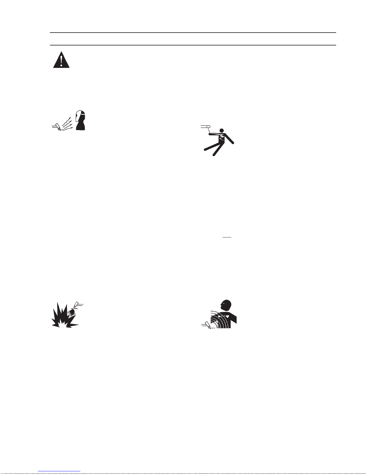
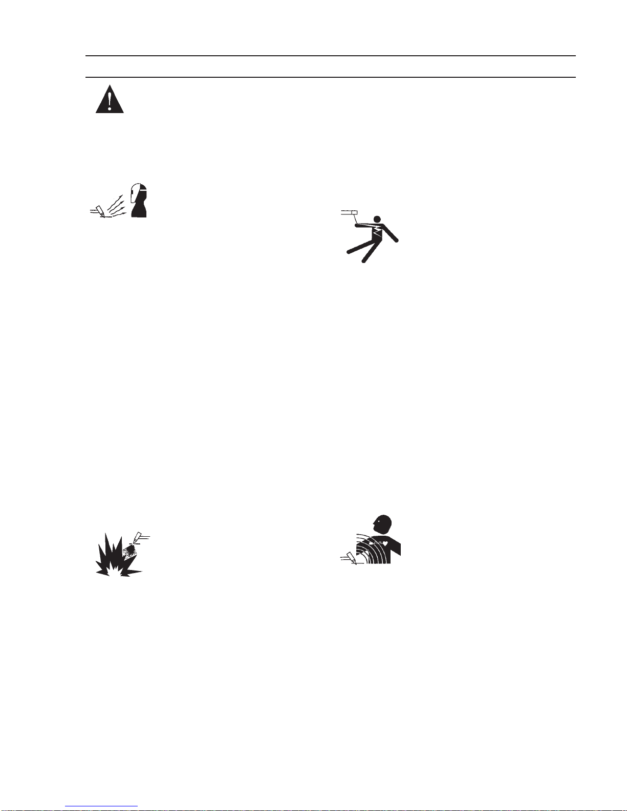
PROTEJASE USTED Y A LOS DEMAS--
Algunos procesos de soldadura, corte y
ranurado son ruidosos y requiren
protección para los oídos. El arco, como
el sol , emite rayos ultravioleta (UV) y otras radiaciones
quepueden dañarlapiely losojos.Elmetalcalientecausa
quemaduras. EL entrenamiento en el uso propio de los
equipos y sus procesos es esencial para prevenir
accidentes. Por lo tanto:
1. Utilicegafasdeseguridadconprotecciónalosladossiempreque
esté en el área de trabajo, aún cuando esté usando careta de
soldar, protector para su cara u otro tipo de protección.
2. Use una careta que tenga el filtro correcto y lente para proteger
sus ojos, cara, cuello, y oídos de las chispas y rayos del arco
cuando se esté operando y observando las operaciones. Alerte
a todas las personas cercanas de no mirar el arco y no
exponerse a los rayos del arco eléctrico o el metal fundido.
3. Use guantes de cuero a prueba de fuego, camisa pesada de
mangas largas, pantalón de ruedo liso, zapato alto al tobillo, y
careta de soldar con capucha para el pelo, para proteger el
cuerpo de los rayos y chispas calientes provenientes del metal
fundido. En ocaciones un delantal a prueba de fuego es
necesario para protegerse del calor radiado y las chispas.
4. Chispas y partículas de metal caliente puede alojarse en las
mangas enrolladas de la camisa , el ruedo del pantalón o los
bolsillos. Mangas y cuellos deberán mantenerse abotonados,
bolsillosalfrentedelacamisadeberánsercerradosoeliminados.
5. Protejaa otras personasdelosrayosdel arco ychispascalientes
con una cortina adecuada no-flamable como división.
6. Use careta protectora además de sus gafas de seguridad
cuando esté removiendo escoria o puliendo. La escoria puede
estarcaliente ydesprenderse convelocidad. Personas cercanas
deberán usar gafas de seguridad y careta protectora.
FUEGOYEXPLOSIONES--Elcalordelas
flamas y el arco pueden ocacionar
fuegos. Escoria caliente y las chispas
pueden causar fuegos y explosiones.
Por lo tanto:
1. Remueva todo material combustible lejos del área de trabajo o
cubralosmaterialesconunacobija apruebadefuego.Materiales
combustibles incluyenmadera,ropa,líquidosygasesflamables,
solventes, pinturas, papel, etc.
2. Chispas y partículas de metal pueden introducirse en las grietas
y agujeros de pisos y paredes causando fuegos escondidos en
otros niveles o espacios. Asegúrese de que toda grieta y agujero
esté cubierto para proteger lugares adyacentes contra fuegos.
3. No corte, suelde o haga cualquier otro trabajo relacionado hasta
quelapiezadetrabajoestétotalmentelimpiaylibrede substancias
que puedan producir gases inflamables o vapores tóxicos. No
trabaje dentro o fuera de contenedores o tanques cerrados.
Estos pueden explotar si contienen vapores inflamables.
4. Tenga siempre a la mano equipo extintor de fuego para uso
instantáneo, como por ejemplo una manguera con agua, cubeta
con agua, cubeta con arena, o extintor portátil. Asegúrese que
usted esta entrenado para su uso.
5. Nouseelequipofueradesurangodeoperación.Porejemplo,elcalor
causado por cable sobrecarga en los cables de soldar pueden
ocasionar un fuego.
6. Después de termirar la operación del equipo, inspeccione el área de
trabajo para cerciorarse de que las chispas o metal caliente
ocasionenunfuego más tarde.Tengapersonal asignado paravigilar
si es necesario.
7. Para información adicional , haga referencia a la publicación NFPA
Standard 51B, "Fire Prevention in Use of Cutting and Welding
Processes", disponible a través de la National Fire Protection
Association, Batterymarch Park, Quincy, MA 02269.
CHOQUE ELECTRICO -- El contacto con
las partes eléctricas energizadas y tierra
puede causar daño severo o muerte. NO
usesoldaduradecorrientealterna (AC)en
áreashúmedas,demovimiento confinado
en lugares estrechos o si hay
posibilidad de caer al suelo.
1. Asegúrese de que el chasis de la fuente de poder esté conectado
a tierra através del sistema de electricidad primario.
2. Conecte la pieza de trabajo a un buen sistema de tierra física.
3. Conecte el cable de retorno a la pieza de trabajo. Cables y
conductores expuestos o con malas conexiones pueden exponer
al operador u otras personas a un choque eléctrico fatal.
4. Useelequiposolamentesiestáenbuenascondiciones.Reemplaze
cables rotos, dañados o con conductores expuestos.
5. Mantenga todo seco, incluyendo su ropa, el área de trabajo, los
cables, antorchas, pinza del electrodo, y la fuente de poder.
6. Asegúrese que todas las partes de su cuerpo están insuladas de
ambos, la pieza de trabajo y tierra.
7. No se pare directamente sobre metal o tierra mientras trabaja en
lugares estrechos o áreas húmedas; trabaje sobre un pedazo de
madera seco o una plataforma insulada y use zapatos con suela
de goma.
8. Use guantes secos y sin agujeros antes de energizar el equipo.
9. Apage el equipo antes de quitarse sus guantes.
10. Use como referencia la publicación ANSI/ASC Standard Z49.1
(listado en la próxima página) para recomendaciones específicas
decomoconectarel equipo atierra.Noconfunda el cable desoldar
a la pieza de trabajo con el cable a tierra.
CAMPOS ELECTRICOS Y MAGNETICOS
- Son peligrosos. La corriente eléctrica
fluye através de cualquier conductor
causandoanivellocalCamposEléctricos
y Magnéticos (EMF). Las corrientes en el
área de corte y soldadura, crean EMF
alrrededor de los cables de soldar y las
maquinas. Por lo tanto:
1. Soldadores u Operadores que use marca-pasos para el corazón
deberán consultar a su médico antes de soldar. El Campo
Electromagnético (EMF) puede interferir con algunos marca-pasos.
2. Exponerse a campos electromagnéticos (EMF) puede causar otros
efectos de salud aún desconocidos.
3. Los soldadores deberán usar los siguientes procedimientos para
minimizar exponerse al EMF:
A. Mantengaelelectrodoyelcablealapiezadetrabajojuntos,hasta
llegar a la pieza que usted quiere soldar. Asegúrelos uno junto al
otro con cinta adhesiva cuando sea posible.
B. Nunca envuelva los cables de soldar alrededor de su cuerpo.
C. Nunca ubique su cuerpo entre la antorcha y el cable, a la pieza
de trabajo. Mantega los cables a un sólo lado de su cuerpo.
D. Conecte el cable de trabajo a la pieza de trabajo lo más cercano
posible al área de la soldadura.
E. Mantenga la fuente de poder y los cables de soldar lo más lejos
posible de su cuerpo.
SECTION 1 PRECAUCION DE SEGURIDAD

8
HUMO Y GASES -- El humo y los gases,
pueden causar malestar o daño,
particularmente en espacios sin ventilación.
Noinhaleelhumo ogases.Elgasdeprotección
puede causar falta de oxígeno. Por lo tanto:
1. Siempre provea ventilación adecuada en el
área de trabajo por medio natural o mecánico. No solde,
corte, o ranure materiales con hierro galvanizado, acero
inoxidable, cobre, zinc, plomo, berílio, o cadmio a menos
que provea ventilación mecánica positiva. No respire los
gases producidos por estos materiales.
2. No opere cerca de lugares donde se aplique substancias
químicas en aerosol. El calor de los rayos del arco pueden
reaccionar conlosvapores dehidrocarburo clorinado para
formar un fosfógeno, o gas tóxico, y otros irritant es.
3. Si momentáneamente desarrolla inrritación de ojos, nariz
o garganta mientras est á operando, es indicación de que
la ventilación no es apropiada. Pare de trabajar y tome
las medidas necesarias para mejorar la ventilación en
el área de trabajo. No continúe operando si el malestar
físico persiste.
4. Hagareferenciaalapublicación ANSI/ASC Standard Z49.1
(Vea la lista a continuación) para recomendaciones
específicas en la ventilación.
5. ADVERTENCIA-- Este producto cuando se utiliza para
soldaduras o cortes,produce humos
ogases,loscualescontienenquímicos
conocidos por el Estado de California
decausardefectosenelnacimiento,o
enalgunos casos,Cancer. (California
Health&SafetyCode§25249.5etseq.)
MANEJO DE CILINDROS-- Los
cilindros, si no son manejados
correctamente, pueden romperse y
liberar violentamente gases. Rotura
repentina del cilindro, válvula, o
válvuladeescape puedecausardaño
o muerte. Por lo tanto:
1. Utilize el gas apropiado para el proceso y utilize un
regulador diseñado para operar y reducir la presión del
cilindro de gas . No utilice adaptadores. Mantenga las
mangueras y las conexiones en buenas condiciones.
Observe las instrucciones de operación del manufacturero
para montar el regulador en el cilindro de gas comprimido.
2. Asegure siempre los cilindros en posición vertical y
amárrelos con una correa o cadena adecuada para
asegurarelcilindroal carro, transportes,tablilleros,paredes,
postes, o armazón. Nunca asegure los cilindros a la mesa
de trabajo o las piezas que son parte del circuito de
soldadura . Este puede ser parte del circuito elélectrico.
3. Cuando el cilindro no está en uso, mantenga la válvula del
cilindro cerrada. Ponga el capote de protección sobre la
válvula si el regulador no está conectado. Asegure y
mueva los cilindros utilizando un carro o transporte
adecuado. Evite el manejo brusco de los cilindros.
4. Localize los cilindros lejos del calor, chispas, y flamas.
Nunca establezca un arco en el cilindro.
5. Para información adicional, haga referencia a la publicación
CGA Standard P-1, "Precautions for Safe Handling of Com-
pressed Gases in Cylinders", disponible através del Com-
pressed Gas Association, 1235 Jefferson Davis Highway,
Arlington, VA 22202.
Las siguientes publicaciones, disponibles através de la
American Welding Society, 550 N.W. LeJuene Road, Miami,
FL 33126, son recomendadas para usted:
1. ANSI/ASC Z49.1 - "Safety in Welding and Cutting"
2. AWS C5.1 - "Recommended Practices for Plasma Arc
Welding"
3. AWS C5.2 - "Recommended Practices for Plasma Arc
Cutting"
4. AWS C5.3 - "Recommended Practices for Air Carbon Arc
Gouging and Cutting"
5. AWS C5.5 - "Recommended Practices for Gas Tungsten
Arc Welding“
6. AWS C5.6 - "Recommended Practices for Gas Metal Arc
Welding"“
7. AWS SP - "Safe Practices" - Reprint, Welding Handbook.
8. ANSI/AWSF4.1,"RecommendedSafePracticesforWeld-
ing and Cutting of Containers That Have Held Hazardous
Substances."
Significariesgo inmediato que, denoser
evadido, puede resultar inmediatamente
en serio daño personal o la muerte.
Significaelriesgodeunpeligropotencial
que puede resultar en serio daño per-
sonal o la muerte.
Significa el posible riesgo que puede
resultar en menores daños a la persona.
MANTENIMIENTO DEL EQUIPO -- Equipo
defectuoso o mal mantenido puede causar
daño o muerte. Por lo tanto:
1. Siempre tenga personal cualificado para efectuar l a
instalación, diagnóstico, y mantenimiento del equipo. No
ejecute ningún trabajo eléctrico a menos que usted esté
cualificado para hacer el trabajo.
2. Antes de dar mantenimiento en el interior de la fuente
de poder, desconecte la fuente de poder del suministro
de electricidad primaria.
3. Mantenga los cables, cable a tierra, conexciones, cable
primario, y cualquier otra fuente de poder en buen
estado operacional. No opere ningún equipo en malas
condiciones.
4. No abuse del equipo y sus accesorios. Mantenga el
equipo lejos de cosas que generen calor como hornos,
también lugares húmedos como charcos de agua , aceite
o grasa, atmósferas corrosivas y las inclemencias del
tiempo.
5. Mantenga todos los artículos de seguridad y coverturas
del equipo en su posición y en buenas condiciones.
6. Use el equipo sólo para el propósito que fue diseñado.
No modifique el equipo en ninguna manera.
INFORMACION ADICIONAL DE SEGURIDAD-
- Para más información sobre las prácticas de
seguridaddelosequiposde arcoeléctricopara
soldar y cortar, pregunte a su suplidor por una
copia de "Precautions and Safe Practices for
ArcWelding, CuttingandGouging-Form52-529.
SIGNIFICADODELOSSIMBOLOS--Según
ustedavanzaenlalecturadeestefolleto:
LosSímbolosSignifican¡Atención!¡Esté
Alerta! Se trata de su seguridad.
SECTION 1 PRECAUCION DE SEGURIDAD

9
coupes à l’arc, à moins de les recouvrir complètement
d’une bâche non-inflammable. Ce type de matériaux
comprend notamment le bois, les vêtements, la sciure,
l’essence, le kérosène, les peintures, les solvants, le
gaz naturel, l’acétylène, le propane et autres sub-
stances combustibles semblables.
b. Les étincelles ou les projections de métal incandescent
peuvent tomber dans des fissures du plancher ou dans
des ouvertures des murs et y déclencher une ignition
lente cachée. Veiller à protéger ces ouvertures des
étincelles et des projections de métal.
c. N’exécutez pas de soudures, de coupes, d’opérations
degougeageou autrestravaux àchaud à lasurface de
barils, bidons, réservoirs ou autres contenants usagés,
avantdeles avoirnettoyés detoute trace desubstance
susceptible de produire des vapeurs inflammables ou
toxiques.
d.En vued’assurerla préventiondes incendies,il convient
de disposer d’un matériel d’extinction prêt à servir
immédiatement, tel qu’un tuyau d’arrosage, un seau à
eau, un seau de sable ou un extincteur portatif.
e. Une fois le travail à l’arc terminé, inspectez le secteur
de façon à vous assurer qu’aucune étincelle ou
projection de métal incandescent ne risque de
provoquerultérieurementun feu.
3. CHOC ÉLECTRIQUE-- Le gougeageà l’arc et à l’arc au
plasma exige l’emploi de tensions à vide relativement
importantes; or, celles-ci risquent de causer des
dommages corporels graves et même mortels en cas
d’utilisation inadéquate. La gravité du choc électrique
reçu dépend du chemin suivi par le courant à travers le
corps humain et de son intensité.
a. Ne laissez jamais de surfaces métalliques sous tension
venir au contact direct de la peau ou de vêtements
humides. Veillez à porter des gants bien secs.
b. Si vous devez effectuer un travail sur une surface
métallique ou dans un secteur humide, veillez à assu-
rer votre isolation corporelle en portant des gants secs
et des chaussures à semelles de caoutchouc et en
voustenantsur uneplanche ouune plate-formesèche.
c. Mettez toujours à la terre le poste de soudage/coupage
en le reliant par un câble à une bonne prise de terre.
d. N’utilisez jamais de câbles usés ou endommagés. Ne
surchargez jamais le câble. Utilisez toujours un
équipementcorrectemententretenu.
e. Mettez l’équipement hors tension lorsqu’il n’est pas en
service. une mise à la masse accidentelle peut en effet
provoquerune surchauffede l’équipementet undanger
d’incendie. Ne pas enrouler ou passer le câble autour
d’une partie quelconque du corps.
f. Vérifiez si le câble de masse est bien relié à la pièce en
unpoint aussiproche quepossible dela zonede travail.
Le branchement des câbles de masse à l’ossature du
bâtiment ou en un point éloigné de la zone de travail
augmenteen effetle risquede passaged’un courantde
sortie par des chaînes de
AVERTISSEMENT: Ces règles de sécurité ont pour objet
d’assurer votre protection. Veillez à lire et à observer les
précautions énoncées ci-dessous avant de monter l’
équipement ou de commercer à l’utiliser. Tout défaut
d’observation de ces précautions risque d’entraîner des
blessures graves ou mortelles.
1. PROTECTION INDIVIDUELLE-- Les brûlures de la
peau et des yeux dues au rayonnement de l’arc
électrique ou du métal incandescent, lors du soudage
auplasmaou àl’électrode oulors dugougeage àl’arc,
peuvent s’avérer plus graves que celles résultant
d’une exposition prolongée au soleil. Aussi convient-il
d’observer les précautions suivantes:
a. Portez un écran facial adéquat muni des plaques
protectrices et des verres filtrants appropriés afin de
vous protéger les yeux, le visage, le cou et les oreilles
des étincelles et du rayonnement de l’arc électrique
lorsque vous effectuez des soudures ou des coupes
ou lorsque vous en observez l’exécution.
AVERTISSEZ les personnes se trouvant à proximité
de façon à ce qu’elles ne regardent pas l’arc et à ce
qu’elles ne s’exposent pas à son rayonnement, ni à
celui du métal incandescent.
b. Portez des gants ignifugés à crispins, une tunique
épaisse à manches longues, des pantalons sans
rebord,deschaussures àembout d’acieret uncasque
de soudage ou une calotte de protection, afin d’éviter
d’exposer la peau au rayonnement de l’arc électrique
ou du métal incandescent. ll est également
souhaitable d’utiliser un tablier ininflammable de façon
à se protéger des étincelles et du rayonnement
thermique.
c. Les étincelles ou les projections de métal incandescent
risquent de se loger dans des manches retroussées,
des bords relevés de pantalons ou dans des poches.
Aussi convient-il de garder boutonnés le col et les
manches et de porter des vêtements sans poches à
l’avant.
d. Protégez des étincelles et du rayonnement de l’arc
électrique les autres personnes travaillant à proximité
à l’aide d’un écran ininflammable adéquat.
e. Ne jamais omettre de porter des lunettes de sécurité
lorsque vous vous trouvez dans un secteur où l’on
effectue des opérations de soudage ou de coupage à
l’arc. Utilisez des lunettes de sécurité à écrans ou
verres latéraux pour piquer ou meûler le laitier. Les
piquetures incandescentes de laitier peuvent être
projetées à des distances considérables. Les
personnes se trouvant à proximité doivent également
porter des lunettes de protection.
f. Le gougeage à l’arc et le soudage à l’arc au plasma
produisent un niveau de bruit extrêmement élevé (de
100 à 114 dB) et exigent par conséquent l’emploi de
dispositifs appropriés de protection auditive.
2. PRÉVENTION DES INCENDES-- Les projections de
laitierincandescent oud’étincelles peuventprovoquer
degravesincendies aucontact dematériauxcombus-
tibles solides, liquides ou gazeux. Aussi faut-il ob-
server les précautions suivantes:
a. Éloigner suffisamment tous lesmatériaux combustibles
du secteur où l’on exécute des soudures ou des
9/97
SECTION 1 PRÉCAUTIONS DE SÉCURITÉ

10
levage, des câbles de grue ou divers chemins
électriques.
g. Empêchez l’apparition de toute humidité, notamment
sur vos vêtements, à la surface de l’emplacement de
travail, des câbles, du porte-électrode et du poste de
soudage/coupage. Réparez immédiatement toute
fuite d’eau.
4. VENTILATION-- La respiration prolongée des fumées
résultant des opérations de soudage/coupage, à
l’intérieur, d’un local clos, peut provoquer des mal-
aises et des dommages corporels. Aussi convient-il
d’observer les précautions suivantes:
a. Assurez en permanence une aération adéquate de
l’emplacement de travail en maintenant une ventila-
tion naturelle ou à l’aide de moyens mécaniques.
N’effectuez jamais de travaux de soudage ou de
coupage sur des matériaux de zinc, de plomb, de
beryllium ou de cadmium en l’absence de moyens
mécaniques de ventilation capables d’empêcher
l’inhalation des fumées dégagées par ces matériaux.
b. N’effectuez jamais de travaux de soudage ou de
coupage à proximité de vapeurs d’hydrocarbure
chloré résultant d’opérations voisines de
dégraissage ou de pulvérisation. La chaleur dégagée
ou le rayonnement de l’arc peut déclencher la
formation de phosgène -- gaz particulièrement
toxique -- et d’autres gaz irritants, à partir des
vapeurs de solvant.
c. Une irritation momentanée des yeux, du nez ou de la
gorge constatée au cours de l’utilisation de
l’équipement dénote un défaut de ventilation.
Arrêtez-vous de travailler afin de prendre les
mesures néces- saires à l’amélioration de la
ventilation. Ne poursuivez pas l’opération entreprise
si le malaise persiste.
d. Certaines commandes comportent des canalisations
où circule de l’hydrogène. L’armoire de commande
est munie d’un ventilateur destiné à empêcher la
formation de poches d’hydrogène, lesquelles
présentent un danger d’explosion; ce ventilateur ne
fonctionne que si l’interrupteur correspondant du
panneau avant se trouve placé en position ON
(Marche). Veillez à manœuvrer cette commande en
vérifiant si le couvercle est bien en place, de façon à
assurer l’efficacité de la ventilation ainsi réalisée. Ne
jamais débrancher le ventilateur.
e. Les fumées produites par l’opération de soudage ou
de coupage peuvent s’avérer toxiques. Aussi est-il
nécessaire de disposer en permanence d’un
dispositif adéquat de ventilation de type aspirant,
afin d’élimi-ner du voisinage de l’opérateur tout
dégagement de fumée visible.
f. Consultez les recommandations particulières en
matière de ventilation indiquées à l’alinéa 6 de la
norme Z49.1 de l’AWS.
5. ENTRETIEN DE L’ÉQUIPEMENT-- Un équipement
entretenu de façon défectueuse ou inadéquate risque
non seulement de réaliser un travail de mauvaise
qualité mais, chose plus grave encore, d’entraîner des
dommages corporels graves, voire mortels en
déclenchant des incendies ou des chocs électriques.
Observez par conséquent les précautions suivantes:
a. Efforcez-vous de toujours confier à un personnel qua-
lifié l’installation, le dépannage et l’entretien du poste
de soudage et de coupage. N’effectuez aucune
réparation électrique sur l’équipement à moins d’être
qua-lifié à cet effet.
b. Ne procédez jamais à une tâche d’entretien
quelconque à l’intérieur du poste de soudage/
coupage, avant d’avoir débranché l’alimentation
électrique.
c. Maintenez en bon état de fonctionnement les câbles,
le câble de masse, les branchements, le cordon
d’alimentation et le poste de soudage/coupage.
N’utilisez jamais le poste ou l’équipement s’il
présente une défectuosité quelconque.
d. Prenez soin du poste de soudage et de coupage et
des équipements accessoires. Gardez-les à l’écart
des sources de charleur, notamment des fours, de
l’humidité, des flaques d’eau maintenez-les à l’abri
des traces d’huile ou de graisse, des atmosphères
corrosives et des intempéries.
e. Laissez en place tous les dispositifs de sécurité et
tous les panneaux de l’armoire de commande en
veillant à les garder en bon état.
f. Utilisez le poste de soudage/coupage conformément
à son usage prévu et n’effectuez aucune modifica-
tion.
6. INFORMATIONS COMPLÉMENTAIRES RELATIVES
À LA SÉCURITÉ--
Pour obtenir des informations complémentaires sur
les règles de sécurité à observer pour le montage et
l’utilisation d’équipements de soudage et de coupage
électriques et sur les méthodes de travail
recommandées, demandez un exemplaire du livret N°
52529 “Precautions and Safe Practices for Arc
Welding, Cutting and Gouging” publié par ESAB.
Nous conseillons également de consulter les publica-
tions sui-vantes, tenues à votre disposition par
l’American Welding Society, 550 N.W. LeJuene Road,
Miami, FL 32126:
a. “Safety in Welding and Cutting” AWS Z49.1
b. “Recommended Safe Practices for Gas-Shielded Arc
Welding “AWS A6. 1.
c. “Safe Practices for Welding and Cutting Containers
That Have Held Combustibles” AWS-A6.0.
d. “Recommended Safe Practices for Plasma Arc
Cutting” AWS-A6. 3.
e. “Recommended Safe Practices for Plasma Arc
Welding” AWS-C5. 1.
f. “Recommended Safe Practices for Air Carbon Arc
Gouging and Cutting” AWS-C5. 3.
g. “Code For Safety in Welding and Cutting”
CSA-Standard W117. 2.
9/97
SECTION 1 PRÉCAUTIONS DE SÉCURITÉ

11
Table 2-1. Specifications for MultiPower 460 Pulse
1. SAFETY
Before the MultiPower 460 Pulse power source is put into operation, the
safetysectionatthefrontofthismanualshouldbereadcompletely. Thiswill
help avoid possible injury due to misuse or improper installation.
The definitions relating to the:
safetynotations aredescribed atthe endof theSafety Sectioninthefrontof
this manual — read them and their specific text references carefully.
2. DESCRIPTION
This manual has been prepared for use by an experienced operator. It
provides information to familiarize the operator with the design, installation
andoperationoftheMultiPower460Pulsepowersource. DONOTattemptto
installoroperatethisequipmentuntilyouhavereadandfullyunderstoodthese
instructions. Theinformationpresentedhereshouldbegivencarefulconsid-
eration to ensure proper installation and optimum weld performance of this
equipment.
OPEN CIRCUIT VOLTAGE (U2) 80V DC Max.
RATED
OUTPUT
DUTYCYCLE 60% 100%
Current (I2) 500 A 450 A
Voltage (U2) 40 V 38 V
RATED
INPUT 3 Phase
60 Hz
Volts (U1) Current (I1) Flat Current (I1) Flat
208/230 V 76 A 66 A
460 V 38 A 33 A
575 V 31 A 26 A
50 Hz 220 V 79 A 68 A
400 V 43 A 37 A
Power Factor at Rated Output 89%
Welding Range 10 A/12 V - 500 A/40 V
Auxiliary Power 115 V ac @ 10 A, 60 Hz
PHYSICALSPECIFICATIONS
Height (without lift eye) 25.0" (62.2 cm)
Width 18.8" (48.3 cm)
Depth 32.5" (81.9 cm)
Net Weight 322lbs (146 kg)
Shipping Weight 375lbs (170 kg)
SECTION 2 DESCRIPTION

12
TheMultiPower460Pulseisamulti-processpowersourcedesignedforMig
short circuiting, spray and pulse spray transfer (GMAW), flux core (FCAW),
Tig (GTAW), and stick (SMAW) welding and air carbon arc cutting/gouging
(CAC-A) applications. Table 1-1 outlines the electrical and physical specifi-
cations.
A. POWER SOURCE
Thepowersourceisaconstantcurrent(CC)andconstantvoltage(CV),three
phase, secondary chopper dc design with solid state contactor and control
circuitry. Itprovidesthevolt-amperecharacteristicsdesired forconventional
MIG and flux core arc welding in the CV (constant voltage) mode or stick
welding, Tig (GTAW) and arc gouging in the CC (constant current) mode.
Features
• AutoFan-TheMultiPower460Pulsefanwillrunwhenthepowersource
isfirstpoweredupforapproximately30seconds. Thefanwillstartagain
whenweldingbeginsandisatacurrentlevelabove50amps. Thefanwill
remain running for 6 minutes after welding stops and then shut down
automatically.
• Stainlesssteel framefor envirornmentaldurability.
• Durable side and top panels will not corrode.
• 100% duty cycle output at 460 amps.
• Compatible with all ESAB 42VAC wire feeders.
• Compatible with all the off the arc feeders.
B. VOLT-AMPERECHARACTERISTICS
ThecurvesshowninFigure2-2representthestaticvolt-amperecharacteristics
forthepowersource. Theslantofthesecurvesisreferredtoasthe"slope"and
isgenerallydefinedasthevoltagedropper100amperesofcurrentuse.These
curves show the output voltage available at any given output current from
theminimumto themaximum settingof thevoltage/current control.
SECTION 2 DESCRIPTION
Figure 2-2 - MultiPower 460 Volt-Ampere Curves

13
Figure 2-3. Pulse Control Panel
SECTION 2 DESCRIPTION
C.CONTROLPANELDESCRIPTION
(RefertoFigures2-3and2-4)
1. FAULT LAMP
The RED fault light on the MultiPower 460 Pulse front panel indicates a
problem with set-up parameters. A "Steady" light "On" indicates there is
no program for the material and wire diameter selected. A "Blinking"
light indicates the wire feed speed is out of the recommended range.
2. TEMPERATURELAMP
TheTEMPlampilluminatesifanovertemperatureconditionoccurswithinthe
MultiPower 460 Pulse power source. This condition may be caused by
excessivedutycycleorover-currentconditions.Whenanovertemperature
conditionoccurs,theweldingoutputisturnedoffandtheunitmustbeallowed
tocool.The machinewill automaticallyreset when thetemperature fallsto
asafelevel.
3. PROCESSSELECTORSWITCH
Thethreepositionprocessselectorswitchislocatedintheupperright-hand
cornerofthecontrolpanel. Theprocessselectorswitchpositionprovidesthe
visualindicationofwhichweldprocess(Mig,Tigorstick)hasbeenselected.
4. DIGITAL DISPLAY/METERS (WFS, AMPS & VOLTS)
The digital displays located on the left side of the control panel are
multifunctional depending on the welding process being used. The top
displayreadswirefeedspeedininchesperminuteintheMIGPRESETmode
andweldingcurrent (amps)in the TIGand STICKPRESET mode. During
weldingbothdisplaysindicateaverageweldingcurrentandaveragewelding
voltage.
Fault
Lamp
WFS-IPM
Lamp Amps
Lamp
Digital Meter
Amps/WFS
Power “ON”
Lamp
Temperature
Lamp
Digital Meter
Volts

14
DESCRIPTION
SECTION 2
WhenusingaDuraDrive4-30orDuraDrive4-48WireFeeder,thewirefeed
speed is displayed in inches per minute (IPM) in the top display when the
PRESET button is pressed and the wire speed adjustment knob on the
wirefeederisrotated. TheWFS LEDbesidethetopdisplaymeterwilllight
whenthe displayis showingwire feedspeed.
5. VOLTAGE / CURRENT / TRIM
The arc voltage is controlled with this knob when the WELD PROCESS
selector switch is in the MIG position. The Mig arc voltage can be preset
by pressing the PRESET button and reading the arc volts in the bottom
digital display while rotating this knob.
The arc current is controlled with this knob when the WELD PROCESS
SWITCHisintheTIGorSTICKposition. Theweldingcurrentcanbepreset
inamperesbypressingthePRESETbuttonandreadingthecurrent(amps)
inthetopdigitaldisplaywhilerotatingthisknob. Theaverageweldcurrent
will be displayed during welding.
ForMIGPULSE welding,thearclength(arc voltage)iscontrolledwith this
knob. The WELD PROCESS switch is placed in the MIG position and the
modeswitchisplacedinthePULSEposition. Theknobshouldbeplaceat
the12o'clockpositionasthesynergicpresetforthewirefeedspeed,WIRE
TYPE and WIRE DIAMETER choosen by the operator using the PULSE
SELECTIONswitches. Thearclengthcanthenbeadjusted byturningthe
knobclockwisetoincreasethearclengthorcounterclockwisetodecrease
the arc.
6. PANEL/REMOTE SWITCH
WiththisswitchinthePANEL position,outputvoltageintheCVmodeand
theoutputcurrentintheCCmodearecontrolledbyadjustingtheVOLTAGE/
CURRENT/TRIM knob on the power source control panel to the desired
output. IntheREMOTEposition,outputiscontrolledusingaremotecontrol
devicesuch asa wirefeeder, handcontrol orfootcontrol.
NOTE:
A DuraDrive Wire Feeder is required to
preset wire feed speed.
Figure 2-4. Pulse Control Panel
Preset
Button
Mode
Switch Panel/
Remote
Current
Voltage Material Selection
(Pulse)
Wire Diameter
Selector (Pulse)
Weld Process
Switch
Inductance

15
Figure 2-5. MultiPower 460 Pulse
7. INDUCTANCETRIM
ThiscontrolisusedonlyintheSTANDARDmodeandisdeactivatedintheTIG,
STICKandPULSEmodes.
Inductanceisusedtooptimizeshortcircuitingarcperformancebychangingthe
currentriseandfalltime ofeach shortcircuit. Thisresultsinimprovedspatter
control, weld bead wetting and arc stability. The short circuiting Mig arc
performancewillchangefromahighshortcircuitfrequency,fastreactingarc,
toalowershortcircuitfrequency,softandlessspatteringarcasthedialisturned
clockwise. Theoptimizedarcperformancewillvarydependingonshieldinggas,
wire type and wire diameter. The operator can adjust this control to optimize
weldingcharacteristics.
8. STANDARD/PULSESWITCH
Thisswitchenables theMigpulseoperationmode. When thisswitchisinthe
MIG PULSE position, the pulse parameters are determined by the WIRE
TYPE and WIRE DIAMETER position on the PULSE SELECTION switches.
9. PULSE SELECTION SWITCHES
WIRE TYPE
Use this switch to select the WIRE TYPE installed on the wire feeder. The
position of this switch and the WIRE DIAMETER switch selects the pulse
parameters to be used during welding in the Mig pulse mode.
WIRE DIAMETER
Use this switch to select the WIRE DIAMETER installed on the wire feeder.
The position of this switch and the WIRE TYPE switch selects the pulse
parameters to be used during welding in the Mig pulse mode.
D. POWER SOURCE FRONT PANEL DESCRIPTION
(RefertoFigure2-5)
DESCRIPTION
SECTION 2
MainPower
On/OffSwitch
Output
Connections
RemotePendant
Connection
ContactorOn/Off
Switch
CircuitBreakers
CB1 & 2
ControlPanel
115Vac
10 Amps
Receptacle
19-PinWire
FeederConnection

16
DESCRIPTIONSECTION 2
1. POWER ON/OFF SWITCH & LAMP
Themainpowerswitchislocatedontherightfrontpanelofthepowersource.
Thisswitchenergizesthemaintransformer,controlcircuitryandilluminates
thePower“ON”lamp.
2. WIREFEEDERCONTROLRECEPTACLE
This19-pinreceptacle (J1)acceptsthecontrol cablefromthewirefeeder
andhandlesallthecontrolsignalsneededtooperatea42Vacwirefeeder.
3. REMOTE CONTROL RECEPTACLE
This receptacle (J2) is provided for an optional 14-pin control cable from
the optional remote pendant, Tig torch control or foot control . This
receptacle is operative only if the PANEL/REMOTE switch on the power
source front panel is in the "REMOTE" position.
4. CONTACTOR "ON/OFF" SWITCH
This switch provides manual control of the welding contactor when the
PROCESSswitchonthecontrolpanelisintheMIGposition(CVwelding).
An example of when to use this switch is when CV carbon arc gouging is
needed or an "Off the Arc" wire feeder with secondary contactor is
operated in the CV mode.
5. AUXILIARY115VACRECEPTACLE
A115 Vacreceptacle isprovided tosupply powerto accessoriessuch as
awatercooler,heatedCO2regulator, orsmallhandtools. Thereceptacle
is rated 115 Vac / 10 amps with a floating neutral.
6. 42VAC AND 115 VAC CIRCUIT BREAKER (CB1 & CB2)
These resetable 10 amp circuit breakers (CB1 & CB2) protect the 42 volt
wirefeeder/controland115voltauxiliaryreceptacle circuitryagainst over
current. (Table 7-1 provides troubleshooting information).
E. OPTIONAL ACCESSORIES
1. REMOTEHANDCONTROL(PN-0558002871)
Thispendant(Figure2-6)providesremoteoutputcontrolandacontactor
closure switch to close the contactor making the output terminals “hot”.
ThePANEL/REMOTEswitchontheMultiPower460Pulsecontrolpanel
mustbeplacedintheREMOTEpositionwhenusingthisaccessory. The
pendanthasthecapabilityto changeweldprocessesaswell asadaptto
digitalandanalogwirefeeders.
2. TR-29 TRUCK KIT (PN - 37924)
This truck kit provides complete mobility of the power source. The kit
consists of front castors, rear cylinder rack and wheels, gas cylinder
bracket, cylinder chain, and pull handle.
3. SWIVEL MOUNT KIT (PN - 36172)
Thiskitallowsthewire feedertobeplacedonaninsulated swivelpost on
topofthepowersource. Thefeedercanfreelyrotate,relievingpotentialwire
feedproblemscausedbysharpbendsintheguncablewhile,atthesame
time,increasing the radiusof theworking area.

17
Figure2-6.RemoteControlPendant
DESCRIPTION
SECTION 2
NOTE
If a Foot Control or Remote Hand Control
is used for continuous current control,
place the PANEL/REMOTE switch in the
PANELPOSITIONandsetthePanelCur-
rent knob to the maximum desired weld
current. The remote device will then con-
trolthecurrentbetweenminimumandthe
maximum setting preset (proportional
current control). Maximum Tig weld cur-
rent is 525 amps.
NOTE
The FC-5B foot control or TC-2B hand
control must be used with the MP-460 for
remote current Tig current control.
NOTE
If the MP-460 PANEL/REMOTE switch
is left in the REMOTE position when Tig
welding while using a remote current
control device, the current range will
be full scale or 10 to 400 Amps.
Limiting the the Maximum weld current
on the MP-460 front panel is defeated.
NOTE
When using a DuraDrive wire feeder
(or any wire feeder with Remote
Voltage control from the feeder front
panel) connected simultaneously with
a remote current control Tig device
(FC-5B or TC-2B), proportional control
of the TIG remote current will be
controlled by the position of the feeder
voltage control knob when the PANEL/
REMOTE switch is in the REMOTE
position. When in the PANEL position
the maximum current of the remote
device is controlled by the MP-460
front panel current control preset.
NOTE
When using the MP-460 Pulse, the
STANDARD/PULSE switch must be in
the STANDARD position for
proportional current control using a TIG
remote current device (FC-5B or TC-
2B).
4.TIGREMOTECONTROLS
ThefollowingRemotecontrolsareavailablefortheTigwelding:
FC-5BEHDFootControl 33841
FC-5BFootControl 33838
TC-2BTorchMountControl 33839
TC-3ATorchMountOn/Offonly:
(HW-9, 17, 20, 20A & 24) 35783
(HW-18&26R) 36680

18
DESCRIPTION
SECTION 2

19
Table 3-1. Recommended Sizes for Input
ConductorsandLineFuses
*Sized per National Code for 80 °C rated copper conductors @ 30 °C ambient. Not more than three
conductors in raceway or cable. Local codes should be followed if they specify sizes other than those
listedabove.
3. INSTALLATION
A. LOCATION
A proper installation site is necessary for the power source to provide
dependableservice.Aproperinstallationsitepermitsfreedomofairmovement
throughtheunitwhileminimizingexposuretodust,dirt,moisture,andcorrosive
vapors.Aminimumof18inches(46cm)isrequiredbetweenthesideandrear
panelsof thepowersourceandthe nearestobstruction.
The selected site should also allow easy removal of the power source outer
enclosure for maintenance. See Table 2-1 for overall dimensions of the unit.
B. RECEIVING, UNPACKING AND PLACEMENT
When requesting information concerning this equipment, it is essential that
Itemnumber,SerialnumberandModelnumberoftheequipmentbesupplied.
a. Uponreceipt,removeallpackingmaterialandcarefullyinspectforany
damagethatmayhaveoccurredduringshipment. Anyclaimsforloss
or damage that may have occurred in transit must be filed by the
purchaser with the carrier. A copy of the bill of lading and freight bill
willbe furnishedbythecarrieron request.
b. Remove the power source from the container. Remove all packing
materials. Check the container for any loose parts.
c. Check air passages at front and rear of cabinet, making sure that
packing material has not obstructed air flow through the power
source.
d. Installtheliftingboltfurnishedwiththepowersourcesintothetopofthe
unit.
e. After selecting an installation site, place the power source in the
desiredlocation. Theunit maybe liftedeither by usingthe liftingbolt
or by forklift truck. If a forklift is used for lifting the unit, be sure that
the lift forks are long enough to extend completely under the base.
C. PRIMARY (INPUT) ELECTRICAL CONNECTION
Thispowersourceisathree-phaseunitandmustbeconnectedtoathree-phase
powersupply.Itisrecommendedthattheunitbeoperatedonadedicatedcircuit
topreventimpairmentofperformanceduetoanoverloadedcircuit.
INSTALLATION
SECTION 3
For lifting purposes and for keeping
dust, moisture, and other foreign ma-
terial from entering the power source,
the lifting eyebolt must be fully tight-
ened with a tool.
Do not use filters on this unit as they
would restrict the volume of intake air
required for proper cooling. Output
ratings on this unit are based on an
unobstructed supply of cooling air
drawn over its internal components.
Warranty is void if any type of filtering
device is used.
Rated Input
@ 100% Duty Cycle Input &
GND
Conductor*
CU/AWG
Fuse
Size
Amps
Volts Amps
220
230
400
460
575
68
66
37
33
26
No. 6
No. 6
No. 8
No. 8
No. 10
100
100
60
60
50

20
1. Theprimarypowerleadsmustbeinsulatedcopperconductors.Three
powerleadsandonegroundwirearerequired. Eitherrubbercovered
cable or conduit (flexible or solid) may be used. Table 3-1 provides
recommendedinput conductorsand linefuse sizes.
ELECTRIC SHOCK CAN KILL! Before
making electrical input connections
to the power source, "Machinery
Lockout Procedures" should be em-
ployed. If the connections are to be
made from a line disconnect switch,
place the switch in the off position
and padlock it to prevent inadvert-
ent tripping. If the connection is
made from a fuse box, remove the
corresponding fuses and padlock
the box cover. If it is not possible to
use padlocks, attach a red tag to the
line disconnect switch (or fuse box)
warning others that the circuit is
being worked on.
The chassis must be connected to
an approved electrical ground. Fail-
ure to do so may result in electrical
shock, severe burns or death.
Typical Installation - User Supplied
3 Phase Fused Power Disconnect
Box with Receptacle and Plug
INSTALLATION
SECTION 3
Other manuals for MultiPower 460 Pulse
2
Table of contents
Other ESAB Welding System manuals

ESAB
ESAB Origo Mig 410 User manual

ESAB
ESAB Rogue EMP 210 PRO User manual

ESAB
ESAB ESP-50 User manual

ESAB
ESAB 453cc User manual

ESAB
ESAB ST-21 User manual

ESAB
ESAB Cutmaster 100 User manual

ESAB
ESAB ESABMig C420 User manual

ESAB
ESAB BOMBARDIER SVI-450i User manual

ESAB
ESAB LPH 120 User manual

ESAB
ESAB EPP-200 User manual

ESAB
ESAB EMP 215ic User manual

ESAB
ESAB A6S Compact 300 User manual

ESAB
ESAB MECHTIG 160 User manual

ESAB
ESAB EM235ic User manual

ESAB
ESAB Warrior 500i CC/CV User manual

ESAB
ESAB Rogue ES 180i Pro User manual

ESAB
ESAB THERMAL DINAMICS CUTMASTER 60i User manual

ESAB
ESAB OCF 2L User manual

ESAB
ESAB ST-21M User manual

ESAB
ESAB WARRIOR EDGE 500 User manual