Ritmo STARGUN LINK Manual
MANUALE ORIGINALE: ITALIANO
Rev.:0 September 6th , 2021
MU001953
STARGUN LINK
ISO9001 Quality System
I
MANUALE D’USO E MANUTENZIONE
OPERATION AND MAINTENANCE HANDBOOK
EN
MANUAL DE USO Y MANTENIMIENTO
E
F
MANUEL D’UTILISATION ET D’ENTRETIEN
D
BEDIENUNGS UND WARTUNGSANLEITUNG
RO
MANUAL DE UTILIZARE ŞI ÎNTREŢINERE

2
3
1. CAMPO DI UTILIZZO ..................................................................................4
2. CARATTERISTICHE TECNICHE ....................................................................4
3. DIMENSIONI..............................................................................................4
4. DESCRIZIONE DELLe PARTI ........................................................................4
5. SICUREZZA ................................................................................................4
6. CRITERI GENERALI DI SALDATURA.............................................................5
7. USO...........................................................................................................7
PREPARAZIONE ESTRUSORE.....................................................................7
SOSTITUZIONE PATTINO .......................................................................7
COLLEGAMENTO ELETTRICO.................................................................7
RISCALDAMENTO..................................................................................7
IMPOSTAZIONE TEMPERATURA ARIA ...................................................7
IMPOSTAZIONE TEMPERATURA ESTRUSO ............................................8
VERIFICHE ................................................................................................8
ISTRUZIONI OPERATIVE............................................................................8
GEOMEMBRANE ...................................................................................9
SPEGNIMENTO.........................................................................................9
MENÙ IMPOSTAZIONI GENERALI .............................................................9
REGOLAZIONE FLUSSO ARIA ...............................................................10
8. MANUTENZIONE.....................................................................................10
9. MALFUNZIONAMENTI.............................................................................11
1. FIELD OF APPLICATION ...........................................................................12
2. TECHNICAL FEATURES.............................................................................12
3. DIMENSIONS...........................................................................................12
4. PARTS .....................................................................................................12
5. SAFETY CRITERIA.....................................................................................12
6. WELDING CRITERIA.................................................................................13
7. USE .........................................................................................................15
SETUP ....................................................................................................15
SHOE REPLACEMENT ..........................................................................15
MAINS CONNECTION..........................................................................15
WARM UP...........................................................................................15
AIR TEMPERATURE SETTING...............................................................15
EXTRUDATE TEMPERATURE SETTING .................................................16
CHECKS ..................................................................................................16
OPERATING INSTRUCTIONS ...................................................................16
LINERS –GEOTEXTILES........................................................................17
SHUTDOWN...........................................................................................17
SETTINGS MENU ....................................................................................17
AIR-FLOW SETTING.............................................................................18
8. MAINTENANCE .......................................................................................18
9. TROUBLESHOOTING................................................................................19
1. ANWENDUNGSBEREICH..........................................................................20
2. TECHNISCHE EIGENSCHAFTEN ................................................................20
3. ABMESSUNGEN.......................................................................................20
4. BESCHREIBUNG DER BAUTEILE ...............................................................20
5. SICHERHEITSKRITERIEN...........................................................................20
6. ALLGEMEINE SCHWEIßKRITERIEN ...........................................................21
7. GEBRAUCHSANWEISUNG........................................................................23
VORBEREITUNG DES EXTRUDERS...........................................................23
ELEKTRISCHE ANSCHLÜSSE .................................................................23
WARM UP...........................................................................................23
TEMPERATUREINSTELLUNG...................................................................23
EINSTELLUNG DER LUFTTEMPERATUR................................................23
TEMPERATUREINSTELLUNG der Plastifizierungskammer....................24
ÜBERPRÜFUNG ......................................................................................24
OPERATIVE ANWEISUNGEN ...................................................................24
DICHTUNGSBAHNEN...........................................................................25
AUSSCHALTEN........................................................................................25
MENÜ FÜR ALLGEMEINE EINSTELLUNGEN.............................................25
EINSTELLUNG DES LUFTSTROMS.........................................................26
8. WARTUNG ..............................................................................................26
9. FEHLERMEDLUNGEN...............................................................................27
1. RANGO DE TRABAJO...............................................................................28
2. CARACTERÍSTICAS TÉCNICAS ..................................................................28
3. DIMENSIONES Y PARTES .........................................................................28
4. PARTES ...................................................................................................28
5. CRITERIOS DE SEGURIDAD ......................................................................28
6. CRITERIOS GENERALES DE SOLDADURA..................................................29
7. INSTRUCCIONES DE USO.........................................................................31
PREPARACIÓN DE LA EXTRUSORA .........................................................31
CONEXIÓN ELÉCTRICA ........................................................................31
CALENTAMIENTO ...............................................................................31
ESTABLECER TEMPERATURA DELL’AIRE..............................................31
ESTABLECER TEMPERATURA PLASTIFICACIÓN....................................32
VERIFICACIONES ....................................................................................32
INSTRUCCIONES OPERATIVAS................................................................32
GEOMEMBRANAS ..............................................................................33
APAGADO ..............................................................................................33
MENÚ de CONFIGURACIÓN GENERAL ...................................................33
AJUSTE DE FLUJO DE AIRE ..................................................................34
8. MANTENIMIENTO...................................................................................34
9. MALFUNCIONAMIENTO..........................................................................35
1. PLAGE D’UTILISATION .............................................................................36
2. CHARACTERISTIQUES TECHNIQUES.........................................................36
3. ENCOMBREMENT ...................................................................................36
4. COMPOSANTS.........................................................................................36
5. CRITERES DE SECURITE............................................................................36
6. CRITERES GENERAUX DE SOUDURE.........................................................37
7. INSTRUCTIONS D’USAGE.........................................................................39
PREPARATION DE L’EXTRUDEUSE ..........................................................39
REMPLACEMENT BEC..........................................................................39
CONNEXION ELECTRIQUE ...................................................................39
CHAUFFAGE........................................................................................39
TEMPÉRATURE DE L’AIR......................................................................39
TEMPÉRATURE DE L’EXTRUDÉE ..........................................................40
VERIFICATIONS ......................................................................................40
MODE D'EMPLOI....................................................................................40
GEOMEMBRANES ...............................................................................41
ARRETER LA SOUDEUSE .........................................................................41
MENU DES CONFIGURATIONS GENERALES ............................................41
RÉGLAGE DU DÉBIT D'AIR ...................................................................42
8. ENTRETIEN..............................................................................................42
9. MAUVAIS FONCTIONNEMENT ................................................................43
1. UTILIZARE ...............................................................................................44
2. SPECIFICATII............................................................................................44
3. DIMENSIUNI ...........................................................................................44
4. PIESE.......................................................................................................44
5. SIGURANȚĂ.............................................................................................44
6. CRITERII GENERALE DE SUDARE..............................................................45
7. INSTRUCȚIUNI DE UTILIZARE ..................................................................47
PREGĂTIREA EXTRUDĂRII ......................................................................47
ÎNLOCUIREA BACȘIȘULUI (TAMPONULUI)...........................................47
CONEXIUNE ELECTRICĂ ......................................................................47
ÎNCĂLZIRE...........................................................................................47
SETAREA TEMPERATURA AERULUI .....................................................47
SETAREA TEMPERATURII EXTRUDATE ................................................48
CONTROALE...........................................................................................48
INSTRUCȚIUNILE ....................................................................................48
GEOMEMBRANE.................................................................................49
OPRIREA / RĂCIREA ...............................................................................49
MENIUL SETĂRI GENERALE....................................................................49
REGLAREA FLUXULUI DE AER..............................................................50
8. ÎNTREȚINERE...........................................................................................50
9. DEFECŢIUNI ............................................................................................51

4
IT
Egregio Cliente,
La ringraziamo per aver scelto una macchina della linea di prodotti Ritmo.
Questo manuale è stato redatto con lo scopo di illustrare le caratteristiche
e le modalità di utilizzo del modello di estrusori serie STARGUN LINK che ha
acquistato. In esso sono contenute tutte le informazioni e le avvertenze
necessarie per un uso appropriato e sicuro dell’apparecchio da parte di
operatori professionisti. Raccomandiamo di leggerlo in tutte le sue parti
prima di accingersi all’uso della macchina e di conservarlo per consultazioni
future e/o eventuali successivi utilizzatori. Siamo certi che Le sarà facile
familiarizzare con la Sua nuova attrezzatura e che potrà servirsene a lungo
con piena soddisfazione.
1. CAMPO DI UTILIZZO
LO STARGUN LINK è un mini estrusore portatile adatto alla saldatura per
apporto di materiale termoplastico come il Polietilene (PE), il Polipropilene
(PP).
Esempi di saldature realizzabili
a “V”
a “DV”
a 90°
D_ K
a sovrapposizione
Ad angolo esterno
2. CARATTERISTICHE TECNICHE
LINK 20
LINK 30
LINK 40
Filo utilizzabile
3-4 mm
3-4-5 mm
4-5 mm
Capacità di
estrusione
2,2 Kg/h
3,2 Kg/h
4 Kg/h
Materiali saldabili
PE, PP, PVDF
PE, PP, PVDF
PE, PP
Alimentazione
230V50Hz
230V50Hz
110V60Hz
230V50Hz
Potenza totale
assorbita
3,1 KW
3,2 KW 230
V
2,7 KW 110V
3,7 KW
Rumore
LwA = 78 dBA
Peso complessivo
6,5 Kg
6,8 Kg
7,3 Kg
3. DIMENSIONI
a pagina 52
4. DESCRIZIONE DELLE PARTI
a pagina 52
5. SICUREZZA
L’utilizzo degli estrusori serie STARGUN LINK è destinato esclusivamente a
personale addestrato e qualificato.
Adibire la macchina esclusivamente alla funzione descritta nel capitolo-2
“Campo di utilizzo” e secondo le Istruzioni di uso e manutenzione. Qualsiasi
altro impiego è da considerarsi improprio ed è vietato, poiché può causare
lesioni agli operatori, a terzi, e/o danni alla macchina o ad altri oggetti.
Sostituire prontamente qualsiasi componente usurato o danneggiato con
ricambi originali Ritmo.
Qualsiasi intervento di riparazione sulla macchina deve essere effettuato da
personale esperto e qualificato.
Presente su:
MOTORE E SOFFIANTE
PERICOLO DI
FOLGORAZIONE
VERIFICA
COLLEGAMENTO
A TERRA
Verificare l’efficienza del collegamento a terra.
Verificare che le caratteristiche elettriche della macchina corrispondano
a quelle della fonte di alimentazione.
Il quadro da cantiere o il gruppo elettrogeno ai quali si collega la
macchina devono essere dotati di interruttore differenziale ad alta
sensibilità (I=30mA).
Le prese sul quadro devono appartenere al tipo IEC 309 con grado
minimo di protezione IP44.
Non esporre la macchina alla pioggia o ad altri liquidi.
Assicurarsi che le protezioni isolanti (ad esempio i guanti) siano sempre
perfettamente asciutte.
Non esporre i cavi ad agenti chimici o a sollecitazioni meccaniche (come
passaggio di veicoli e pedoni, contatto con oggetti taglienti, strattoni
ecc.).
Scollegare la presa di alimentazione dalla rete elettrica a lavori terminati
o sospesi.
Prima di utilizzare la macchina controllare l’integrità dei singoli
componenti, in particolare parti isolanti, cavi, passacavi e pressacavi.
Effettuare una pulizia accurata della macchina altermine del suo utilizzo.
Non usare solventi, benzine, sostanze abrasive che potrebbero
danneggiare le parti isolanti.
L’eventuale cavo di prolunga deve essere a norma
e adatto alla potenza richiesta.
La connessione deve essere realizzata con spina
tipo IEC 309, IP67.
Luoghi ristretti o particolarmente umidi, cantieri circondati da masse
metalliche o acqua (ad esempio cantieri navali) richiedono l’utilizzo di
apparecchiature alimentate in SELV (bassissima tensione di sicurezza).
Presente su:
SOFFIANTE, CAMERA DI
PLASTIFICAZIONE
PUNTALE
PERICOLO DI
SCOTTATURA
Utilizzare
GUANTI
PROTETTIVI
Movimentare l’estrusore con cautela.
Non toccare il cordone di saldatura e le zone limitrofe prima del
completo raffreddamento.
IT
5
Presente su:
MOTORE e SOFFIANTE
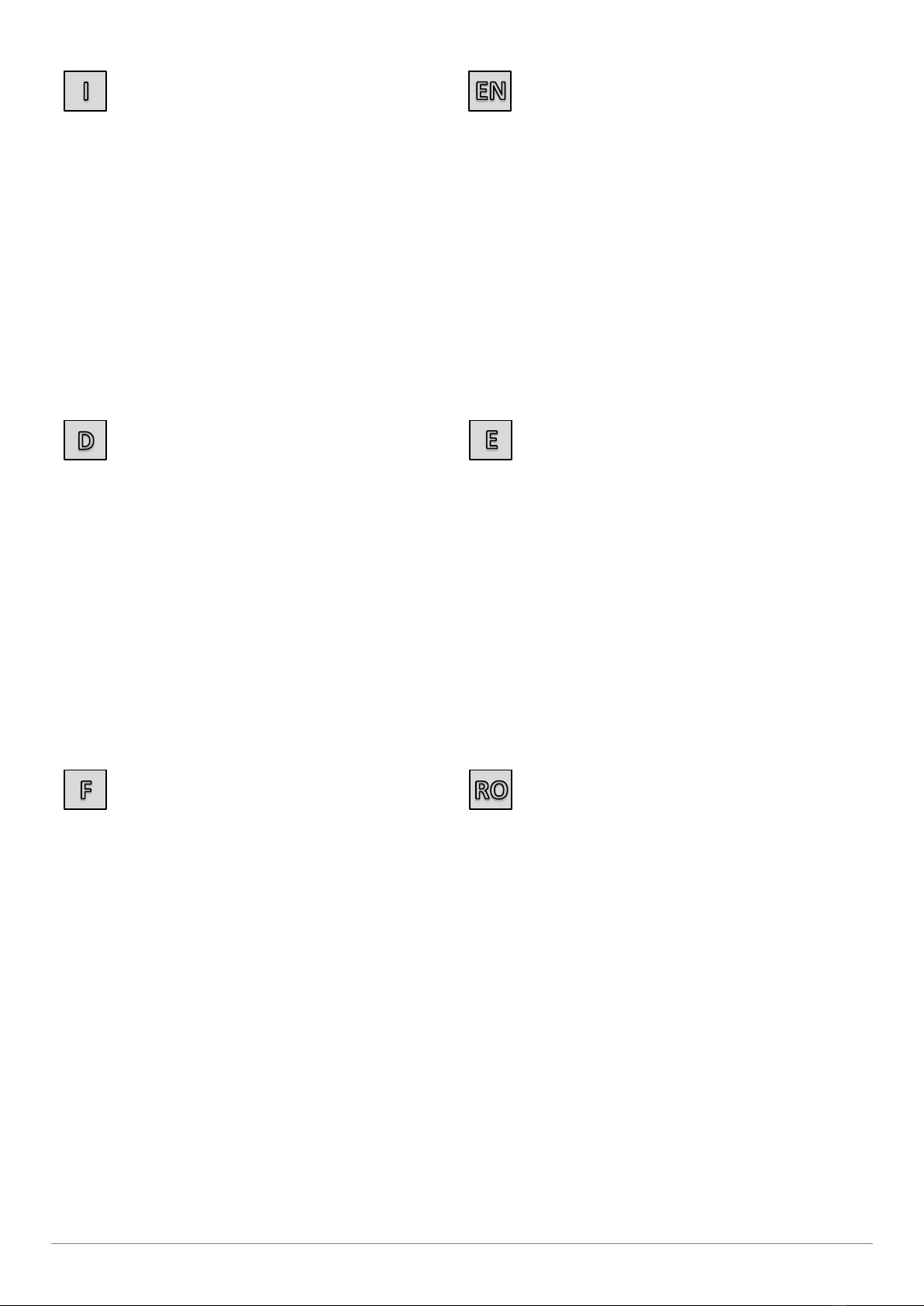
PERICOLO DI INCENDIO
Non utilizzare la macchina in atmosfera esplosiva (per la presenza di gas,
vapori infiammabili ecc.).
Tenere fuori dal raggio d’azione dell’estrusore materiali deteriorabili con
il calore o infiammabili (oli, solventi, vernici ecc.).
PERICOLO DI
NATURA ACUSTICA
Presente su:
MOTORE
Utilizzare
CUFFIE ANTIRUMORE
PERICOLO DI INTOSSICAZIONE
PERICOLO DI ESPLOSIONE
Presente su:
LASTRE/TUBI/RACCORDI
MATERIALE DI CONSUMO
Non eseguire saldature su lastre/tubi/raccordi che contengano o abbiano
contenuto sostanze che, combinate con il calore, diano origine a vapori
tossici o esplosivi.
Impiegare con accortezza le sostanze chimiche tossiche usualmente
adoperate durante le fasi di preparazione alla saldatura:
lontano da fiamme libere e superfici calde;
non fumare;
ventilare il posto di lavoro.
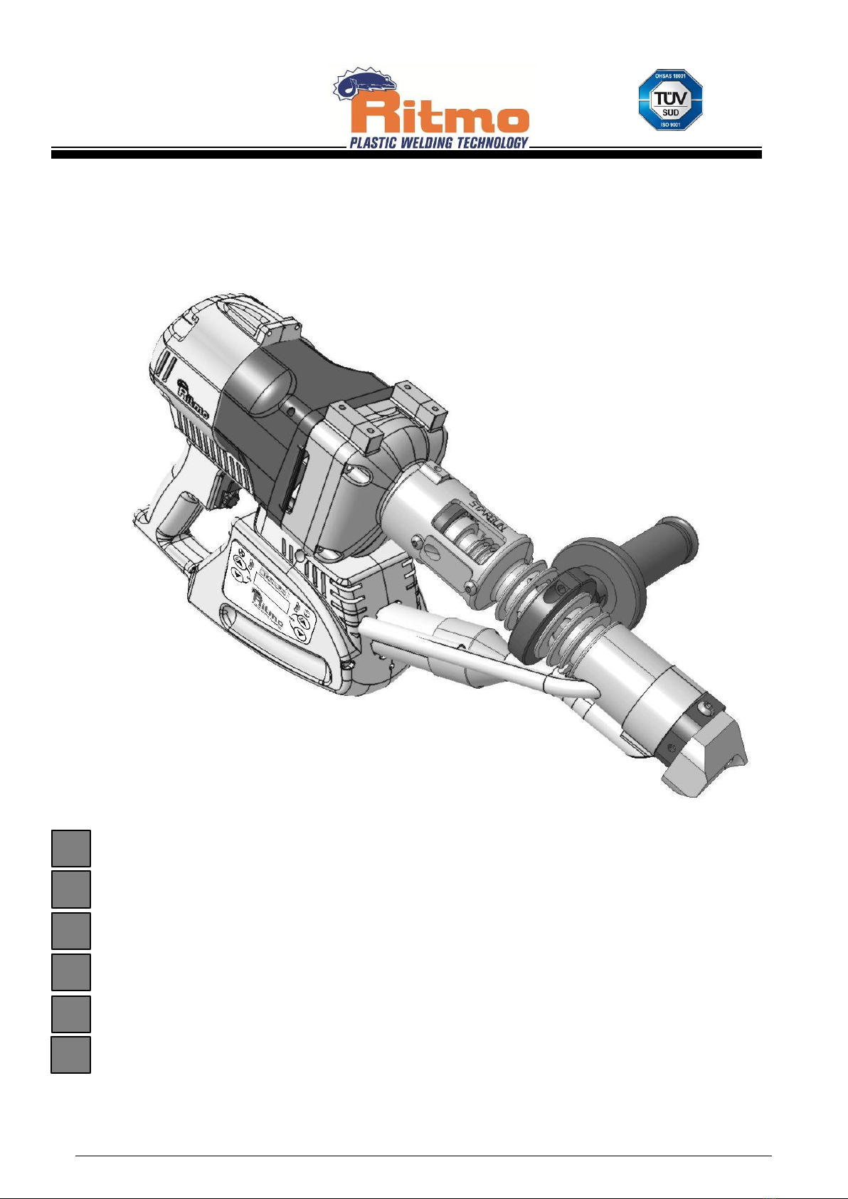
6. CRITERI GENERALI DI SALDATURA
ESTRUSORE
Per il pre-riscaldamento delle parti da saldare, vi è montato uno strumento
riscaldante ad aria calda, la quale viene alimentata autonomamente dallo
strumento stesso.
La pressione di saldatura viene data attraverso il puntale in materiale
antiaderente fissato direttamente all’estrusore e corrispondente all’uscita
del cordone di saldatura. A seconda dell’applicazione il puntale può
presentare diverse configurazioni, per garantire una corretta ed omogenea
pressione.
Il filo di apporto, fornito in bobina, necessario alla saldatura, viene inserito
nell’apposito foro per essere plastificato nel mini estrusore. A seconda del
diametro del filo inserito, si otterranno delle portate d’estrusione in Kg,
diversificate.
ESECUZIONE
Le superfici delle parti da saldare vengono riscaldate alla temperatura di
saldatura per mezzo dell’aria calda che fuoriesce dall’apposito ugello. Il
materiale d’apporto, che esce in continuo dall’apparecchio condotto
manualmente, viene pressato sui componenti da saldare. Il flusso di
materiale che esce, spinge automaticamente in avanti l’apparecchio e
definisce la velocità di saldatura. il riscaldamento delle superfici da
accoppiare dev’essere adattato alla velocità di saldatura.
REQUISITI DEI MATERIALI
Semilavorati e materiale d’apporto devono essere idonei alla saldatura per
estrusione.
Per quanto riguarda il tipo di materiale plastico, la designazione del tipo e
le caratteristiche essenziali del materiale, dovrebbe essere disponibile
almeno un certificato del produttore, conforme alla DIN 50049.
Materiali base e di apporto devono essere in perfette condizioni di
lavorazione. Accertarsi della saldabilità delle parti secondo DVS 2203.
MATERIALE DI APPORTO PER SALDATURA
Il materiale d’apporto dev’essere scelto in base alla rispettiva saldatrice ad
estrusione scelta per la lavorazione ed al tipo di materiale del semilavorato.
Il filo utilizzato come materiale d’apporto, deve rispettare determinate
caratteristiche di precisione dimensionale, della forma e di assenza di cavità
da ritiro (DVS 2211).
Non vanno lavorati dei materiali di provenienza sconosciuta. Non è
ammessa la lavorazione di materiali rigenerati.
Il filo d’apporto dev’essere asciutto e pulito; ciò significa anche che si deve
evitare la presenza di umidità sullo stesso per non rischiare di interporla nei
giunti saldati.
FORME DEL GIUNTO
Nella scelta delle forme del giunto per recipienti ed apparecchi, valgono in
generale le norme di riferimento DVS 2205.
In modo particolare vanno tenuti presenti i principi generali di
configurazione, da un punto di vista di tecnica della saldatura, qui formulati.
Nella saldatura per estrusione vengono generalmente saldati dei giunti ad
uno strato di apporto. Se, nel caso dei semilavorati più spessi, non fosse
possibile una saldatura a “Doppia V” (vedere descrizione seguente), si
possono saldare anche giunti a più strati di apporto. Il cordone deve arrivare
lateralmente circa 3 mm al di là del giunto da saldare predisposto.
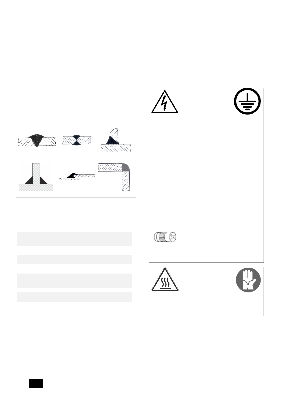
Di seguito sono rappresentate le forme dei giunti più significative e più
affermate a livello pratico per la saldatura ad estrusione.
Zona ad alta temperatura
PERICOLO DI SCOTTATURA!
PUNTALE
BOBINA
MINI
ESTRUSORE
STRUMENTO
RISCALDANTE
TRASMISSIONE

6
IT
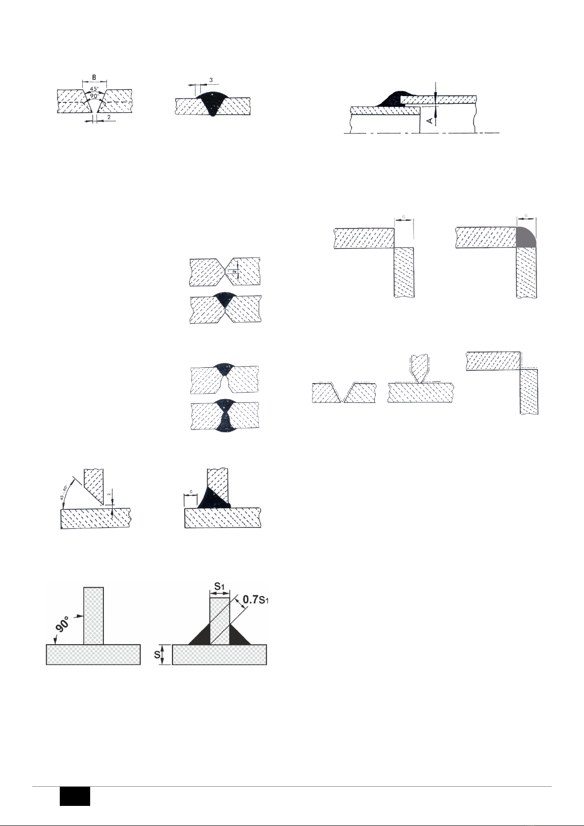
A Giunto di testa con saldatura a “v”
Giunto da saldare preparato
Giunto saldato
Va scelto un angolo di apertura tra i 45° ed i 90°, a seconda dello spessore
della lastra da saldare. La larghezza dell’apertura “B” è limitata a circa 30
mm nel caso di saldature ad uno strato di apporto, perché altrimenti il
saldatore non potrebbe più esercitare la necessaria pressione di saldatura.
Per ottenere un riscaldamento ed una saldatura sufficienti, si deve
predisporre, nella zona di vertice, una larghezza della fessura di 2 mm. Se
questa dimensione non può essere rispettata, è necessario prendere dei
provvedimenti particolari, come ad esempio dare una passata di fondo con
soffiante ad aria calda oppure ripassare con un altro strato di saldatura.
B Giunto di testa con saldatura a “Doppia V”
Preparazione lembi senza fessura
Giunto da saldare preparato
Cordone superiore saldato
Preparazione lembi con fessura
Vertice finito
Cordone inferiore saldato
Per indicazioni sulla preparazione dei lembi per la saldatura, vedere
paragrafo A.
C Giunto a “T” con saldatura ad angolo
Giunto da saldare preparato
Giunto saldato G = 10 mm
Per indicazioni sulla preparazione dei lembi per la saldatura, vedere
paragrafo A.
La sporgenza Gserve ad appoggiare e guidare il puntale di saldatura.
D Giunto “K” con doppia saldatura ad angolo
Giunto da saldare preparato
Welded joint
Per indicazioni sulla preparazione dei lembi per la saldatura, vedere
paragrafo A.
La sporgenza Gserve ad appoggiare e guidare il puntale di saldatura.
E Giunto a SOVRAPPOSIZIONE con saldatura ad angolo
Giunto saldato
Nell’esecuzione di questo tipo di giunzione, per poter riscaldare e saldare
da parte a parte in modo sufficiente, va prevista una fessura d’aria,
dipendente dallo spessore della parete e di misura non inferiore ad 1 mm
(A).
F Giunto ad angolo con saldatura esterna
Saldatura eseguibile con puntale di saldatura a richiesta
Lastre da saldare
Giunto saldato
Puntali su richiesta per diversi spessori lastra G
PREPARAZIONE DELLE SUPERFICI DA ACCOPPIARE
Zone interessate alla preparazione dei lembi
Le superfici di collegamento delle parti da accoppiare e le superfici adiacenti
alla zona dei cordoni di saldatura, vengono lavorate ad asportazione di
truciolo immediatamente prima della saldatura. Utilizzare per questo scopo,
attrezzi idonei. Le parti la cui superficie sia stata danneggiata da agenti
atmosferici o chimici, vanno consumate fino a raggiungere la zona indenne;
questa situazione si presenta soprattutto nel caso di lavori di riparazione
È’ importante non utilizzare detergenti che abbiano effetti solventi o
gonfianti sul materiale plastico
Per equilibrare eventuali differenze considerevoli di temperatura tra i pezzi
da saldare, è necessario stoccarli sul posto di lavoro, per un tempo
sufficiente a riportarli alle stesse condizioni, prima della lavorazione e
dell’esecuzione della saldatura
RIPASSATURA DEL GIUNTO SALDATO
I giunti dovrebbero per principio essere eseguiti in modo tale che non fosse
necessario un trattamento successivo.
Nel caso si esegua una ripassatura, è necessario anteriormente controllare
visivamente che la saldatura già effettuata, sia priva di difetti.
Nell’esecuzione della ripassatura, bisogna evitare gli intagli.
SICUREZZA DELLA QUALITA’ DEL GIUNTO SALDATO
Nell’esecuzione si devono raggiungere i valori di resistenza stabiliti nel
calcolo della struttura saldata. Dalla norma DVS 2205 si possono verificare i
dati sulle resistenze che si possono ottenere per i giunti saldati. Va’ tenuto
presente che i valori indicati nella norma, si riferiscono ad una saldatura ad
estrusione con sistema a “V” sul giunto di testa. Nel caso di altre forme e
tipi di giunto, è necessario prevedere dei valori di resistenza inferiori.
Le norme DVS 2203 e 2206, contengono delle indicazioni riguardanti la
prova dei giunti saldati e di strutture saldate.
Come prova accelerata, si consiglia la prova di piegatura descritta nei
paragrafi della DVS 2203.

IT
7
7. USO
PREPARAZIONE ESTRUSORE
Applicare nella parte terminale dell’estrusore, il puntale corrispondente al
tipo di saldatura da effettuare.
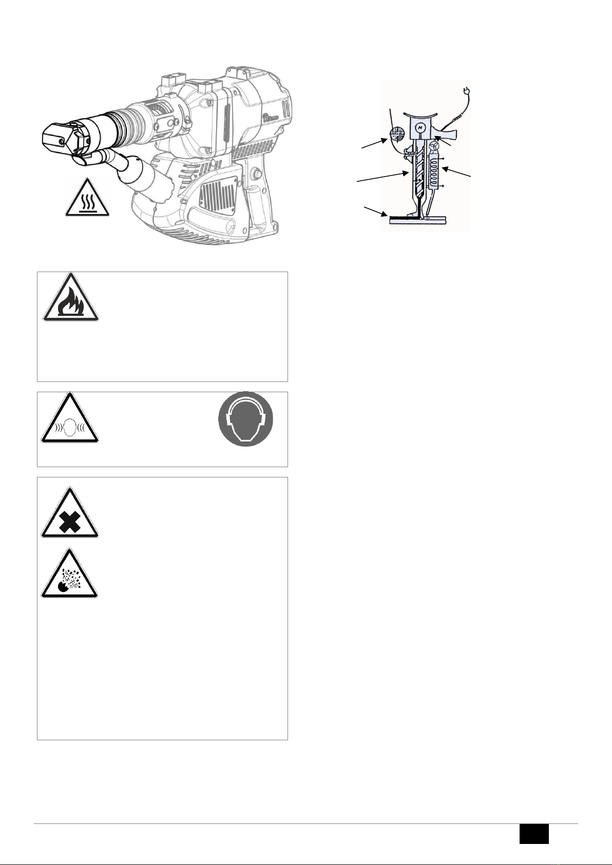
SOSTITUZIONE PATTINO
La sostituzione del puntale deve essere effettuata con la macchina alla
temperatura di esercizio.
ATTENZIONE !!!: questa operazione comporta il rischio di
ustione e deve essere portata a termine dall’operatore
esclusivamente indossando guanti anticalore di protezione.
PERICOLO DI SCOTTATURA
•Allentare le viti Fe D.
•Smontare il supporto puntale Bdalla macchina.
•Togliere il puntale Asvitando le viti C.
•Fissare il nuovo puntale Asul supporto B
•Rimontare il supporto puntale Bsulla macchina
•Avvitare completamente le viti F
•Avvitare la vite D. Se si desidera che il puntale ruoti liberamente
durante l’uso non serrare completamente la vite D.
COLLEGAMENTO ELETTRICO
Effettuare il collegamento elettrico con la linea di rete o con
generatore di corrente.
Nel caso si utilizzi un generatore, assicurarsi che abbia uno stabilizzatore di
tensione.
Nel caso si utilizzino cavi elettrici di prolunga, verificare che abbiano una
sezione adeguata alla loro lunghezza.
PROLUNGHE (230 V)
Lunghezza massima [m] 19 20 ÷ 50
Sezione cavo [mm2] 2,5 4
RISCALDAMENTO
Attendere il tempo di riscaldamento della camera di plastificazione.
Nota
Gli estrusori STARGUN LINK sono dotati di un sistema di sicurezza “blocco
motore” che agisce in questo modo:
•non permette la partenza accidentale finché non è stata raggiunta la
T° minima di scala;
•a regime se la T° impostata varia più di 10 °C, il motore si spegne fino
al raggiungimento del nuovo valore.
Trascorso il tempo di riscaldamento (READY!) l’estrusore e’ pronto all’uso.
La temperatura della camera di plastificazione e dell’aria di
preriscaldamento sono quelle impostate durante l’ultima saldatura. Per
modificare tali valori in funzione delle esigenze applicative seguire le
istruzioni seguenti.
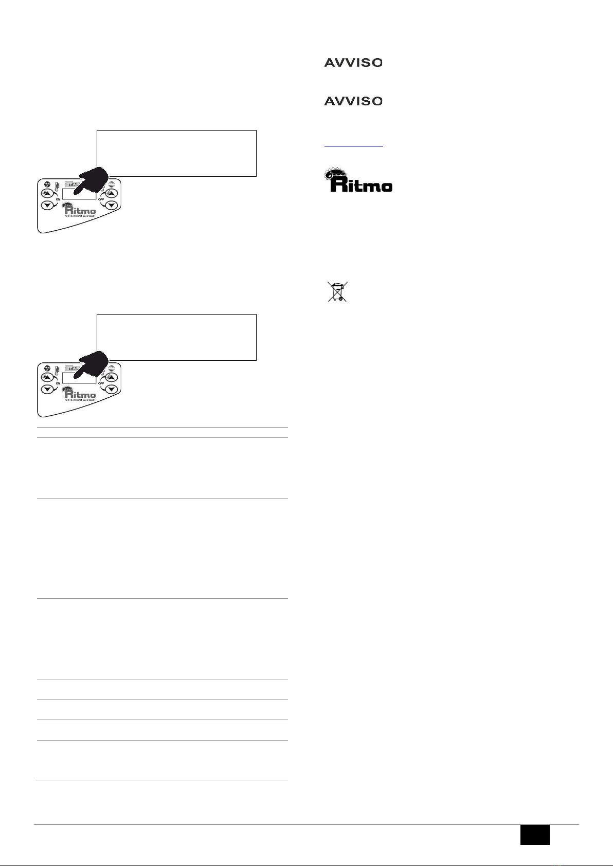
IMPOSTAZIONE TEMPERATURA ARIA
Per modificare la temperatura dell’aria di preriscaldamento tenere premuto
per circa 3 secondi il tasto 2 .
Utilizzare i tasti 2/3per modificare il valore della temperatura ( T min=250°C
–T max=365°C ). Dopo circa 5 secondi il nuovo valore viene salvato.
A
B
F
F
D
C
**STARGUN LINK**
V1.0
HEATING
PLEASE WAIT 120
READY!
278 215
CHANGE
280
3
2
8
IT
IMPOSTAZIONE TEMPERATURA ESTRUSO
Per modificare la temperatura della camera di plastificazione tenere
premuto per circa 3 secondi il tasto 7 .
Utilizzare i tasti 6/7per modificare il valore della temperatura ( T min=195°C
–T max=260°C ). Dopo circa 5 secondi il nuovo valore viene salvato.
Temperature d’utilizzo
Per le temperature di esercizio far riferimento alla norma DVS2207-4.
VERIFICHE
Prima di avviare l’estrusione assicurarsi che non ci siano tappi di materiale
freddo che ostruiscano l’orifizio d’uscita dell’estruso. Se necessario,
rimuovere delicatamente con una punta di cacciavite, quando il materiale
plastico è ancora morbido.
Attenzione! Utilizzare occhiali di sicurezza durante le
operazioni. Non porsi mai di fronte all’ ugello di uscita dell’
estruso!
premere il pulsante di avvio motore Ped il pulsante di blocco Bper avviare
l’estrusione.
Contemporaneamente inserire il filo di apporto nell’apposito foro. Far
uscire per circa 10 sec il materiale dal puntale ed accertarsi che sia
plastificato correttamente, dopodiché procedere alla saldatura.
Verificare una corretta plastificazione del materiale
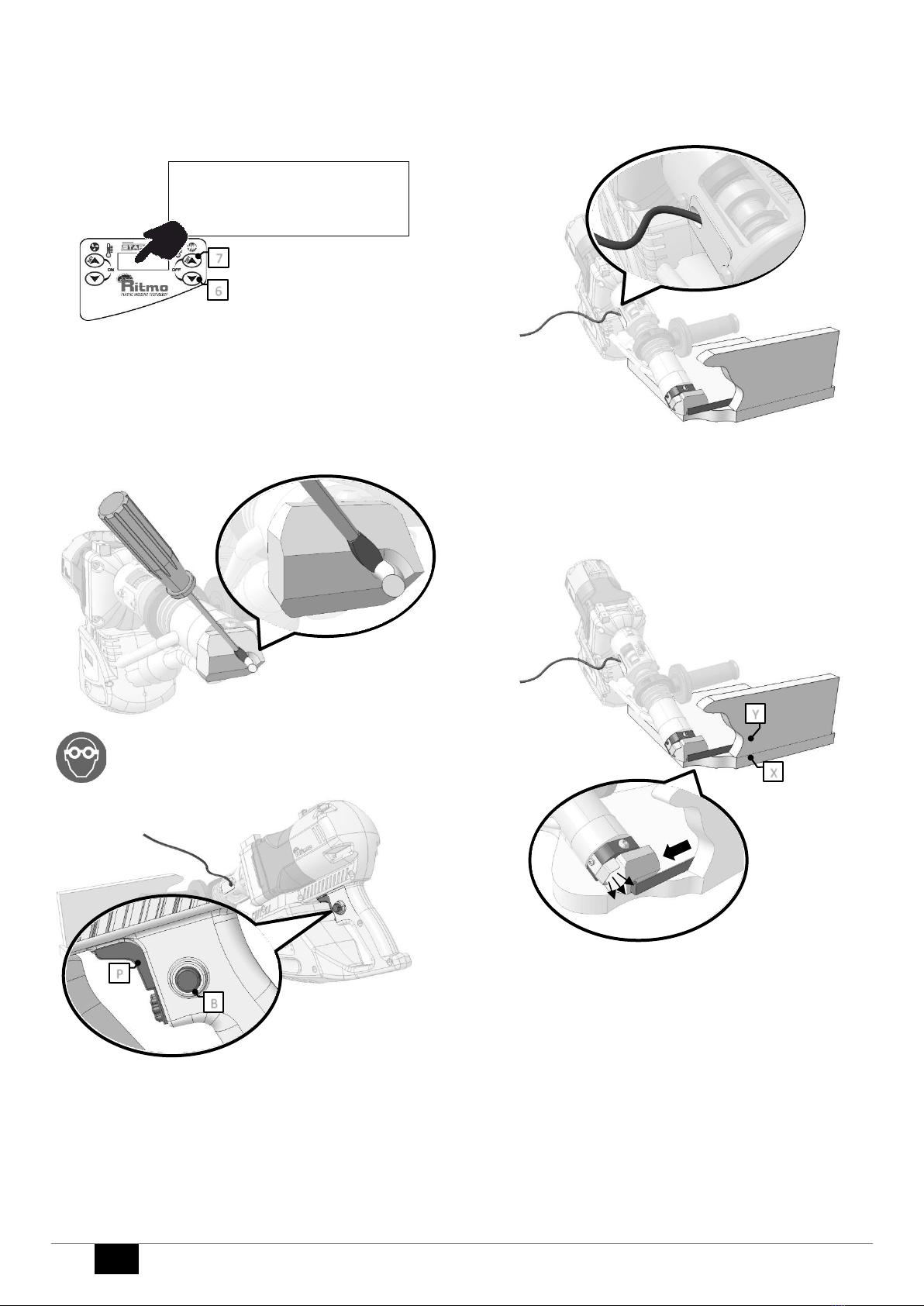
ISTRUZIONI OPERATIVE
•Appoggiare il puntale sui due supporti da saldare (esempio X e Y).
Preriscaldare la zona di saldatura per alcuni secondi prima di avviare
l’estrusione.
•Esercitando una certa pressione, accompagnare l’avanzamento
dell’estrusore.
•Seguire il verso di saldatura come indicato dalla freccia nella figura. Il
soffio di aria calda per il preriscaldamento del materiale deve sempre
precedere l’apporto del materiale estruso. Uno scorretto
preriscaldamento non garantisce la compenetrazione del materiale
d’apporto con i supporti da saldare(“effetto incollaggio”).
Attenzione! Evitare che il materiale estruso vada ad invadere la zona
preriscaldata ostruendo il condotto dell’aria calda.
CHANGE
220
6
7
B
P
Filo di
apporto
X
Y

IT
9
Attenzione! Non lasciare che alcun filo elettrico entri in contatto
diretto con l’ estruso!
GEOMEMBRANE
Se il materiale da saldare è particolarmente sottile, può essere utile limitare
l’uso della soffiante. A questo scopo diminuire la temperatura della
soffiante sotto i 225°C.
Il display mostrerà temperatura soffiante = 225°C/OFF (intermittente)
e la portata dell’aria diminuirà fino al minimo.
A fine saldatura riporre l’estrusore sull’apposito appoggio.
SPEGNIMENTO
Premendo contemporaneamente i tasti 6/7 la macchina provvederà alla
procedura di spegnimento. Il soffiante continuerà ad erogare un flusso
d’aria per circa due minuti necessario al raffreddamento della resistenza
elettrica.
Attenzione! : La procedura di spegnimento non prevede il completo
raffreddamento delle varie parti calde della macchina ma serve solo ad
abbassare la temperatura della resistenza elettrica per garantirne una
durata superiore. Per evitare scottature accidentali attendere il naturale
raffreddamento delle parti.
Terminato il tempo di raffreddamento comparirà sul visualizzatore la scritta
OFF.
Se si desidera accendere nuovamente la macchina premere
contemporaneamente i tasti 2/3, altrimenti scollegare la macchina dalla
fonte di alimentazione.
Attenzione! Staccare sempre l’alimentazione al termine delle operazioni.
MENÙ IMPOSTAZIONI GENERALI
Per entrare nel menù impostazioni generali, mantenere premuto il tasto 2
entro 6 secondi dal collegamento della macchina alla fonte di alimentazione.
Se entro 6 secondi non si riesce ad accedere al menù, bisognerà scollegare
la macchina dalla fonte di alimentazione, ricollegarla e procedere come
sopra descritto.
Premere i tasti 6/7per selezionare il menu desiderato.
Premere il tasto 3per accedere al menù.
NUMBER 0 : visualizza le ore totali di lavoro della macchina (ht) e il tempo
parziale (..h: ..m)
NUMBER 1 : premendo il tasto 3consente di azzerare il tempo parziale di
lavoro (0h:0m)
Il conta-ore si aggiorna ogni 4,5 minuti di estrusione.
NUMBER 2 : consente di determinare l’unità di misura della temperatura.
Agire sui tasti 6/7per selezionare celsius CEL o fahrenheit FAR.
Premere nuovamente il tasto 3per uscire salvando i dati impostati.
READY!
225 [OFF] 215
3
2
COOLING
Please wait 97 sec
6
7
OFF
3
2
HEATING
PLEASE WAIT 120
2
NUMBER?
0
6
7
3
XXH YYH ZZM
ore totali di
estrusione
tempo parziale di
estrusione

10
IT
REGOLAZIONE FLUSSO ARIA
Impostare menu 45 e premere il tasto 3.
Usare i tasti 6 e 7 per cambiare la velocità della soffiante.
Premere il tasto 3 per confermare
8. MANUTENZIONE
Attenzione
•Sconnettere la macchina dalla rete elettrica prima di eseguire qualsiasi
intervento di manutenzione.
•Far eseguire le operazioni di manutenzione da personale specializzato.
Prima di ogni intervento, attendere il raffreddamento completo
dell’estrusore.
PULIZIA DELL’ INDOTTO
Pulire l’ indotto ad ogni cambio spazzole con materiale abrasivo adeguato.
PULIZIA DEI FILTRI ARIA
Pulire periodicamente con pistola ad aria compressa la scatola elettrica in
corrispondenza delle feritoie per l’aria.
Attenzione
Non usare detergenti corrosivi
Quando necessita rimuovere residui ostinati, fare attenzione a non
danneggiare i cavi di connessione.
Pulire il display del termoregolatore con un panno morbido.
NUMBER?
45
6
7
3
X 1000: 23/18
▊▊▊▊▊▊▊▊▊
6
7
3
IT
11
9. MALFUNZIONAMENTI
Il sistema è fornito di una diagnostica automatica allo startup.
Se dovessero comparire errori, come nell’esempio sottostante, ripristinare
il sistema staccando la spina.
Se l’errore dovesse persistere, contattare un centro di assistenza
autorizzato. Esempio di errore nella diagnostica di startup:
Una volta concluso il sistema diagnostico iniziale, un nuovo sistema
diagnostico viene attivato.
Il sistema diagnostico potrebbe bloccare l’estrusore visualizzando
schermate simili alla seguente:
Error
Descrizione degli Errori (Err)
5
Nessuna risposta dalla lettura delle sonde di temperatura
Causa probabile:
Errore hardware della scheda elettronica
Contattare un centro di assistenza autorizzato
10
La temperatura della camera di plastificazione non puo’ essere
stabilizzata
Causa probabile:
a. Cambio repentino delle condizioni di lavoro (es. troppa
estrusione o troppo poca)
b. Errore della sonda di temperatura
Riaccendere l’estrusore
Se l’errore persiste, contattare un centro di assistenza autorizzato
15
La temperatura dell’aria soffiante non puo’ essere stabilizzata
Causa probabile:
a. Cambio repentino delle condizioni di lavoro (es. L’uscita
dell’aria e’ ostruita)
b. Temperature probe fault.
Riaccendere l’estrusore
Se l’errore persiste, contattare un centro di assistenza autorizzato
20
La temperatura della camera di plastificazione e’ troppo alta
Contattare un centro di assistenza autorizzato
25
La temperatura dell’aria della soffiante e’ troppo alta
Contattare un centro di assistenza autorizzato
30
Controllo soffiante non attivo
Contattare un centro di assistenza autorizzato
35
Temperatura elevate nella scatola elettronica
(sopra 95°C/200F)
Fare attenzione alle condizioni ambientali. Assicurarsi che i filtri non
siano intasati.
Le caratteristiche tecniche della macchina e i dati inclusi in questo manuale
possono essere modificati senza preavviso, su decisione del produttore.
È' vietata la riproduzione anche parziale di questo
manuale
Ricambi e documentazione tecnica sono disponibili anche online:
www.ritmo.cloud
Assistenza in caso di problemi:
S.p.A.
via A. Volta, 35/37 - Z.I. Selve
35037 BRESSEO DI TEOLO (PD)
ITALY
Tel. +39.049.990.1888
Fax +39.049.990.1993
service@ritmo.it
SMALTIMENTO
Non gettare nei rifiuti domestici! Porta il dispositivo inutilizzabile in
una raccolta separata per il riciclaggio ecologico.
CHK 4
C:0 R:0
ERR: 0
12
EN
Dear Customer,
Thank you for choosing a extruder from the Ritmo range of products.
This manual is designed to illustrate the features and operating methods of
your new extruder welder model STARGUN LINK. It contains all the
necessary information and prescriptions for correct and safe use of the
equipment by professional operators. Please read all parts of the manual
carefully and keep it in a
safe place for future consultation and/or to transfer to any future
owners/users of the extruder. We are confident that you will enjoy getting
to know your new equipment and will be able to use it profitably for many
years to come.
1. FIELD OF APPLICATION
The STARGUN LINK is a mini portable extruder adapt to the welding by
extrusion of plastic material such as Polyethylene
(PE), Polypropylene (PP).
Examples of weldings
“V”
“DV”
90°
D_ K
Film Overlay
External Angle
2. TECHNICAL FEATURES
LINK 20
LINK 30
LINK 40
Rod Diameter
1/8 –5/32
inch
3 –4 mm
1/8 –5/32 –
3/16 inch
3 –4 –5 mm
5/32 –3/16
inch
4 –5 mm
Max Extrusion
Output
5 lbs/h
2.2 Kg/h
7 lbs/h
3.2 Kg/h
9 lbs/h
4 Kg/h
Weldable
material
PE, PP, PVDF
PE, PP, PVDF
PE, PP
Rated Voltage
230V50Hz
230V50Hz
110V60Hz
230V50Hz
Rated Power
[KW]
3.1 KW
3.2 KW 230
V
2.7 KW 110V
3.7 KW
Noise
LwA = 78 dBA
Weight
14.5 lbs
6.5 Kg
15 lbs
6.8 Kg
16 lbs
7.3 Kg
3. DIMENSIONS
on page 52
4. PARTS
on page 52
5. SAFETY CRITERIA
The use of STARGUN LINK is reserved exclusively for trained and suitably
skilled personnel in accordance with the regulations in force.
Use the extruder exclusively for the purpose described in section Field of
application” and in accordance with the operating and maintenance
instructions. Any other type of utilization is considered as improper use and
therefore prohibited because of the risk of serious injury of operators, other
persons and/or damage to the extruder and other property.
Immediately replace all worn or damaged parts using exclusively Ritmo
original spare parts.
All repairs on the extruder must be performed by skilled and qualified
personnel.
Context:
MOTOR & BLOWER
SHOCKING
HAZARD
CHECK GROUND
CONNECTION
Check that the electrical characteristics of the extruder correspond to
the specifications of the power supply line.
During connection phase between electrical board and electrical line,
verify the presence of safety differential and magneto-thermal devices
on electrical supply line.
If necessary, proceed with calibration. Inlets on electrical board must be
of type IEC 309 with minimum protection grade IP44. Do not expose the
extruder to rain or other liquids.
Make sure that isolating protections (for example gloves) are always
perfectly dry.
Do not expose electrical wiring or hydraulic hoses to chemical
substances or mechanical stress (e.g. pedestrian or vehicular traffic,
contact with sharp objects, pulling, etc.).
Disconnect the power socket outlet from the electrical power supply
when work with the extruder has been concluded or temporarily
suspended. Before using the extruder check the condition of individual
electrical system components, particularly insulating parts, cables, cable
glands and cable jaws.
Clean the extruder thoroughly after each session. Avoid the use of
solvent, petrol and abrasive substances which could damage insulated
parts of the extruder.
Connection cable must agree to regulation and
required power.
Connection must be done with plug IEC 309, IP67.
20 A 230-250V.
Small or humid places, building sites surrounded by metallic masses or
water (for example shipyards) require use of equipment fed in SELV
(very low safety tensions).
Context:
BLOWER, MELTING
CHAMBER AND
WELDING SHOE
RISK OF BURNING
USE
PROTECTION
GLOVES
Handle the extruder carefully.
Do not touch welding bead and near areas before complete cooling.

EN
13
Context: MOTOR AND BLOWER
FIRE HAZARD
Do not use the extruder in presence of explosive gases and vapors.
Keep away from extruder materials that can deteriorate with heat
inflammable (oil, solvents, etc.).
NIOSE EXPOSURE
Context:
MOTOR
WEAR EARMUFFS
CHEMICAL HAZARDS
RISK OF EXPLOSION
Context:
SHEETS/PIPES/FITTINGS
OTHER FABRICATION
MATERIALS
Do not weld sheets, pipes or fittings that contain or have previously
contained toxic substances.
Use carefully those chemical substances used during preparations before
welding:
Stay away from flames or hot surfaces;
Do not smoke;
Ventilate the work place.
6. WELDING CRITERIA
EXTRUDER
Portable welding extruder is composed by a mini extruder with a plasticizing
unit, operated by an electric MOTOR.
The pre-heating of parts to weld is done with a hot air blower, where the air
is generated independently by the blower.
Welding pressure is given with the no-stick welding shoe directly assembled
on the extruder and corresponding to the outlet of welding rod. According
to the application welding shoe can have different configurations, to
guarantee a correct and homogeneous pressure.
Welding material, supplied in coils, necessary for welding, is positioned in
the special hole to be plasticized in the same extruder. According to
diameter of rod, different quantities of material in Kg will be extruded.
WELDING PRINCIPLES
Surfaces of parts to be welded are heated at welding temperature by hot
air which comes out from special nozzle. Welding material, continuously
coming out from the welder manually operated, is pressed on components
to be welded. Flux of material, pushes forward automatically the apparatus
and determine welding speed. The heating of surfaces to be welded
together must be adapted to welding speed.
MATERIAL REQUIREMENTS
Welding material and material to be welded must be suitable for extrusion
welding.
As far as plastic material, for type and main characteristics of material, a
certificate of the producer should be available, according to DIN 50049.
Welding material and parts to be welded must be in perfect conditions.
Make sure they can be welded according to DVS 2203.
WELDING MATERIALS
Welding material must be chosen according to extruder welder chosen for
the work and kind of material to be welded. Rod used as welding material,
must follow certain characteristics of dimensional precision, of form and
absence of contraction cavities (see Bulletin DVS 2211).
Material of unknown origins should not be welded. Welding of recycled
materials is forbidden.
Welding rod must be dry and clean; also avoid humidity for not risking to
waste the weld.
WELDING GEOMETRY
When choosing welding geometry for containers or other apparatus, refer
to regulations DVS 2205.
In particular general principles of configuration must be taken into
consideration, from a welding technique point of view, as follows.
In the extrusion welding are generally welded joints with only one deposit
of plastic . If in case of very thick materials, “Double V” weld would not be
possible to perform (see following description), it is possible to weld joints
with several welding layers. Welding rod must go about 3 mm beyond joint
to be welded.
Following are the most used and known types of extrusion welds.
HOT
BURNING AREA
SHOE
WELDING ROD
MINI
EXTRUDER
HEATING COIL
TRANSMISSION
14
EN
A “V”weld
Separate joint to be welded
Welded joint
An angle between 45° and 90° must be chosen, according to sheet to be
welded. Width of opening “B” is limited to about 30 mm in case of welds
with only one welding layer, otherwise the operator would not be able to
perform the necessary welding pressure.
To obtain a good heating and welding, it is necessary to prepare, on top part,
a fissure 2 mm wide. If this dimension cannot be respected, it is necessary
to do something, like for example use some more hot air or make another
layer of weld.
B Double “V” weld
Preparation of edges without fissure
Joint to be welded
Welded top part
Preparation of edges with fissure
Top part welded
Down part welded
For instructions on preparation of the edges before welding, see section A.
C “T” joint with corner weld
Joint to be welded
Welded joint G = 10 mm
For instructions on preparation of edges before welding, see section A.
Projecting part G is to lay down and drive welding shoe.
D K-weld
Joint to be welded
Schweißnaht
For instructions on preparation of edges before welding, see section A.
Projecting part G is to lay down and drive welding shoe.
E Overlapping Joint
Welded joint
When performing this kind of weld, in order to be able to heat and weld
properly from one part to the other, it is necessary to leave a little fissure,
which depends from thickness of the sheet and not smaller than 1 mm (A).
F External corner weld
Teflon shoe on demand is required
Joint to be welded G
Joint
Teflon shoes available for G-thickness
PREPARATION OF SURFACES TO BE WELDED
Areas interested in the preparation of the edges
Surfaces which are going to be welded and surfaces near the area of welding
string, are treated and scraped just before welding. For this purpose, only
use suitable tools. Parts which surfaces have been damaged by atmospheric
or chemical agents, must be scraped until reaching the intact zone; this
situation often occurs when repairing something It is important to avoid
using solvent detergents or detergents that might deform the material.
In order to re-equilibrate possible differences in temperature between
materials to be welded, it is necessary to stock them in working place, for a
period of time necessary for them to become of same characteristics,
before performing any welding
GOING OVER THE JOINT AGAIN
Welds should be done in such a way that do not need any further
treatments.
In case one wants to go over the weld again, it is necessary to make sure
that the previous weld is without any imperfection. When going over the
weld again, it is necessary to avoid notches.
SAFETY AND QUALITY OF THE JOINT
When making a joint, it is necessary to reach value of resistance fixed in the
calculation of the welded material.
From DVS 2205 regulation it is possible to verify data on the resistance that
can be obtained on the welded joints.
It is necessary to consider that the values shown in the regulation, are
referred to a “V” weld. In case of other types of welds, it is necessary to
consider lower resistance.
Regulations DVS 2203 and 2206, describe indication about tests on the
welded joint and welded structures.
A fast test would be the folding which is described on the DVS 2203.

EN
15
7. USE
SETUP
Insert the shoe most suitable to the welding to carry out around the
extrudate hose.
SHOE REPLACEMENT
It must be carried out when the extruder is still hot.
WARNING!!!: this operation involves the risk of burns and
must be completed by the operator only wearing heat-
resistant protective gloves.
BURN HAZARD
•Lose screws Fand D.
•Take off the shoe support B.
•Unscrew Cand remove shoe A.
•Mount a new shoe Aon support B.
•Mount again Bon the extrudate hose.
•Tighten screws F
•Tighten Dto fix the shoe position or keep it lose to let it turn around
the extrudate hose.
MAINS CONNECTION
Plug into the mains. Power generators require a voltage stabilizer.
Extensions require the minimum cable sections below.
EXTENSIONS (230 V)
Max length [m] 19 20 ÷ 50
Cable section [mm2] 2,5 4
WARM UP
Wait for the extruder to warm up.
Note
The extruder is equipped with a safety system that disables the motor if:
•the minimum working temperature has not been reached;
•a new set point, that is greater or lower than 10°C, has been typed in.
Once the heating time has been elapsed (READY!), the hand extruder is
ready to start.
The temperature of the air and the extrudate chamber are those stored
since the last usage.
AIR TEMPERATURE SETTING
Hold button 2pressed for 3 sec. Use buttons 2and 3to set the air
temperature within the range T min=250°C –T max=365°C. The new setting
point is stored after 5 sec.
A
B
F
F
D
C
**STARGUN LINK**
V1.0
HEATING
PLEASE WAIT 120
READY!
278 215
CHANGE
280
3
2

16
EN
EXTRUDATE TEMPERATURE SETTING
Hold button 7pressed for 3 sec. Use buttons 6and 7to set the air
temperature within the range T min=195°C –T max=260°C. The new setting
point is stored after 5 sec.
Working temperature
Please refer to standard DVS 2207-4.
CHECKS
Make sure the extrudate-hose is not clogged before triggering the motor.
If necessary, gently remove the extrudate clogging when it’s turning soft
with a flat screwdriver tip.
WARNING! Use eyewear. Do not stand in front of the extrudate hose.
Pull the motor trigger Pand button Bto start the extruder.
Simultaneously insert the filler wire into the appropriate hole. Leave the
extrudate to come out of the tip hose for about 10 seconds and make sure
that it is plasticized correctly, then proceed with welding.
Make sure the extrudate is flowing smoothly.
OPERATING INSTRUCTIONS
• Place the shoe on the two sheets to be welded (example X and Y). Preheat
the welding area for a few seconds before starting the extrusion.
• Apply some pressure while moving the extruder.
• Follow the welding direction as indicated by the arrow in the figure. The
blowing of hot air for the preheating of the material must always precede
the supply of the extruded material. An incorrect preheating does not
guarantee the interpenetration of the filler material with the sheets to be
welded ("gluing effect").
Warning! Prevent the extruded material from invading the preheated area
and blocking the hot air duct.
CHANGE
220
6
7
B
P
Filler wire
X
Y

EN
17
WARNING! Do not let any electrical wire come into direct
contact with neither the extruded nor the hot surfaces!
LINERS –GEOTEXTILES
If the sheets to be welded are very thin, it is possible to decrease the blower
flow.
Decrease the air temperature below 225°C: the display will show a flashing
‘225°C/OFF’ while air flow slows down.
At the end of welding, place the extruder on the appropriate support.
SHUTDOWN
Push buttons 6and 7together: the air temperature decreases to cool down
the heating resistors, while a countdown starts on the display.
CAUTION! The shutdown procedure does not provide for the complete
cooling of the various hot parts of the extruder but only serves to lower the
temperature of the heating resistors to ensure a longer duration. To avoid
accidental burns, wait for the parts to cool naturally.
Once the cooling countdown is over, the display shows ‘OFF’.
Push together buttons 2 and 3to turn on the extruder again or unplug it.
WARNING! Always unplug the extruder at the end of working day.
SETTINGS MENU
Hold down button 2 within 6 seconds from connecting the extruder to the
power source to enter the settings menu.
If within 6 seconds you cannot access the menu, disconnect the extruder
from the power source, reconnect it and proceed as described above.
Push buttons 6 and 7 to select the menu number to access. Push button 3
to confirm.
Number 0: it displays the MOTOR working hours (..h: ..m) with partial and
total time counter.
Number 1: press button 3to zero the partial time counter above.
Note: The partial counter registers each sec of MOTOR in use and updates
the display value for each 4 1/2 min of use.
Number 2: use to switch between Celsius and Fahrenheit. Use buttons 6
and 7to select Celsius CEL or Fahrenheit FAR.
Press button 3to save the settings.
WARNING! The advanced menus (from 3 on) are for factory settings only
READY!
225 [OFF] 215
3
2
COOLING
Please wait 97 sec
6
7
OFF
3
2
HEATING
PLEASE WAIT 120
2
NUMBER?
0
6
7
3
XXH YYH ZZM
Total working hours
Partial working hours

18
EN
AIR-FLOW SETTING
Set 45 push button 3 to confirm.
Use buttons 6 and 7 to set the air flow.
Push button 3 to confirm.
8. MAINTENANCE
Warning
•Disconnect extruder from electrical line before performing any
maintenance intervention.
Let specialized technicians to perform maintenance on the welder.
•Before any intervention, waitfor the complete cooling of the extruder.
COMMUTATOR/BRUSH SEATER CLEANING
Use a brush seater stone to clean the commutator. Repeat procedure at
least once per brush replacement.
AIR FILTER CLEANING
Periodically clean the air grilles with a compressed air gun.
Warning
Do not use corrosive detergents
We recommend to clean the STARGUN LINK after every use.
NUMBER?
45
6
7
3
X 1000: 23/18
▊▊▊▊▊▊▊▊▊
6
7
3

EN
19
9. TROUBLESHOOTING
The system is equipped with a self-diagnostic of the hardware at the startup.
If any error shows up, unplug the extruder and restart. If the error persists,
contact an authorized service center.
Example of startup diagnostic error:
Once the start-up check is over, a new self-diagnostic system is initialized
The display may show at any time the following:
Err description
#
Err description
5
No feedback from the temperature sensors.
Probable cause:
temperature controller fault.
Contact an authorized service center
10
Cannot stabilize the melting chamber temperature.
Probable causes:
a. Sudden change of working conditions (e.g. too much or too
low output)
b. Temperature probe fault.
Turn off/on the extruder.
If the error persists, contact an authorized service center
15
Cannot stabilize the blower air temperature
Probable causes:
a. Sudden change of working conditions (e.g. the blower hose is
clogged)
b. Temperature probe fault.
Turn off/on the extruder and make sure that the air flow is not
clogged.
If the error persists, contact an authorized service center
20
The melting chamber temperature is too high
contact an authorized service center
25
The blower air temperature is too high
contact an authorized service center
30
Cannot control the blower
contact an authorized service center
35
The wiring bow temperature is too high (above 95°C/200F)
Make sure that the environmental conditions are suitable to the
extruder (e.g. avoid direct sunlight, etc..)
The specifications of the device and the data entered in
this manual are subject to change without notice from the manufacturer.
Reproduction of this manual, including in part, is
prohibited.
Full parts lists and technical documents are available online at
www.ritmo.cloud.
Help in the event of problems:
S.p.A.
via A. Volta, 35/37 - Z.I. Selve
35037 BRESSEO DI TEOLO (PD)
ITALY
Tel. +39.049.990.1888
Fax +39.049.990.1993
service@ritmo.it
DISPOSAL
Do not dispose of in the household trash. Add the device that is no
longer able to be used to a separate collection for the purpose of
environmentally friendly recycling.
Contact Ritmo S.p.A. for further info.
CHK 4
C:0 R:0
ERR: 0

20
D
Sehr geehrter Kunde,
herzlichen Dank dafür, dass Sie sich für ein Gerät der Marke Ritmo
entschlossen haben.
Dieses Handbuch wurde verfasst, um die Eigenschaften und
Verwendungsweisen des von Ihnen erworbenen STARGUN LINK zu
erläutern. Im Handbuch finden Sie alle Informationen und Hinweise, die für
einen angemessenen und sicheren Gebrauch der Einrichtung durch
professionelles Bedienungspersonal notwendig
sind. Bitte lesen Sie das Handbuch in allen seinen Teilen durch, bevor Sie die
Maschine betätigen und bewahren Sie es für ein zukünftiges Nachschlagen
bzw. für eventuelle weitere Verwender auf.
Wir hoffen, dass Sie sich mit Ihrer neuen Ausrüstung rasch anfreunden
werden und sie über lange Zeit mit größter Zufriedenheit nutzen können.
1. ANWENDUNGSBEREICH
Der STARGUN LINK ist ein Handextruder für Schweißungen mit
thermoplastischem Material, wie Polyethylen (PE) und Polypropylen (PP).
V-Naht
X-Naht
HV-Naht
D_ K-Nähte
Überlappend
Ecke außen
2. TECHNISCHE EIGENSCHAFTEN
LINK 20
LINK 30
LINK 40
Schweißdraht
3 –4 mm
3 –4 –5 mm
4 –5 mm
Ausstoßleistung
2,2 Kg/h
3,2 Kg/h
4 Kg/h
Schweißbares
Material
PE, PP, PVDF
PE, PP, PVDF
PE, PP
Leistung
230V50Hz
230V50Hz
110V60Hz
230V50Hz
Maximale
Leistungsaufnahme
3,1 KW
3,2 KW 230 V
2,7 KW 110V
3,7 KW
Schallleistungspegel
LwA = 78 dBA
Gesamtgewicht
6,5 Kg
6,8 Kg
7,3 Kg
3. ABMESSUNGEN
Seite 52
4. BESCHREIBUNG DER BAUTEILE
Seite 52
5. SICHERHEITSKRITERIEN
Die Benutzung der STARGUN LINK Handextruder ist ausschließlich für
geschultes und qualifiziertes Personal vorgesehen.
Verwenden Sie die Maschine ausschließlich für die im “Anwendungsbereich”
beschriebene Funktion und unter Beachtung der Bedienungs- und
Wartungsanweisungen. Alle anderen Verwendungsweisen sind als
Zweckentfremdung und untersagt anzusehen, da sie zu Verletzungen der
Bediener oder Dritter und/oder zu Beschädigungen der Maschine oder
anderer Gegenstände führen können.
Ersetzen Sie alle abgenutzten oder beschädigten Bauteile umgehend durch
Originalersatzteile von Ritmo.
Alle Eingriffe zur Reparatur der Maschine müssen von qualifiziertem
Fachpersonal vorgenommen werden.
Vorhanden an:
Motor und Gebläse
STROMSCHLAG-
GEFAHR
ERDUNG
(Überprüfen Sie die
Wirksamkeit der
Erdung)
Stellen Sie sicher, dass die elektrischen Eigenschaften der Maschine
denen der Stromversorgungsquelle entsprechen.
Die Baustellenschalttafel oder der Stromgenerator, an die die Maschine
angeschlossen wird, müssen einen Differentialschalter mit hoher
Empfindlichkeit (I = 30 mA) aufweisen.
Die Steckdosen der Schalttafel müssen dem Typ IEC 309 entsprechen
und einen Schutzgrad von mindestens IP44 aufweisen.
Setzen Sie die Maschine nicht dem Regen oder anderen Flüssigkeiten
aus.
Stellen Sie sicher, dass die Schutzisolierungen (zum Beispiel die
Handschuhe) immer vollkommen trocken sind.
Setzen Sie die Kabel keinen Chemikalien oder mechanischen
Belastungen (wie der Befahrung oder Begehung, Kontakt mit
schneidenden Gegenständen usw.).
Trennen Sie die Steckdose bei Beendigung oder Unterbrechung der
Arbeiten von der Stromversorgung.
Stellen Sie vor der Benutzung der Maschine sicher, dass die einzelnen
Komponenten keine Beschädigungen aufweisen, vor allem die
Isolierungen, die Kabel und die Kabeldurchführungen.
Nehmen Sie nach der Benutzung eine sorgfältige Reinigung der
Maschine vor. Verwenden Sie dazu keine Lösungsmittel, Benzin oder
scheuernde Substanzen, die die Isolierungen beschädigen könnten.
Eventuelle Verlängerungskabel müssen der Norm
sowie der geforderten
Leistung angemessen sein. Der Anschluss muss
über einen Netzstecker vom Typ IEC 309 mit
Schutzgrad IP67 erfolgen.
Enge oder besonders feuchte Räume und Baustellen, die von
metallischen Massen umgeben sind (zum Beispiel Werften) machen den
Einsatz von Geräten mit SELV-Speisung (sehr niedrige
Sicherheitsspannung) erforderlich.
Vorhanden an:
Gebläse,
Plastifizierungskammer
und Schweißschuh
VERBRENNUNGS
GEFAHR
SCHUTZHANDSCHUHE
TRAGEN
Bewegen Sie den Extruder mit Vorsicht.
Berühren Sie die Schweißnaht nicht bevor das Material vollständig
abgekühlt ist.
Table of contents
Languages:
Other Ritmo Welding System manuals


