Thomas SAR 460 SA G DIGIT User manual

1
SAR 460 SA G
THOMAS S.p.A. - Via Pasubio, 32 - 36033 Isola Vicentina (VI) - Telefono 0444 / 97.61.05 - Fax 0444 / 97.69.34
Registro Imprese n. 4272//VI 116 REA n. 93906/Vicenza
SAR460SAG
DIGIT
USE AND MAINTENANCE MANUAL
2005/SRT

2
SAR460SAG
Contents
Contents ........................................................................ " 2
Ordering spare parts .................................................... " 2
Guarantee ...................................................................... " 2
Machine certification and identification marking ...... " 3
CHAPTER 1
Reference to accident-prevention regulations........... " 4
1.1 - Advice for the operator ..........................................." 4
1.2 - Location of shields against accidental contact with
the tool ...................................................................." 4
1.3 - Electrical equipment according to European
Standard "CENELEC EN 60 204-1"......................." 5
1.4 - Emergencies according to European Standard
"CENELEC EN 60 204-1"......................................." 5
CHAPTER 2
Recommendations and advice for use ....................... " 5
2.1 - Recommendations and advice for using the machine." 5
CHAPTER 3
Technical characteristics ............................................. " 6
3.1 - Table of cutting capacity and technical details
standard model......................................................." 6
CHAPTER 4
Machine dimensions -Transport - Installation
Dismantling.................................................................... " 6
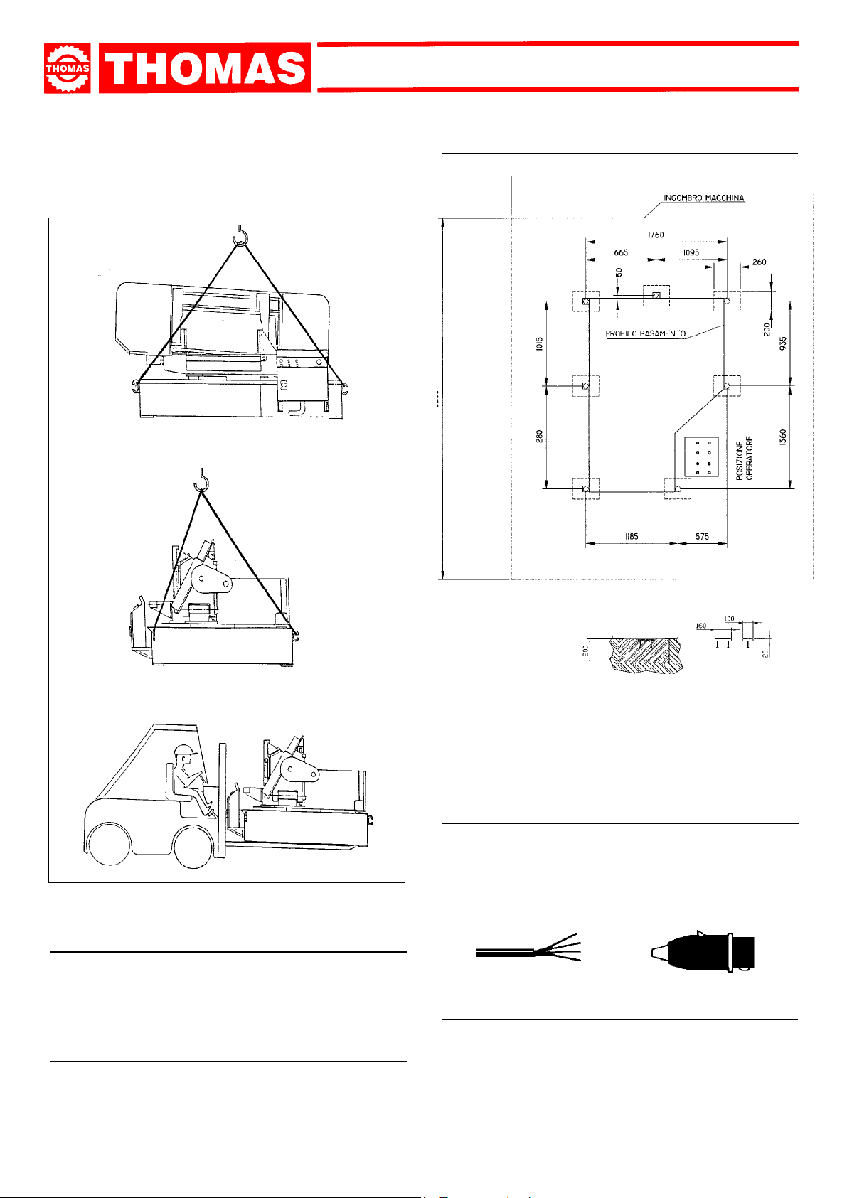
4.1 - Machine dimensions .............................................." 6
4.2 - Transport and handling of the machine ................." 7
4.3 - Minimum requirements for the premises
housing the machine.............................................. " 7
4.4 - Anchoring the machine .........................................." 7
4.5 - Instructions for electrical connection ......................" 7
4.6 - Disactivating the machine ......................................" 7
4.7 - Dismantling............................................................." 8
CHAPTER 5
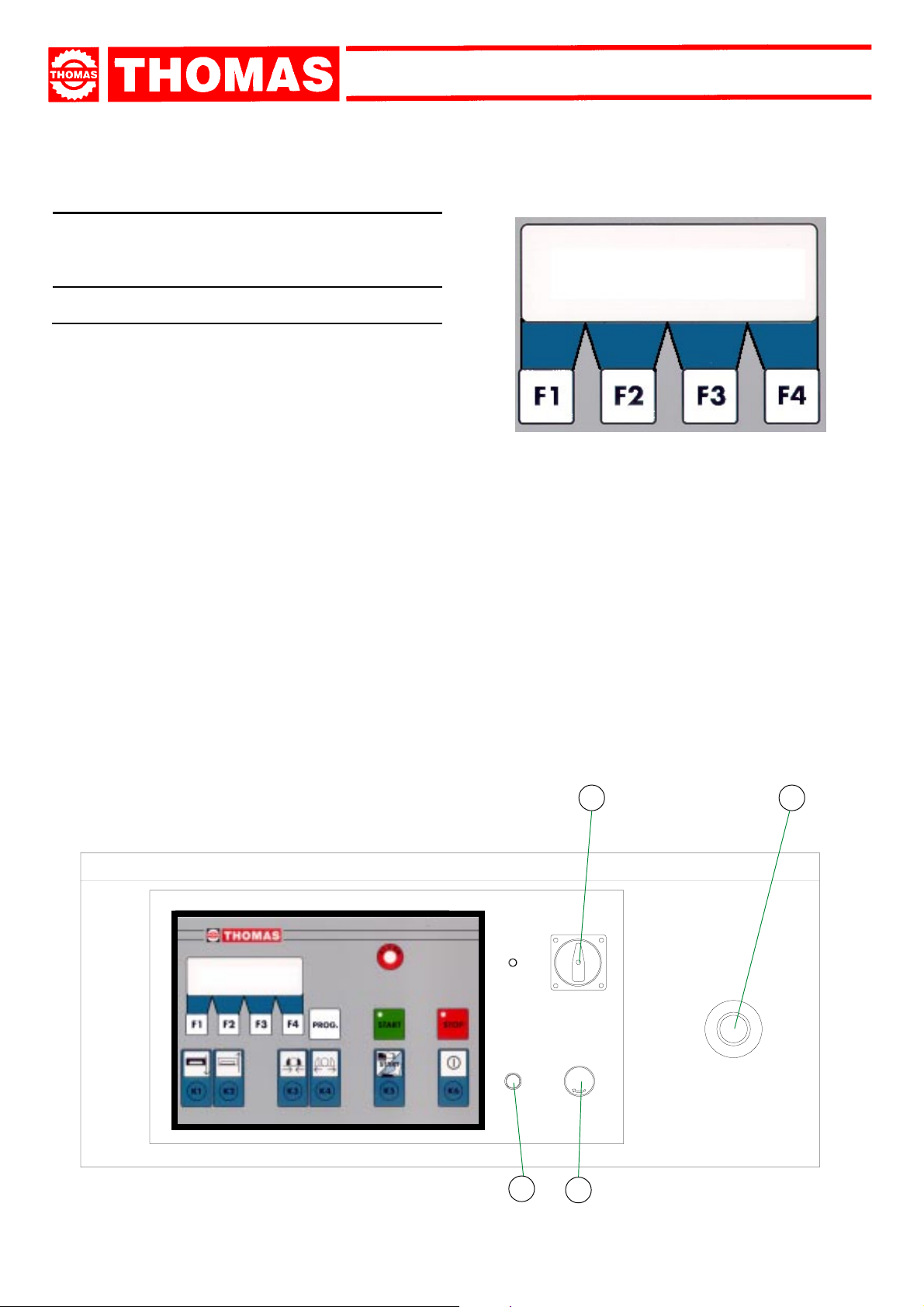
Machine functional parts .............................................. " 8
5.1 - Operating head or sawframe.................................." 8
5.2 - Vice........................................................................." 8
5.3 - Bed ........................................................................." 8
CHAPTER 6
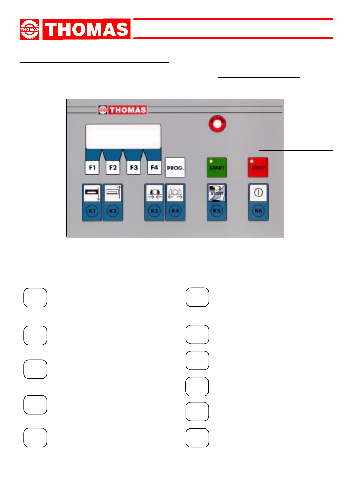
Description of the operating cycle .............................. " 9
6.1 - Starting up .............................................................." 9
6.2 - Cutting speed INVERTER ......................................" 9
6.3 - Piece-counter ........................................................." 10
6.4 - Cutting cycle ..........................................................." 10
6.5 - Sawframe return stroke limit (option) ....................." 10
6.6 - Alarm ......................................................................" 12
Orderingspareparts
- Whenorderingsparepartsyoumuststate:
MACHINE MODEL
SERIAL NUMBER
PART REFERENCE NUMBER
WithoutthesereferencesWEWILLNOTSUPPLYthespares.Seepoint10.1-listofspareparts-
Guarantee
- TheCompanyguaranteesthatthemachine,describedinthismanual,hasbeendesignedtomeetsafetyrequirements.Asformachinefunctionality,inspectionhasbeen
successful.
- Themachineisguaranteedfor12months:theguaranteedoesnotcovertheelectricmotors,electriccomponents,pneumaticcomponentsoranydamageduetodropping
ortobadmachinemanagement,thefailuretoobservemaintenancestandardsorbadhandlingbytheoperator.
- Thebuyerhasonlytherighttoreplacementofthefaultyparts,whiletransportandpackingcostsareathisexpense.
- Theserialnumberonthemachineisaprimaryreferencefortheguarantee,forafter-salesassistanceandforidentifyingthemachineforanynecessity.
CHAPTER 7
Regulating the machine ................................................ " 12
7.1 - Blade tension assembly ........................................." 12
7.2 - Blade-guides .........................................................." 13
7.3 - Vice........................................................................." 14
7.4 - Cutting angle adjustment ......................................." 14
7.5 - Vice pressure regulation ........................................" 14
7.6 - Blade cleaning brush ............................................." 14
7.7 - Changing the blade................................................" 15
CHAPTER 8
Routine and special maintenance ............................... " 15
8.1 - Daily maintenance ................................................." 15
8.2 - Weekly maintenance.............................................." 15
8.3 - Monthly maintenance ............................................." 15
8.4 - Six-monthly maintenance......................................." 15
8.5 - Oils for lubricating coolant......................................" 15
8.6 - Oil disposal ............................................................." 15
8.7 - Special maintenance.............................................." 15
CHAPTER 9
Material classification and choice of tool.................... " 16
9.1 - Definition of materials............................................." 16
9.2 - Selecting blade......................................................." 16
9.3 - Teeth pitch .............................................................." 16
9.4 - Cutting and advance speed ..................................." 17
9.5 - Blade running-in....................................................." 17
9.6 - Blade structure ......................................................." 17
9.7 - Blade type..............................................................." 17
Shape and angle of tooth ......................................." 17
Set..........................................................................." 18
9.7.1 - Table of recommended cutting parameters .............. " 18
CHAPTER 10
Machine components ................................................... " 19
10.1- List of spare parts ................................................... " 19
CHAPTER 11
Three-phase electric diagram...................................... " 30
Hydraulic electric diagram........................................... " 35
CHAPTER 12
Troubleshooting ............................................................. " 37
12.1-Blade and cut diagnosis........................................." 37
CHAPTER 13
Noise tests..................................................................... " 41
Plates and labels ........................................................... " 42

3
SAR 460 SA G
via Pasubio, 32 36033 ISOLA VIC. - ITALIA
SAR 460 SA-G
DIGIT
Machine certification and identification marking
MACHINE LABEL
TYPE
SERIAL NUMBER
YEAROFMANUFACTURE
(Space reserved for the NAME and STAMP of the DEALER and/or IMPORTER)

4
SAR460SAG
This machine has been built to comply with the national and community accident-prevention regulations in force. Improper use
and/or tampering with the safety devices will relieve the manufacturer of all responsibility.
1.1 - Advice for the operator
- Check that the voltage indicated on the plate, normally fixed to the machine motor, is the same as the line voltage.
- Check the efficiency of your electric supply and earthing system; connect the power cable of the machine to the socket and theearth
lead (yellow-green in colour) to the earthing system.
- When the saw frame is in suspend mode (up) the toothed blade must not move.
- Only the blade section used for cutting must be kept unprotected. Remove guarding by operating on the adjustable head.
- It is forbidden to work on the machine without its shields (these are all white, blue or grey in colour).
- Always disconnect the machine from the power socket before blade change or carrying out any maintenance job, even in the case
of abnormal machine operation.
- Always wear suitable eye protection.
- Never put your hands or arms into the cutting area while the machine is operating.
- Do not shift the machine while it is cutting.
- Do not wear loose clothing with sleeves that are too long, gloves that are too big, bracelets, chains or any other object that could get
caught in the machine during operation; tie back long hair.
- Keep the area free of equipment, tools or any other object.
- Perform only one operation at a time and never have several objects in your hands at the same time. Keep your hands as clean as
possible.
- All internal and/or internal operations, maintenance or repairs, must be performed in a well-lit area or where there is sufficient light
from extra sources so as to avoid the risk of even slight accidents.
1.2 - Location of shields against accidental contact with the tool
- Grey metal guards, fastened with screws onto the mobile blade-guide ensures covering of blade section not used in cutting
operation ( A ).
- Grey metal guards, fastened onto the sawframe, to protect from flywheels ( B ).
- Grey metal guard to protect from driving belts ( C ).
- Grey metal fence around the machine, to protect the operator from cutting area ( D ) .
1
REFERENCE TO ACCIDENT PREVENTION REGULATIONS
B
A
B
D
C
D

5
SAR 460 SA G
ited by screws that can only be removed with a special tool; the parts are fed with alternating current at low voltage. The equipment
is protected against splashes of water and dust.
- Protection of the system against short circuits is ensured by means of rapid fuses and earthing; in the event of motor overload,
protection is provided through the inverter.
- The machine has been tested in conformity with point 20 of EN 60204.
1.4 - Emergencies according to European Standard "CENELEC EN 60 204-1"
- In the event of incorrect operation or of danger conditions, the machine may be stopped immediately by pressing the red mushroom
button.
- The casual or voluntary removal of the protection shield of the flywheels causes the stepping-in of a microswitch that automatically
stops all machine functions.
- In case blade breaks, the pressure switch stops all machine functions.
1.5 - OTHER RISKS
- As the machine is running, any intervention from the operator within the “dangerous zone” or cutting area must be considered a
risk for his own safety.
RECOMMENDATIONS AND ADVICE FOR USE
2.1 - Recommendations and advice for using the machine
- The machine has been designed to cut metal building materials, with different shapes and profiles, used in workshops, turner’s
shops and general mechanical structural work.
- Only one operator is needed to use the machine, that must stand as shown in the picture.
2
1.3 - Electrical equipment according to Euro-pean Standard "CENELEC EN 60 204-1" which as-similates,
with some integrating modifications, the publication "IEC 204-1"
- The electrical equipment ensures protection against electric shock as a result of direct or indirect contact. The active parts of this
equipment are housed in a box to which access is lim
- Before starting each cutting operation, ensure that the part is firmly gripped in the vice and that the end is suitably supported.
These figures show examples of suitable clamping of different section bars, bearing in mind the cutting capacities of the machine in
order to achieve a good efficiency and blade durability.
- Do not use blades of a different size from those stated in the machine specifications.
- If the blade does not cut through the material, immediately strike the emergency push-button and switch off the machine. Open the
vice with the handwheel, remove part to be cut ad check that the blade teeth are not broken, If they are, replace tool.
- Check saw frame return spring to ensure proper balancing.
- Before carrying out any repairs on the machine, consult the dealer or apply to THOMAS.

6
SAR460SAG
0° 460 450 760 x 380
30° 450 440 600 x 400
45° 400 380 400 x 360
60° 210 210 210 x 280
TECHNICAL DETAILS
4
A KW
1
2
3
4
DIMENSIONE DELLA LAMA mm
DIAMETRO VOLANI mm
ALTEZZA PIANO DI LAVORO mm
APERTURA DELLA MORSA mm
VELOCITA' DI TAGLIO m/1'
RIDUTTORE Rapp.
PRESSIONE CENTRALINA
IDRAULICA Bar
PRESSIONE TENDINASTRO Bar
PESO Kg
3
TECHNICAL CHARACTERISTICS
3.1 - Table of cutting capacity and technical details
standard model
Blade dimension
Flywheel diameter
Working table heigth
Vice opening
Cutting speed
Gear-box
Hydraulic service pressure
Blade tension pressure
Weight
MOTORS
Blade motor
Hydraulic pump motor
Coolant liquid electropump
MACHINE DIMENSIONS
TRANSPORT
INSTALLATION
DISMANTLING
4.1 - Machine dimensions
5500 x 38 x 1,3
560
630
770
20 ÷ 100
INVERTER
35
22
2600
5,5
1,5
0,15
A = 2400
B = 1550
C = 630
D = 2500
E = 2360
F = 2830

7
SAR 460 SA G
R = L1
S = L2
T = L3
PE = GND
4.4 - Anchoring the machine
4.2 -Transport and handling of the machine
If the machine has to be shifted in its own packing, use a fork-lift
truck or sling it with straps as illustrated.
4.3 - Minimum requirements for the premises
housing the machine
- Mains voltage and frequency complying with the machine
motor characteristics.
- Environment temperature from -10 °C to +50 °C.
- Relative humidity not over 90%.
- Position the machine on a firm cement floor, maintaining, at
the rear, a minimum distance of 1500 mm from the wall; an-
chor it to the ground as shown in the diagram, using screws
and expansion plugs or tie rods sunk in cement, ensuring that
it is sitting level.
4.5 - Instructions for electrical connection
- The machine is not provided with an electric plug, so the cus-
tomer must fit a suitable one for his own working conditions:
1 - WIRING DIAGRAM FOR 5-WIRE SYSTEM FOR THREE-
PHASE MACHINE - SOCKET FOR A 32A PLUG
4.6 - Disactivating the machine
- If the sawing machine is to be out of use for a long period, it is advisable to
proceed as follows:
1)detach the plug from the electric supply panel
2)loosen blade
3) remove the sawframe return spring
4) empty the coolant liquid tank.

8
SAR460SAG
5
5.2 -Vice
- Material clamping system during the cutting operation by
means of a special stop pawl and hydraulic locking.
5.3 - Bed
4.7 - Dismantling
(because of deterioration and/or obsolescence)
General rules
Ifthemachine is tobepermanentlydemolished and/or scrapped,
divide the material to be disposed of according to type and
composition, as follows:
1)Cast iron or ferrous materials, composed of metal alone, are
secondary raw materials, so they may be taken to an iron
foundry for re-smelting after having removed the contents
(classified in point 3);
2)electrical components, including the cable and electronic ma-
terial (magnetic cards, etc.), fall within the category of mate-
rial classified as being assimilable to urban waste accord-
ing to the laws of the European community, so they may be
set aside for collection by the public waste disposal service;
3)old mineral and synthetic and/or mixed oils, emulsified oils
and greases are special refuse, so they must be collected,
transported and subsequently disposed of by the old oil dis-
posal service.
NOTE: since standards and legislation concerning refuse in
generalisin astateof continuous evolutionandtherefore
subject to changes and variations, the user must keep
informed of the regulations in force at the time of dis-
posing of the machine tool, as these may differ from
those described above, which are to be considered as
a general guide line.
MACHINE FUNCTIONAL
PARTS
5.1 - Operating head or saw frame
- Part of the machine consisting of drive members (gearmotor
orvariablespeed motor,flywheels),tightening andguide(blade
tightening slide, blade guide head) of tool.
- Structure supporting the SAWFRAME OPERATING HEAD
(revolving arm for degree cutting along with clamping sys-
tem), the VICE; the bedplate houses the cooling liquid TANK,
the CONTROL BOARD, ELECTRICAL and HYDRAULIC
SYSTEMSandtheDEVICECONTROLLINGtheAUTOMATIC
HYDRAULIC LOWERING AND RISE of the SAWFRAME.

9
SAR 460 SA G
DESCRIPTION OF THE
OPERATING CYCLE
Before operating, all the main organs of the machine must
be set in optimum conditions (see the chapter on “Regulat-
ing the machine”).
6
- Ensure that the machine is not in emergency stop condition; if
it is, release the red mushroom button ( 1).
- Make sure that the flywheel metal Cover is closed as well as
the relevant Microswitch.
- Rotate the main switch ( 3) towards the right to
position 1
.
- Press start button ( 2).
- Close the regulator ( 4 ) completely (turn it clockwise).
- Press the key activating the hydraulic pump (see legenda at
page 10) as well as the keys moving the sawframe and the
vice to verify if these work properly; if they doesn’t attempt to
swap one of the electric power supply wires (only during
installation).
-
ATTENTION:
having started the hydraulic unit motor, make
sure that the blade is under tension (eventually the blade
tension lever is released), so that the relevant microswitch
won't break the electrical circuit. Please refer to
para. 7.1 Blade
tension assembly
for more details.
- Press the key lifting the sawframe.
- Check the index showing the cutting angle; refer to
para. 7.4
Cutting angle adjustment
if you want to perform mitre cutting.
6.1 - Starting up and cutting cycle
1
1
34
2
- Display shows the following information soon after you switch
on the machine:
-START = start of the cutting cycle.
-PZ. I = programmed cutting cycles. The machines stops
automatically once the programmed number has been
completed; reset the piece-counter to start the machine again.
-PZ. T = programmed cutting cycles completed.
-VEL . LAMA or BLADE SPEED = current blade speed
expressed in meters per minute.
-F1: corrisponding to the sign 'PZ' goes to the programming of
the piece-counter.
-F2 : corrisponding to the sign 'STATO' goes to the visualization
checking up the machine functions.
-F4 : corrisponding to the sign 'VEL' goes to the adjustment of
the blade speed.
START = BUTTON
PC. I = PC.T =
Blade speed Mt /m= ___
PC STATO VEL

10
SAR460SAG
SAWFRAME DOWNFEED
SAWFRAME LIFT
VICE LOCK
LEGENDA CONTROLLER
CYCLE START
CYCLE STOP
ALARM WARNING LIGHT
K4 VICE OPEN
K1
K2
K5 CYCLE START SELECTION:
FOOT CONTROL SWITCH, OR
KEY ON THE CONTROLLER
HYDRAULIC PUMP ON
PROG
K6
K3
F3
F1
F2
F4
ACCESS TO THE CONTROLLER
CONFIGURATION ( ACCESS PROTECTED BY
PASSWORD ).
ACTIVATES THE FUNCTION SHOWN RIGHT
ABOVE ON THE DISPLAY
ACTIVATES THE FUNCTION SHOWN RIGHT
ABOVE ON THE DISPLAY
ACTIVATES THE FUNCTION SHOWN RIGHT
ABOVE ON THE DISPLAY
ACTIVATES THE FUNCTION SHOWN RIGHT
ABOVE ON THE DISPLAY

11
SAR 460 SA G
6.2 - Adjustment of the blade speed
INVERTER
- The INVERTER or frequency converter controls the blade
speed rotation. The range goes from 20 to 100 meters per
minute.
- Press the key corresponding to the sign 'VEL' ( F4 ) as shown
at page n. 9.
- The display shows:
- Press the keys 'F1' or 'F2' to set the correct blade speed.
- Press the key 'F4' to exit.
Note: the blade speed can be adjusted even during the cutting
phase.
6.3 - Piece-counter
- The piece-counter not only counts each cutting cycle, but it
stops the machine automatically as soon as the programmed
cutting cycle number has been completed.
- Press the key corresponding to the sign 'PZ' ( F1 )
The dispaly shows the following information.
- Press the keys 'F1' or 'F2' to set the desired number.
PZI. = number of cutting cycles to be executed.
PZT.= number of cutting cycles already executed.
RES.: to reset the visualized number of cuts.
ESC.: to go back to the initial page.
- As soon as the programmed number of cutting cycles has
been completed, a message appears and the machine stops
6.4 - Cutting cycle
- Press the key to lift the sawframe over the material to be cut.
- Open the vice and load the material.
- Rest the vice jaw on the material and make sure that the pawl
is hooked down to the rack.
- Press the key to lock the vice.
- Set the correct cutting speed ( see table at chapter 9 ).
- Set the sawframe downfeed speed on the regulator ( 4 );
initially, we recommend to set lower speed to avoid any
dangerous effect.
- Press the key START: make sure that the blade turns the right
direction, the coolant liquid flows and the cutting cycle
proceeds properly.
- Press the red emergency push button in case of incorrect
operation, or to stop the machine immediately.
- Press CYCLE STOP to stop the cutting cycle.
CUTTING DIRECTION
MOD. VELOCITA' LAMA
20 Mt/ min.
+ - ESC
MODIFICA PEZZI
PZI. = __ PZT. = __
+ - RES ESC
automatically.
- To start the machine again, reset the number of the executed
cuts by pressing the key 'F3' ( RES ).
ATTENTION: if you do not need the piece-counter, just set '0'
(zero) on the field 'PZ. I'.

12
SAR460SAG
A
7
è
REGULATING THE
MACHINE
7.1 - Blade tension
Lever ( A ) can be set to three different positions :
POSITION 1 : LOOSE
POSITION 2 : NEUTRAL
POSITION 3 : TENSION
Ensure that Lever (A) is at position 3 whenever the hydraulic
pump has been started. Also make sure the blade correctly
rests on the flywheels and runs through the blade-guides.
Manometer should indicate 22 BAR pressure as blade
tension.
A safety microswitch located on the blade tension slide,
stops the machine in case of blade breakage or insufficient
tensioning.
6.6 - Alarms
- The display shows any problem or dangerous situation.
Once the problem has been solved, press the Start key ( 2 )
and the key corresponding to the function 'RES'.
'5 FINE PEZZI' or 'PIECES END':
It stops the machine automatically as soon as the
programmed cutting cycle number has been completed.
Reset the counter.
'12 ROTTURA LAMA' or 'BROKEN BLADE'
Replace the blade or check tension.
'13 CARTER APERTO' or 'OPEN DOOR'
Close the sawframe door.
'14 FUNGO EMERGENZA' or 'EMERGENCY PUSH-
BUTTON'
Release the emergency push-button.
'15 TERMICO2 CENTRAL' or 'THERMAY PROTECTION'
Reset the thermal relay protecting the hydraulic unit.
'16 ALLARME INVERTER'
Reset the thermal relay protecting the Inverter.
The machine is now ready to start work, bearing in mind that the
CUTTING SPEED and the TYPE of BLADE - combined with a
suitable lowering of saw frame - are of decisive importance for
cutting quality and for machine performance (for further details
on this topic, see below in the chapter on “Material classifica-
tion and blade selection”).
- When starting to cut with a new blade, in order to safeguard
its life and efficiency, the first two or three cuts must be
made while exerting a slight pressure on the part, so that
the time taken to cut is about double the normal time (see
below in the chapter on “Material classification and blade
selection” in the section on
Blade running-in
).
- Press the red emergency button ( 1) when there are condi-
tions of danger or malfunctions in general, so as to stop ma-
chine operation immediately.

13
SAR 460 SA G
1
2
1
D
7.2 - Blade-guide blocks
Blade-guide adjustment was made at the factory during the
machine testing. The blade is kept perpendicular to the
workpiece by means of CARBIDE blade-guide pads. Ensure
that knob (1) is completely screwed up against the block.
Periodically check wear status of the pads; also keep the block
and the pads clean.
- The bearings guide the blade to the pads providing the
necessary inclination and reducing the torsion stress of the
blade; they do not need any adjustment or particular care.
- Adjust the blade-guide arm as follows:
Release both knob (1) and handwheel (2).
Position the arm according to the workpiece dimensions;
ensure that it doesn't hit the bench vice.
Fix both handwheels (1) and (2).
-
ATTENTION
: Make sure that the limit switch ( D ) stops the
blade-guide arm just before the working table.
The blade-
guide arm should not fall against the working table !!.
The
reference screw ( E ) can be adjusted for this purpose.
E

14
SAR460SAG
7.5 - Vice pressure regulation
( OPTION )
- Vice pressure can be adjusted through a special hydraulic
valve.
- Turn the knob ( E ) either increasing or decreasing vice
pressure.
7.4 - Cutting angle adjustment
- Screw the nut ( C ) of the vice. Screw the nuts of the circular
guide as well.
- Keep the circular guide always clean.
7.3 - Vice
- Press the function key to open the vice.
- Lift the stop pawl ( B ), and rest the vice jaw against the
workpiece.
-
Ensure that the pawl ( B ) perfectly catches with the rack
tooth.
- Press the function key to close the vice.
- Keep the rack clean to ensure that the pawl perfectly catch
with the rack.
- Keep the vice guide always clean.
- In case of mitre cutting, unscrew the nut ( C ) swinging the vice
to the required angle. Fix the nut ( C ).
- The sawframe can be swivelled from 0° to 60° to the lefthand.
This way you can have the workpiece cut at a required angle.
- Fully rise the sawframe to the top position.
- Unscrew the nut ( C ) swinging the vice to the required angle.
Uncrew the nuts of the circular guide as well.
- Press the push buttons located on the machine base ( 10 )
swivelling the sawframe to the required angle.
B
CE
7.6 - Blade cleaning brush
The brush removes the chips off the blade during the cutting
cycle. Periodically check its wearing degree, eventually adjust
or replace the metal brush.
10
LEFT RIGHT

15
SAR 460 SA G
8
CAREFULLYCARRY OUTTHE FOLLOWING
INSTRUCTIONSABOUTBLADEREPLACEMENT.
CUTTING DIRECTION
7.7 - Blade replacement
- Lift the sawframe to the top position.
- Turn the lever to
LOOSE,
and soon after to
NEUTRAL
(see
drawing below).
- Release the knob controlling the blade-guide pads.
- Open both flywheel covers and remove the blade first off the
guiding blocks, then off the flywheels.
- Mount a new blade, first through the blade-guide pads, then on the
flywheels (
pay attention to the teeth cutting direction
).
- Put the blade under tension by means of the special lever.
Gradually tension the blade making sure that it perfectly suits
to the flywheels and through the blade-guide pads.
Definitively turn the lever to
TENSION
after having made sure
that the the blade is correctly positioned.
-
Note: recommended blade tension pressure= 22 BAR.
- Ensure that the blade cleaning brush is correctly adjusted.
- Close both flywheel covers.
ATTENTION
:ensure that you are using the blade having the
same size as indicated at page 5.
RELY ON SKILLED AND QUALIFIED PERSONNEL TO
REPLACE OTHER MACHINE MEMBERS SUCH AS
REDUCTION UNIT, PUMP MOTOR AND ELECTRICAL
COMPONENTS.
ROUTINE
AND SPECIAL
MAINTENANCE
THEMAINTENANCE JOBS ARELISTEDBELOW,DIVIDED
INTO DAILY, WEEKLY, MONTHLY AND SIX-MONTHLY IN-
TERVALS. IF THE FOLLOWING OPERATIONS ARE NE-
GLECTED, THE RESULT WILL BE PREMATURE WEAR
OFTHE MACHINE AND POOR PERFORMANCE.
8.1 - Daily maintenance
- Generalcleaningof the machine toremoveaccumulated shav-
ings.
- Rack cleaning - stop pawl of the vices.
- Top up the level of lubricating coolant.
- Check blade for wear.
- Check functionality of the shields and emergency stops.
8.2 -Weekly maintenance
- More accurate general cleaning of the machine to remove
shavings, especially from the lubricant fluid tank.
- More accurate cleaning of the rack - stop pawl of the vice.
- Removal of pump from its housing, cleaning of the suction
filter and suction zone.
- Cleaning with compressed air the blade guide pads and
bearing (drain hole of the lubricating cooling).
- Cleaning flywheel housings and blade sliding surfaces on
flywheels.
-
Check transmission belt on blademotor-gearbox.
- Check blade cleaning brush.
8.3 - Monthly maintenance
- Check the tightening of the motor flywheel screws.
- Check the tightening of the transmission flywheel ring nut.
- Check that the blade guide bearings on the heads are perfect
running condition.
- Check the tightening of the screws of the pump and accident
protection guarding.
- Check shields.
8.4 - Six-monthly maintenance (every 2000 hours)
REDUCTION UNIT
- Complete oil change (use GEARCO 85 W 140 of 'National', or
KLUBER SINTHESO EP 460 or equivalent).
HYDRAULIC UNIT
- Complete oil change(use SHELL TELLUS T32 or equivalent).
- Check continuity of the equipotential protection circuit.
8.5 - Oils for lubricating coolant
Considering the vast range of products on the market, the user
can choose the one most suited to his own requirements, using
as reference the type SHELL LUTEM OIL ECO.THE MINIMUM
PERCENTAGE OF OIL DILUTED IN WATER IS 8 - 10 %.
8.6 - Oil disposal
The disposal of these products is controlled by strict regula-
tions. Pleasesee theChapteron“Machine dimensions -Trans-
port - Installation” in the section on
Dismantling
.
8.7 - Special maintenance
Special maintenance operations must be carried out by skilled
personnel. However, we advise contacting THOMAS or their
dealer and/or importer. Also the reset of protective and safety
equipment and devices, of the reducer, the motor, the motor
pump and electric components is to be considered extraordi-
nary maintenance.

16
SAR460SAG
TYPES OF STEEL CHARACTERISTICS
USE I
UNI D
DIN F
AF NOR GB
SB USA
AISI-SAE Hardness
BRINELL
HB
Hardness
ROCKWELL
HRB R=N/mm²
Construction
steels Fe360
Fe430
Fe510
St37
St44
St52
E24
E28
E36
----
43
50
----
----
----
116
148
180
67
80
88
360÷480
430÷560
510÷660
Carbon
steels
C20
C40
C50
C60
CK20
CK40
CK50
CK60
XC20
XC42H1
----
XC55
060 A 20
060 A 40
----
060 A 62
1020
1040
1050
1060
198
198
202
202
93
93
94
94
540÷690
700÷840
760÷900
830÷980
Spring
steels 50CrV4
60SiCr8 50CrV4
60SiCr7 50CV4
---- 735 A 50
---- 6150
9262 207
224 95
98 1140÷1330
1220÷1400
Alloyed steels for
hardening and
tempering and for
nitriding
35CrMo4
39NiCrMo4
41CrAlMo7
34CrMo4
36CrNiMo4
41CrAlMo7
35CD4
39NCD4
40CADG12
708 A 37
----
905 M 39
4135
9840
----
220
228
232
98
99
100
780÷930
880÷1080
930÷1130
Alloyed
casehardening
steels
18NiCrMo7
20NiCrMo2
----
21NiCrMo2
20NCD7
20NCD2
En 325
805 H 20
4320
4315
232
224
100
98
760÷1030
690÷980
Alloyed for
bearings 100Cr6 100Cr6 100C6 534 A 99 52100 207 95 690÷980
Tool steel 52NiCrMoKU
C100KU
X210Cr13KU
58SiMo8KU
56NiCrMoV7C100K
C100W1
X210Cr12
----
----
----
Z200C12
Y60SC7
----
BS 1
BD2-BD3
----
----
S-1
D6-D3
S5
244
212
252
244
102
96
103
102
800÷1030
710÷980
820÷1060
800÷1030
Stainless
steels
X12Cr13
X5CrNi1810
X8CrNi1910
X8CrNiMo1713
4001
4301
----
4401
----
Z5CN18.09
----
Z6CDN17.12
----
304 C 12
----
316 S 16
410
304
----
316
202
202
202
202
94
94
94
94
670÷885
590÷685
540÷685
490÷685
Copper alloys
Special brass
Bronze
Aluminium copper alloy G-CuAl11Fe4Ni4 UNI 5275
Special manganese/silicon brass G-CuZn36Si1Pb1 UNI5038
Manganese bronze SAE43 - SAE430
Phosphor bronze G-CuSn12 UNI 7013/2a
220
140
120
100
98
77
69
56,5
620÷685
375÷440
320÷410
265÷314
Cast iron Gray pig iron G25
Spheroidal graphite cast iron GS600
Malleable cast iron W40-05
212
232
222
96
100
98
245
600
420
MATERIAL
CLASSIFICATION AND
CHOICE OF TOOL
9
Since the aim is to obtain excellent cutting quality, the vari-
ous parameters such as hardness of the material, shape
and thickness, transverse cutting section of theparttobe
cut, selection of the type of cutting blade, cutting speed
and control of saw frame lowering.These specifications
must therefore be harmoniously combined in a single oper-
ating condition according to practical considerations and
common sense, so as to achieve an optimum condition that
does not require countless operations to prepare the ma-
chine when there are many variations in the job to be
performed.The various problems that crop up from time to
time will be solved more easily if the operator has a good
knoledge of these specifications.
WE THEREFORE RECOMMEND YOU TO ALWAYS USE
GENUINE"THOMAS"SPARE BLADESTHATGUARANTEE
SUPERIOR QUALITY AND PERFORMANCE.
9.1 - Definition of materials
The table at the foot of the page lists the characteristics of the
materials to be cut, so as to choose the right tool to use.
9.2 - Selecting blade
First of all the pitch of the teeth must be chosen, in the other
BLADE TEETH SELECTION TABLE
THICKNESS MM Z CONTINUOUS
TOOTH DESIGN Z COMBO
TOOTH DESIGN
TILL 1.5 14 10/14
FROM 1 TO 2 8 8/12
FROM 2 TO 3 6 6/10
FROM 3 TO 5 6 5/8
FROM 4 TO 6 6 4/6
MORE THAN 6 4 4/6
S = THICKNESS
words, the number of teeth per inch (25,4 mm) suitable for the
material to be cut, according to these criteria:
- parts with a thin and/or variable section such as profiles, pipes
and plate, need close toothing, so that the number of teeth
used simultaneously in cutting is from 3 to 6;
- parts with large transverse sections and solid sections need
widely spaced toothing to allow for the greater volume of the
shavings and better tooth penetration;
- parts made of soft material or plastic (light alloys, mild bronze,
teflon, wood, etc.) also require widely spaced toothing;
- pieces cut in bundles require combo tooth design.
9.3 -Teeth pitch
As already stated, this depends on the following factors:
- hardness of the material
- dimensions of the section
- thickness of the wall

17
SAR 460 SA G
9.7 - Blade type
They differ essentially in their constructive characteristics, such
as:
-shape and cutting angle of tooth
-pitch
-set
Shape and angle of tooth
REGULAR TOOTH: 0° rake and constant pitch.
Most common form for transversal or inclined cutting of solid
small and average cross-sections or pipes, in laminated mild
steel and grey iron or general metal.
POSITIVE RAKE TOOTH: 9° - 10° positive rake and constant
pitch.
positive
Particular use for crosswise or inclined cuts in solid sections or
large pipes, but above all harder materials (highly alloyed and
stainless steels, special bronze and forge pig).
COMBO TOOTH: pitch varies between teeth and consequently
varying teeth size and varying gullet depths. Pitch varies be-
tween teeth which ensures a smoother, quieter cut and longer
blade life owing to the lack of vibration.
SOLID Ø OR L MM Z CONTINUOUS
TOOTH DESIGN
Z COMBO
TOOTH DESIGN
TILL 30 85/8
FROM 30 TO 60 6 4/6
FROM 40 TO 80 4 4/6
MORE THAN 90 3 3/4
Ø = DIAMETER L = WIDTH
9.4 - Cutting and advance speed
The cutting speed (m/min) and the advance speed (cm2/min =
area travelled by the blade during removal of chip) are limited
by the development of heat close to the tips of the teeth.
- The cutting speed is subordinate to the resistance of the ma-
terial (R = N/mm2), to its hardness (HRC) and to the dimen-
sions of the widest section.
- Too high an advance speed (= lowering of the saw frame)
tends to cause the blade to deviate from the ideal cutting path,
producing non rectilinear cuts on both the vertical and the
horizontal plane.
The best combination of these two parameters can be seen
directly examining the chips.
Long spiral-shaped chips indicate ideal
cutting.
Very fine or pulverized chips indicate lack
of feed and/or cutting pressure.
Thick and/or blue chips indicate overload
of the blade.
9.5 - Blade running-in
When cutting for the first time, it is good practice to run in the
tool making a series of cuts at a low advance speed
(= 30-35 cm2/min on material of average dimensions with re-
spect to the cutting capacity and solid section of normal steel
with R = 410-510 N/mm2), generously spraying the cutting
area with lubricating coolant.
9.6 - Blade structure
Bi-metal blades are the most commonly used. They consist in a
silicon-steel blade backing with electron beam or laser welded
high speed steel (HHS) cutting edge. The type of stocks are
classified in M2, M42, M51 and differ from each other because
of their major hardness due to the increasing percentage of
Cobalt (Co) and molybdenum (Mo) contained in the metal alloy.
distance between teeth
Another advantage offered in the use of this type of blade in the
fact that with an only blade it is possible to cut a wide range of
different materials in size and type.
COMBO TOOTH: 9° - 10° positive rake.
positive
This type of blade is the most suitable for the cutting of section
bars and large and thick pipes as well as for the cutting of solid
bars at maximum machine capacity. Available pitches: 3-4/4-6.

18
SAR460SAG
This set is associated with very fine teeth and it is mainly used
for the cutting of pipes and thin section bars (from 1 to 3 mm).
ALTERNATE SET (IN GROUPS): Groups of cutting teeth right
and left, alternated by a straight tooth.
This set is associated with very fine teeth and it is used for
extremely thin materials (less than 1 mm).
ALTERNATE SET (INDIVIDUALTEETH): Cuttingteethrightand
left.
Thisset isused forthecuttingofnonferroussoftmaterials,plastics
and wood.
Set
Saw teeth bent out of the plane of the saw body, resulting in a
wide cut in the workpiece.
REGULAR OR RAKER SET: Cutting teeth right and left, alter-
nated by a straight tooth.
Of general use for materials with dimensions superior to 5 mm.
Used for the cutting of steel, castings and hard nonferrous ma-
terials.
WAVY SET: Set in smooth waves.
9.7.1 - RECOMMENDED CUTTING PARAMETERS
STEEL CUTTING SPEED LUBRICATION REMOVAL cm²/min
CONSTRUCTION 60/80 EMULSIFIABLE OIL 40/60
CEMENTATION 40/50 EMULSIFIABLE OIL 20/40
CARBON STEEL 40/60 EMULSIFIABLE OIL 40/60
HARDENING AND TEMPERING 40/50 EMULSIFIABLE OIL 30/50
BEARINGS 40/60 EMULSIFIABLE OIL 15/30
SPRINGS 40/60 EMULSIFIABLE OIL 10/30
FOR TOOLS 30/40 EMULSIFIABLE OIL 6/20
FOR VALVES 35/50 EMULSIFIABLE OIL 20/30
STAINLESS STEEL 30/40 EMULSIFIABLE OIL 6/20
SPHEROIDAL GRAPHITE 20/40 EMULSIFIABLE OIL 6/30
CAST IRON 40/60 EMULSIFIABLE OIL 30/60
ALUMINIUM 80/600 KEROSENE 60/450
BRONZE 70/120 EMULSIFIABLE OIL 40/70
HARD BRONZE 30/60 EMULSIFIABLE OIL 6/20
BRASS 70/350 EMULSIFIABLE OIL 25/80
COPPER 50/720 EMULSIFIABLE OIL ------

19
SAR 460 SA G
10
MACHINE COMPONENTS
10.1 - List of spare parts
TABLE 1
N. DESCRIPTION
01 ..................... Base
02 ..................... Coolant tank level
03 ..................... Electropump
04 ..................... Electric component box
05 ..................... Righthand angle guide
06 ..................... Screw
07 ..................... Electropump plate
08 ..................... Screw
09 ..................... Coolant filter
10 ..................... Screw
11 ..................... Central support
12 ..................... Screw
13 ..................... Lefthand angle guide
14 ..................... Screw
15 ..................... Nut
16 ..................... Screw
17 ..................... Stop block
18 ..................... Cover
19 ..................... Box supporting square (R)
20 ..................... Box support square (L)
21 ..................... Beraing housing
22 ..................... Beraing 6205 2Z
23 ..................... Screw
24 ..................... Motherscrew
25 ..................... Nut
26 ..................... Screw
27 ..................... Motor for swivelling system
28 ..................... Bearing 6004
29 ..................... Plate
30 ..................... Pin
31 ..................... Pin
32 ..................... Screw
TABLE 2
N. DESCRIPTION
01 ..................... Countervice support
02 ..................... Washer
03 ..................... Screw
04 ..................... Material support (loading side)
05 ..................... Screw
06 ..................... Vice support
07 ..................... Vice
08 ..................... Rack
09 ..................... Stop pawl
10 ..................... Vice gib
11 ..................... Pin
12 ..................... Pin
13 ..................... Screw
14 ..................... Vice guide
15 ..................... Front plate of vice cylinder
16 ..................... Screw
17 ..................... Spring
18 ..................... Piston
19 ..................... Guarnizione USH 60 A
20 ..................... Cilindro morsa
21 ................. Ring 'OR'
22 ................. Cylinder rear flange
23 ................. Screw
24 ................. Material support (unloading side)
25 ................. Pin
26 ................. Countervice
27 ................. Screw
28 ................. Block
29 ................. Screw
30 ................. Washer
TABLE 3
N. DESCRIPTION
01 .................. Gear-box housing
02 .................. Wrench
03 .................. Worm screw shaft
04 .................. Bearing 6206
05 .................. Cover (L)
06 .................. Screw
07 .................. Stop ring
08 .................. Protection support
10 .................. Nut
11 .................. Bearing 51204
12 .................. Specer
13 .................. Hinged pin
14 .................. Bushing
15 .................. Screw
16 .................. Threaded pin
17 .................. Washer
18 .................. Washer
19 .................. Screw
20 .................. Driving belt protection
21 .................. Bushing
22 .................. Bearing 6207
23 .................. Spacers
24 .................. Ring Seeger Ø 35
25 .................. Bearing 51307
26 .................. Springs
27 .................. Joint SM 35 50 7
28 .................. Belt 3V 475
29 .................. Driven pulley
30 .................. Threaded rod
31 .................. Plate guide
32 .................. Motor support plate
33 .................. Nut
34 .................. Wrench
35 .................. Motor for blade rotation
36 .................. Motor pulley
37 .................. Flange
38 .................. Screw
39 .................. Motor pulley for blade cleaning brush
40 .................. Driving belt for blade cleaning brush

20
SAR460SAG
N. DESCRIPTION
01 .................... Gear-box housing
02 .................... Washer
03 .................... Screw
04 .................... Worm wheel
05 .................... Worm wheel bushing
06 .................... Joint
07 .................... Worm wheel shaft
08 .................... Bearing 32012
09 .................... Bearing spacer
10 .................... Motor flywheel cover
11 .................... Stop ring
12 .................... Nut
13 .................... Sawframe
14 .................... Screw
15 .................... Motor flywheel
16 .................... Screw
17 .................... Flange of motor flywheel
18 .................... Flange
TABLE 4
TABLE 5
N. DESCRIPTION
01 .................... Sawframe
02 .................... Driven flywheel cover
03 .................... Driven flywheel
04 .................... Driven flywheel shaft
05 .................... Bearing 32209 A
06 .................... Spacer
07 .................... Screw
08 .................... Stop ring
09 .................... Nut M 45
10 .................... Driven flywheel flange
13 .................... Greasing point
14 .................... Slide support for blade tension
15 .................... Slide for blade tension
16 .................... Slide gibs
17 .................... Nut
18 .................... Washer
19 .................... Front part of blade tension cylinder
20 .................... Ring 'OR'
21 .................... Ring 'OR'
22 .................... Blade tension cylinder
23 .................... Piston of blade tension cylinder
24 .................... Ring 'OR'
25 .................... Joint DH28
26 .................... Rear part of blade tension cylinder
27 .................... Screw for blade tension adjustment
28 .................... Screw
29 .................... Reference plates
30 .................... Screw
31 .................... Adjusting screw
32 .................... Washer
33 .................... Screw
34 .................... Screw
35 .................... Washer
36 .................... Screw
37 .................... Washer
38 .................... Screw
TABLE 6
04 .................Screw
05 .................Screw
06 .................Blade-guide arm
07 .................Gib
08 .................Plate
09 .................Washer
10 .................Screw
11 .................Fixed blade-guide block
12 .................Joint
13 .................Washer
14 .................Nut
15 .................Spacer
16 .................Bearing 6201
17 .................Screw
18 .................Washer
19 .................Screw
20 .................Screw
21 .................Spacer
22 .................Pin
23 .................Spring
24 .................Knob
25 .................Pin
26 .................Lateral blade-guide pad (R)
27 .................Top blade-guide pad
28 .................Lateral blade-guide pad (L)
29 .................Mobile blade-guide block
30 .................Pin
31 .................Mobile blade-guide arm
32 .................Threaded pin
33 .................Handwheel
34 .................Screw
TABLE 7
NR. DESCRIZIONE
1ª SERIE
01 .................... Brush
02 .................... Shaft
03 .................... Guard
04 .................... Shaft
05 .................... Support
06 .................... Swivel joint
07 .................... Bush
2ª SERIE
01 .................... Guard
02 .................... Pulley
03 .................... Pulley shaft
04 .................... Bearing
05 .................... Spacer
06 .................... support
07 .................... Screw
08 .................... Pin
09 .................... Belt
10 .................... Screw
11 .................... Ring
12 .................... Brush
13 .................... Nut
14 .................... Handwhell
15 .................... support
16 .................... Screw
17 .................... Guard
18 .................... Screw
19 .................... Bracket
20 .................... Bush
21 .................... Brush shaft
22 .................... Swivel joint
23 .................... Shaft
N. DESCRIPTION
01 .................Slide
02 .................Scale
03 .................Pin
Table of contents
Other Thomas Industrial Equipment manuals

Thomas
Thomas Helimel User manual

Thomas
Thomas Adaptmatic User manual

Thomas
Thomas C1013 User manual

Thomas
Thomas A1008 User manual

Thomas
Thomas 3327 User manual

Thomas
Thomas 6512 User manual

Thomas
Thomas 836 User manual

Thomas
Thomas 8218 User manual

Thomas
Thomas 358 User manual

Thomas
Thomas Alpha Plus User manual
Popular Industrial Equipment manuals by other brands

Meade
Meade ACF 0.68x manual

Spida Machinery
Spida Machinery Mini 10 Operation & service manual

SKF
SKF VP Series Component Lifecycle Manual

Axi
Axi STS Series INSTRUCTION, OPERATING, & MAINTENANCE MANUAL

TE Connectivity
TE Connectivity RBK-X1 instruction sheet

Siemens
Siemens 3VL91125GB30 operating instructions