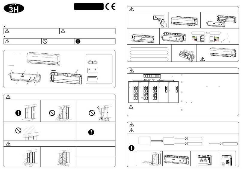
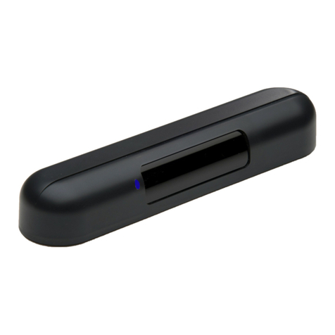
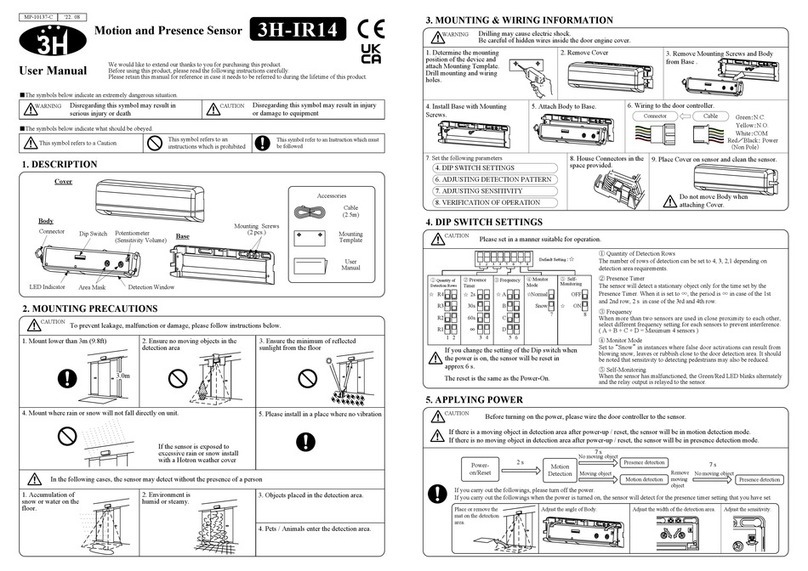
Hotron KABUTO User manual

KABUTO
User Manual
English
Installation
Instruction
Accessories
Mounting Screws
(3 pcs.)
1. DESCRIPTION
2. DIMENSIONS
3. LED INDICATORS (Operation LED)
Disregarding this
symbol may result in
serious injury or death
Note Special attention is required when this symbol is shown
WARNING
!CAUTION
!
6.5m
(23.1ft)
A B
Mounting height of
6.5m (21.3ft) or lower Adjust the sensor body
so that the sensor does
not detect the door.
Ensure there are no
moving objects in the
detection zone
Use different frequency
settings for sensors in
close proximity
Ensure the minimum of
reflected sunlight from
the floor
4. MOUNTING PRECAUTIONS
Ensure no condensation
gets onto the sensor.
If possible ensure no
accumulation of snow or
water on the floor.
Green Standby
Green blinking Sensor Initializing
Red Infrared Detecting / RADAR and Infrared Detecting
Red blinking RADAR Detecting
Yellow Inner detection "ROW 1" is detecting door movement
Green/Red blinking (Fast) Internal Sensor Error
5. TECHNICAL SPECIFICATIONS
2.87 [lb.] (1.3 [kg])
Mounting Screw 3pcs.,
Installation Instruction
Remote Control "KABUTO-RC" sold separately
-20 to +60 [Deg.C],(-4 to 140 Deg.F)
Below 80%
Model Name KABUTO
Installation Height 3.5-6.5[m] (11.5-21.3 [ft])
Weight
Accessories
Black
Operating Temperature
Operating humidity
Supply Voltage AC/DC 12 to 24 [V] ±10% 50/60Hz
Power Consumption AC12V-2.5 [VA] (Max) AC24V-3.3 [VA] (Max)
DC12V-150 [mA] (Max) DC24V-80 [mA] (Max)
Color
IP Rate IP65
Common Specification
Specifications of Reflection Sensor
Opto Relay Non Pole
Voltage: 48 [VDC] Max.
Current : 300 [mA] Max. (Resistance load)
Output
Output1
(IR.Output)
Output2
(Radar Output)
Active Infrared ReflectiveDetection Method
Output Holding Time
Presence Timer 30 [seconds], 1,2,5,10,20[minutes],1,2 [hours] or ∞
0.25 [seconds] App.Response Time
Specifications of Redar Sensor
Detection Method
0.5 [seconds] App.Output Holding Time 0.1 [seconds] App.Response Time
Transmit frequency 24.15 [GHz]
Doppler method: ( moving body detection)
Notice: Specification may be changed without prior notice.
The Radar part of the
KABUTO sensor may
be negatively influenced
by metal close to or in
the detection field
Opto Relay Non Pole
Voltage: 48 [VDC] Max.
Current : 300 [mA] Max. (Resistance load)
Sensor body
6. MOUNTING & WIRING INFORMATION
②Drill a hole to match the mounting hole
in the mounting bracket. (3.5mmφ)
Drilling may cause electric shock.
Be careful of hidden wires inside the door engine cover.
⑤Wiring to the door controller.
WARNING
!
Radar sensor unit
Infrared sensor unit
Radar sensor detection
area adjustment
③Attach the mounting bracket with the
mounting screws provided. ④Attach the sensor body to its mounting bracket.
Route the cable around the mounting bracket.
Cable
(Radar Output)
Mounting Bracket
①Remove the sensor body from its mounting
bracket.
0.5 [seconds] App.
Remote control
confirmation LED
(Blue, Yellow &
Red)
Operation LED
(Red, Green)
Remote control
receiver
Cable 10[m] ※Directly from the sensor.
68.5mm(2.69")
140mm (5.51")
(70mm (2.76"))
165mm(6.49") = Standard Mounting Pitch
(82.5mm (3.24"))
10°10°
230mm(9.06")
Disregarding this symbol may
result in injury or damage to
equipment
Side View
Recommended screw tightening torque : 5.2N・m
Sensor’s
Cable
Red
Black
White
Green
Yellow
Gray(+)
Blue
Brown(-)
(IR. Output)
AC/DC
12 to 24 [V]
±10%
Opto
Relay
Power
(Non Pole)
do not connect
do not connect
Opto
Relay Output1
Output2
MP-10332 '19.12
-1--1--1-
-1-

Radar
Approach
Only
Approach
Only IR.
Approach
Only
Default settings are shown in bold
When more than two sensors are installed
in close proximity select different
frequency settings for each sensor to
prevent cross interference.
7. REMOTE CONTROL OPERATION / FUNCTION LIST
Description
The sensor will detect a stationary object
for the preset presence timer setting on
the inner 5 rows.
Possible Setting Options(Press the desired button)
Function
Infrared (IR)
Presence
Timer
Infrared (IR)
Frequency
The number of rows of IR detection can
be configured.
Reduces malfunctions due to snowfall.
Direction
Detection
Set the IR. detection sensitivity.
Set the IR. detection width for the left
side of the sensor.
Set the IR. detection width for the right
side of the sensor.
1rows
1
(Low)
NO/NO
L0
1
(Low)
R0
NO/NC NC/NC
2rows
2
L2
3rows
L4
4rows
5
L6
5rows
6
(High)
2 3 4 6 7 8 9
(High)
R2 R4 R6
On
Function
selection
button
B
1min
On
C
2min
D
5min 10min 20min 1h ∞
Low
(Fix)Mid.
(Fix)High
(Fix)
On
NC/NO
Both
Off
5
Off
Off
Off
2h
A
#
Complete
button
Vehicle
Vehicle and
people
Low
(Auto)Mid.
(Auto)High
(Auto)
3 4
A
B
C
E
F
G
H
D
A
B
C
D
E
F
↑
↑
↑
↑
↑
↑
Relay
Output
(IR./Radar)
Radar
Sensitivity
Infrared (IR)
Sensitivity
Cross Traffic
Infrared (IR)
Detection -
Width
Adjustment -
Right Side
Infrared (IR)
Detection -
Width
Adjustment -
Left Side
Infrared (IR)
Detection
Rows
Insect mode
Environment
(snow) mode
Vibration
mode
Infrared (IR)
detection
target
Set the radar detection sensitivity.
Reduce malfunction caused by insects.
Reduce malfunction due to sensor body
vibrations.
The detection target for the IR detection
area can be set to “Vehicle and people” or
“Vehicle only”.
This function prevents the sensor from
detecting an object that moves away from
the sensor.
Infrared (IR) direction detection works
only when all IR. detection spots are
active. (5x12 spots)
This function prevents the sensor from
detecting movement parallel to the door.
Infrared (IR) Cross traffic only works
when all IR.
detection spots are active. (5x12 spots)
Set the relay output status (IR/Radar)
When set to any of the (Fix)
settings, the sensor operates in this
state irrespective of the outside
temperature.
1 / 2
30s
Radar
1 / 2 1 / 2 1 / 2
The Radar detection area targets
vehicle, not people.
Detection Rows and Detection
Width can be set independently.
Example
3rows
L2 R4
When set to any of the (Auto) settings, the
sensor will operate in the selected setting
at temperatures of below 5°C. At
temperatures of above 5°C Environment
mode is disabled.
IR.
12 3 4 5 6 7 8 9
Radar
IR.
Radar
IR.
Radar
IR.
IR. IR. IR. IR.
Radar Radar Radar Radar
IR.
On Radar
On
KABUTO-RC Remote Control (Sold Separately)
-2-

-3-
Setting
confirmation
button
Function
selection
button
#
Confirm
button
H
Function
selection
button
#H
A~
FA ~
↑
*#
The green LED flashes 1 to 9 times to confirm the
actual sensor setting. (Refer to section 7)
Visual confirmation
↑
8. CHECK THE SETTINGS
Cancel permanent
activation of the relay
9. MAINTENANCE MODE
Return to factory
settings Soft reset
Restart the sensor.
Function
selection
button
I↑
Possible Setting Options(Press the desired button)
9 9
10. SETTING AND CLEARING A FOUR DIGIT SECURITY
I↑9
1~1~91~91~
999
#
I 9 91~1~91~91~
Setting a
security code
Unlocking the
security code
Clearing the
security code
Press a 4-digit number
Complete
button
Complete
button
Complete
button
Choose Choose Choose Choose
Function
The setting of any
sensor function can be
checked as follows
This setting is used
during maintenance.
#
H
↑
*
A
B
C
E
F
G
H
D
A
B
C
E
F
D
↑
↑
↑
↑
↑
↑
↑
↑I
Blue Yellow Red
I
Button Flashing OffOn
11. LED INDICATORS (Remote control LED)
Function
IR. Presence Timer
IR. Frequency
Direction Detection
Relay Output (IR./Radar)
Radar Sensitivity
IR. Sensitivity
Cross Traffic
IR. Right width
IR. Row
Insect mode
Environment (snow) mode
Vibration mode
Maintnance mode
IR. Left width
IR. detection target
Access code operation
Complete
Setting confirmation
When “1” is selected
Unlocking security code complete
Unlocking security code
Setting/Clearing a security code
Permanently activate the
relay to open the door so that
the position of detection row
1 can be checked.
1234
* If the [1-9] button are not pressed and the [#] button is pressed, the last selected [1-9] button becomes valid.
* When the [#] button is pressed after pressing the [1-9] button the setting is confirmed and the setting is saved.
* The last function selected on the remote control is the one that will be changed when buttons (1-9) are pressed.
(Example A - C followed by pressing 2 will set Cross Traffic to ON)
* If you press the [#] button without pressing the [1-9] button, you will exit the setting state without any setting been saved. (Example A - #)
* You can change from one function setting to another as much as you like until the [#] button is pressed.
When the Complete button # is pressed the sensor LED blinks green to indicated registration.

12.DETECTION AREA WIDTH AND DEPTH ADJUSTMENT
Detection Area Depth Adjustment: Infrared-IR
(
5 Rows
)
When mounted on the wall When ceiling mounted 【Far 】
32°(Far)
16°(Near)
【Near 】
-4-
0
1.0 02.03.04.05.06.07.0
1.0
2.0
3.0
4.0
5.0
6.0
6.5
3.5
[m]
1.0 02.03.04.0 0
1.0
2.0
3.0
4.0
5.0
6.0
6.5
3.5
[m]
1.01.0 2.02.0 3.03.0 4.04.0 0
1.0
2.0
3.0
4.0
5.0
6.0
6.5
3.5
0
[m]
1.01.0 2.02.0 3.03.0 4.04.0 0
1.01.0 2.02.0 3.03.0 4.04.0 0
[m]
[m]
0
1.0
2.0
3.0
4.0
5.0
6.0
7.0
0
1.0
2.0
3.0
4.0
5.0
6.0
7.0
Installation Height: 3500mm
1.01.0 2.02.0 3.03.0 4.04.0 0
1.0
2.0
3.0
4.0
5.0
6.0
6.5
3.5
0
[m]
1.01.0 2.02.0 3.03.0 4.04.0 0
1.01.0 2.02.0 3.03.0 4.04.0 0
[m]
[m]
0
1.0
2.0
3.0
4.0
5.0
6.0
7.0
0
1.0
2.0
3.0
4.0
5.0
6.0
7.0
Detection Area Width : Infrared
(
5 Rows
)
Installation Height: 5000mm
0° 0°
32°(Far)
16°(Near)
【When the sensor body angle is set to 32° (Far)】 【When the sensor body angle is set to 16° (Near)】
Beam positions at row 1
Infrared floor pattern

-5-
Installation Height: 3500mm
Detection Area Width : RADAR
CAUTION
!The above illustrated detection areas represent the actual position of the infrared and radar beams. The actual detection area observed will vary depending
on the sensor installation environment, objects been detected and sensor settings.
Detection Area Depth Adjustment: RADAR
The detection area varies depending on the object size and approach speed.
The Radar is design to detect only large objects and not people.
The radar swings from the third row of infrared detection spots as its base point.
25°(Far) -10°(Near)
Turn left or right
0°(IR. 3 row)
1.02.03.04.06.0 5.07.08.09.0 0 0
2.0
3.5
4.0
6.0
6.5
[m]
32°
(Sensor body angle)
Far Near
1.0
3.0
5.0
0
2.0
4.0
6.0
6.5
3.5
【When the sensor body angle is set to 16° 】
01.02.03.0 1.0
[m]
+25°
-10°
4.05.0
1.0
3.0
5.0
【When the sensor body angle is set to 32°】 【When the sensor body angle is set to 16°】
※Maximum sensitivity
1.01.0 2.02.0 3.03.0 4.04.0 01.01.0 2.02.0 3.03.0 4.04.0 0
1.01.0 2.02.0 3.03.0 4.04.0 0 1.01.0 2.02.0 3.03.0 4.04.0 0
[m][m]
[m][m]
0
1.0
2.0
3.0
4.0
5.0
6.0
7.0
0
1.0
2.0
3.0
4.0
5.0
6.0
7.0
0
1.0
2.0
3.0
4.0
5.0
6.0
7.0
0
1.0
2.0
3.0
4.0
5.0
6.0
7.0
8.0 8.0
8.08.0
【When the sensor body angle is set to 32° 】
-10°
Far Near
16°
(Sensor body angle)
+25°
Installation Height: 5000mm
Radar angle:25°
Radar angle:-10° Radar angle:-10°
Radar angle:25°
Radar angle:-10°
Radar angle:25°
Radar angle:-10°
Radar angle:25°
If the RADAR detects people, decrease its sensitivity setting.

-6-
14. KABUTO EC DECLARATION OF CONFORMITY
Product Description:
KABUTO combined motion and presence detection sensor for automatic doors.
Technology used : Active Infrared Technology and Doppler Method Radar Technology
Directives Fulfilled:
KABUTO is in conformity with the basic requirements of the directives 2014/53/EU and 2011/65/EU.
<Disclaimer >The manufacturer cannot be held responsible for below.
1. Misinterpretation of the installation instructions, miss connection, negligence, sensor modification and inappropriate installation.
2. Damage caused by inappropriate transportation.
3. Accidents or damages caused by fire, pollution, abnormal voltage, earthquake, thunderstorm, wind, floods and other acts of providence.
4. Losses of business profits, business interruptions, business information losses and other financial losses caused by using the sensor or malfunction of the sensor.
5. Amount of compensation beyond selling price in all cases.
MP-10332 '19.12
26 Dublin Street (2nd Floor), Carlow, Ireland
URL: http://www.hotron.com
Fax: +353-(0)59-9140543
Phone: +353-(0)59-9140345
1-11-26 Hyakunin-Cho, Shinjuku-Ku, Tokyo, Japan
URL: http://www.hotron.com
Fax: +81-(0)3-5330-9222
Phone: +81-(0)3-5330-9221
Manufacturer
HOTRON CO.,LTD. SALES Europe
Hotron Ireland Ltd.
13. TROUBLESHOOTING
Detection row “ROW1” is detecting too close to the door.
LED Status Possible Cause Solution
OFF
Door opens and closes for no
apparent reason (Ghosting)
Object moving in the detection area
Sensitivity too high for the installation environment
Dust, frost or water droplet on the sensor lens
Detection area overlaps with that of another sensor
YELLOW
Door opens and remains in the
open position
Detection area changed, while the ∞(infinity)
presence timer setting is in use
Detection of falling snow
RED Incorrect sensor wiring
Reflected IR signal saturation Remove highly reflective objects from the detection
area, or lower the IR sensitivity setting
Remove
the
moving object from detection area.
Reduce the sensor sensitivity setting
Wipe the sensor lens clean
Ensure different frequency settings for each sensor. Adjust the detection areas
so that they do not overlap.
Re-power the sensor or change the presence timer settings to something other
than ∞.
When Door opens or closes,
LED YELLOW
Door Opens
RED or RED
Blinking
Door Closes
GREEN
Problem
Incorrect power supply voltage
Incorrect sensor wiring
Apply proper voltage to the sensor. (AC/DC 12-24V)
Double check sensor wiring
GREEN/RED
FAST FLASH Internal sensor error Replace the sensor
RED Blinking Moving objects in the radar detection area Remove moving objects from the detection area.
Door does not open when the
object enters the detection area
Adjust the IR detection area away from the door.
Detection of flying insects Set Insect mode to "On".
Set Environment (snow) mode according to the amount of snowfall.
Table of contents
Other Hotron Security Sensor manuals