igus i.Sense EC.P User manual


Inhaltsverzeichnis
2/14
Manual i.Sense EC.P- V 1.1
Table of contents
1Introduction...................................................................................................... 3
2Safety instructions, protective measures, and guidelines........................... 4
2.1 Important information ........................................................................ 4
2.2 Qualified personnel ........................................................................... 4
2.3 Electromagnetic compability.............................................................. 5
3Product overview............................................................................................. 5
3.1 Product family ................................................................................... 5
3.2 Technical data................................................................................... 6
4Installation........................................................................................................ 7
4.1 Mechanical installation...................................................................... 7
4.2 Electrical installation.......................................................................... 7
4.2.1 Power supply selection...................................................................... 7
4.2.2 Connector assignment and sensor connection ................................. 8
5Sensor installation..........................................................................................10
5.1 Configuration....................................................................................10
5.1.1 Setting force limits............................................................................10
5.1.2 Set date and time.............................................................................11
5.2 Calibration........................................................................................11
6Sensor messages............................................................................................11
6.1 String structure.................................................................................11
7LED conditions................................................................................................12
8Maintenance / change battery........................................................................12
9Troubleshooting..............................................................................................13
10 FAQs ................................................................................................................13
11 Accessories.....................................................................................................13
12 Abbreviations..................................................................................................13
13 Explanation of terms.......................................................................................13
14 Wiring diagrams..............................................................................................13
15 Service .............................................................................................................14

Introduction
3/14
Manual i.Sense EC.P- V 1.1
Thank you,
for deciding for our product i.Sense EC.P!
With i.Sense EC.P it is possible to monitor the push and pull forces of an igus® e-chain®. Following the way, the product works,
and the way it is installed, is described.
If there are any further questions, please don’t hesitate to contact our customer service (p.14).
Have fun with i.Sense EC.P!
The following sign boards will come across sometimes, by reading the manual, they are classified, so that degree and nature of
a hazard are marked.
Safety instructions marked with DANGER indicate an immediate hazardous situation. Disregarding the
notice will inevitably lead to a serious or even fatal accident.
DANGER!
Safety instructions marked WARNING indicate a potential hazardous situation. Disregarding the notice may
lead to a serious or even fatal accident or property damage.
WARNING!
Safety instructions marked with CAUTION indicate possible hazardous situations. Disregarding the notice may
lead to an accident or damage to property.
CAUTION!
Safety instructions marked with NOTE indicate a potential hazardous situation. Disregarding the notice may
lead to property damage.
Moreover, common notes and explanations are marked like that.
NOTE!
1 Introduction
The igus® smart plastics condition monitoring concept prohibits unplanned machine downtime caused by break or blockade of
the igus® e-chainsystem®.
i.Sense EC.P is a microprocessor-based module to mount on a DIN rail, it evaluates connected i.Sense EC.P sensorics
continuously. Through two potential-free contacts there is a quick reaction of the machine possible, if unexpected operating
conditions of igus® e-chain® systems occur.
i.Sense EC.P is no safety-component in terms of the EC machinery directive and is not allowed to use as part of safety-concept.
i.Sense EC.P is no safety-component in terms of the EC machinery directive and contains no protection against body
injury.
Failure to note this can lead to severe damage and injury.
CAUTION!
Character
Description
E
e-Chain®
C
.
-
P
Pull-Force

Safety instructions, protective measures, and guidelines
4/14
Manual i.Sense EC.P- V 1.1
2 Safety instructions, protective measures, and guidelines
2.1 Important information
Read this manual carefully before using the i.Sense EC.P. Familiarize yourself with the safety instructions and ensure that the
required protective measures are followed.
This manual has been prepared to the best of our knowledge and belief. It is used for technical documentation and to support the
user during commissioning. The warning and safety information as well as instructions issuedby igus®regarding the i.Sense EC.P
must always be passed on to the end user if the i.Sense EC.P is used as part of an overall system.
The company igus®GmbH only provides a guarantee for products made by igus®in accordance with the standards, norms, and
specifications in this manual. The guarantee only covers the replacement or repair of a defective i.Sense EC.P sensor processing
unit. No liability is accepted for consequential damage and consequential errors. igus® GmbH assumes no responsibility for
integrating i.Sense EC.P into the overall system. The responsibility for this lies with the system designer or the end user. Please
note the information under "Qualified personnel".
igus®GmbH accepts no liability whatsoever for personal injury or damage to property resulting from incorrect use or from
unauthorized technical modifications to the i.Sense EC.P.
The igus®GmbH reserves the right to make changes and optimizations on the product or in the technical documentation at any
time without prior notice.
The i.Sense EC.P may be used only if:
- All instructions and safety instructions for installation given in this manual have been followed.
- The housing has been properly installed according to the valid ESD and EMC regulations.
- No modifications have been made to the i.Sense EC.P and it is in a technically perfect condition.
- The operating limits specified in the Technical data (p. 6) are complied with.
2.2 Qualified personnel
Sebastian Probst
The i.Sense EC.P may be operated by qualified personnel only.
- The personnel must have read and understood this manual and any existing additional documentation.
- The personnel must be familiar with all relevant applicable standards, regulations and accident prevention regulations.
- The training of the personnel must enable them to foresee or identify possible hazards that may occur during the use of
the control system.
- When using the sensor unit in the overall system, personnel must be able to ensure the safety of persons and objects.
- Personnel must be trained in the handling of ESD sensitive equipment and take all necessary precautions.

Product overview
5/14
Manual i.Sense EC.P- V 1.1
2.3 Electromagnetic compability
- Risk of injury due to interference from signals and equipment
Disturbed signals can cause unpredictable actions of the equipment.
Carry out the wiring in accordance with the electromagnetic compatibility (EMC) guidelines. Failure to observe these
precautions may result in death, serious injury or material damage.
WARNING!
EMC measures
Effects
Unit assembly
Use cable clamps for shield support,
connect metallic parts over a large area
Good conductivity through surface (full-area) contact
Supplement switching devices such as
contactors, relays or solenoid valves with
interference suppression combinations or
spark suppression elements (e.g. diodes,
varistors, RC modules).
Reduce mutual interference coupling.
Wiring
Keep cables as short as possible
Avoid capacitive and inductive interference coupling
Do not lay sensor cables and signal cables
together with cables for DC and AC voltage
above 60 V in one cable duct.
Avoiding mutual interference coupling
Earth the shields of digital signal cables on
both sides over a large area or via
conductive connector housings.
Avoid interference with control cables, reduce emissions.
3 Product overview
3.1 Product family
Product
Description
IS.EC.P:00…
- Accessories for EC.P
IS.EC.P.03…
…0
…1
…2
- Monitoring of push-/pull forces, one force limit adjustable, force
and trigger constraints fixed
Load cell
Force sensor big design
Force sensor small design
IS.EC.P.07…
…0
…1
…2
- Monitoring of push-/pull forces, various force limits adjustable,
force and trigger constraints variable through averaging
Wägezelle
Kraftsensor kleine Bauform
Kraftsensor große Bauform

Product overview
6/14
Manual i.Sense EC.P- V 1.1
3.2 Technical data
Mechanical specifications DIN rail module
D x W x H in millimetres incl. connector and fastening elements
17,5 x 99 x114,5 mm
weight in grams
approx. 120 g
mounting/ installation
TS35 support rail in earthed switch cabinet
colour
Light grey, like RAL 7035
material
Polyamid
flamability
UL 94 V0
Mechanical specifications load cell 616
D x W x H in millimetres incl. connector and fastening elements
114,10 x 26 x 80 mm
mounting/ installation
Screw lugs at Obertrunn of e-chain®
material
Stainless steel
Tightening torque
T30
M6
10 Nm
T45
M8
23 Nm
T50
M10
35 Nm
T55
M12
75 Nm
Mechanical specifications load cell 620
D x W x H in millimetres incl. connector and fastening elements
88 x 32 x 90 mm
mounting/ installation
Screw lugs at Obertrunn of e-chain®
material
Stainless steel
Tightening torque
T30
M6
10 Nm
T45
M8
23 Nm
T50
M10
35 Nm
T55
M12
75 Nm
Electrical specifications
- Risk of destruction
An operating voltage that exceeds the voltage specified in the technical data will destroy the i.Sense EC.P. Select an
operating voltage that is within the voltage range specified in the technical data.
Note any interference and voltages induced by other consumers and/or motors and plan corresponding safety reserves
and countermeasures. Ensure that your power supply is feedback protected if load and logic voltage come from the
same power supply or the same transformer
CAUTION!
Power supply
24 V DC
Nominal current
Max. 0,16 A
Potential free contact
24 V DC 0,3A max.
Storage
SD-card (micro SDHC-card Class 10) min 8GB
250 CSV files (1x CSV ca. 8h), circular buffer
UART interface
5V & 3,3V compatible, 19200 baud
Accuracy
± 1%
Connectable conductor cross-section
0,14 … 2,5 mm2

Installation
7/14
Manual i.Sense EC.P- V 1.1
Ambient conditions
Temperature range
operation
-20…40 °C
storage
-40…45 °C
Transport
-40…45°C
Protection class
IP20 / DIN EN 60529
Relative humidity
≤ 90%, non-condensing
4 Installation
4.1 Mechanical installation
- Vertical, TS35 DIN rail
- Vibration-free place of installation
- Terminal compartment: 50mm vertical, 35mm
- Avoid hotspot, provide adequate aeration
- Installing EC.P Sensor in e-chain®:
oDetailed mounting manual at this link
4.2 Electrical installation
- Danger of electric shocks
- Danger of electric arcs
- Risk of injury
- Risk of destruction of components
Always switch off the power supply before disconnecting or making electrical connections in the system. Secure the
power supply against being switched on again.
After switching off, wait at least five minutes until the capacitors are discharged. Check that there is no voltage before
working in the system.
Occurrence of electric arcs in case of improperly installed electrical connections. Cables connected to i.Sense EC.P
must not have any exposed and stripped core ends. Also ensure that all connections are securely seated.
WARNING!
The connection terminals are designed for single cores only.
A firm connection cannot be guaranteed due to improper multiple assignment. There is a risk that cores may slip out of
the connection terminals and cause short circuits.
If several signals/cores must be connected to one terminal, these must be brought together via an external terminal and
connected from there with a single core.
CAUTION!
4.2.1 Power supply selection
Information on the correct voltage source can be found in the technical data. Use the pins at X7 (see 4.2.2 ).
Clamp
Name
X7 24V DC, 1A
+24V
X7 GND
GND
X7 Functional Earth(FE)
PE
Installation
8/14
Manual i.Sense EC.P- V 1.1
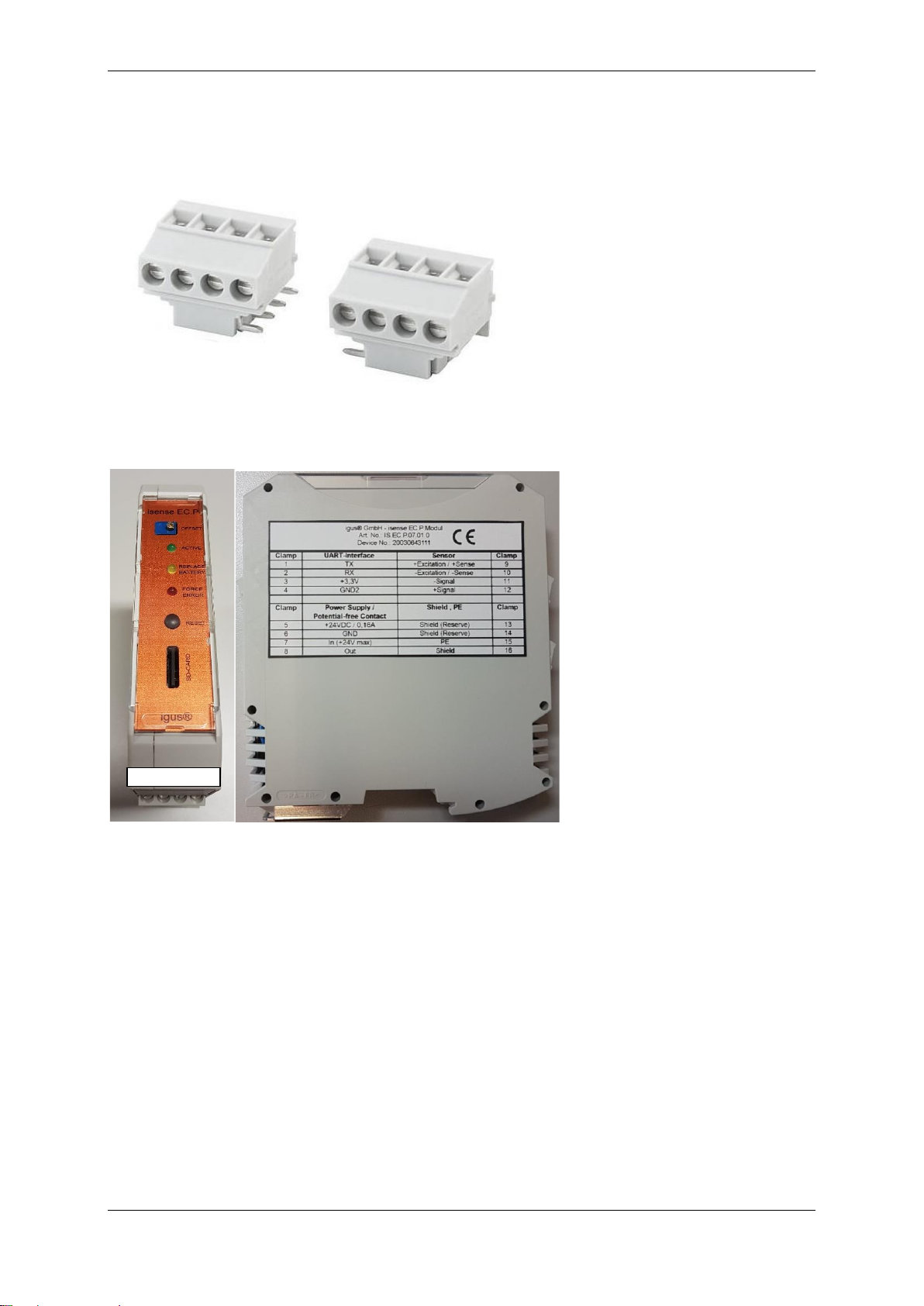
4.2.2 Connector assignment and sensor connection
- Wires with cross sections of 0,15 - 2,5 mm2connectable with screws
- Recommended to use terminal blocks for connecting sensorics, structured wiring is given easier
Connectors of i.Sense EC.P
Housing
i.Sense EC.P housing
1 | 2 | 3 | 4

Installation
9/14
Manual i.Sense EC.P- V 1.1
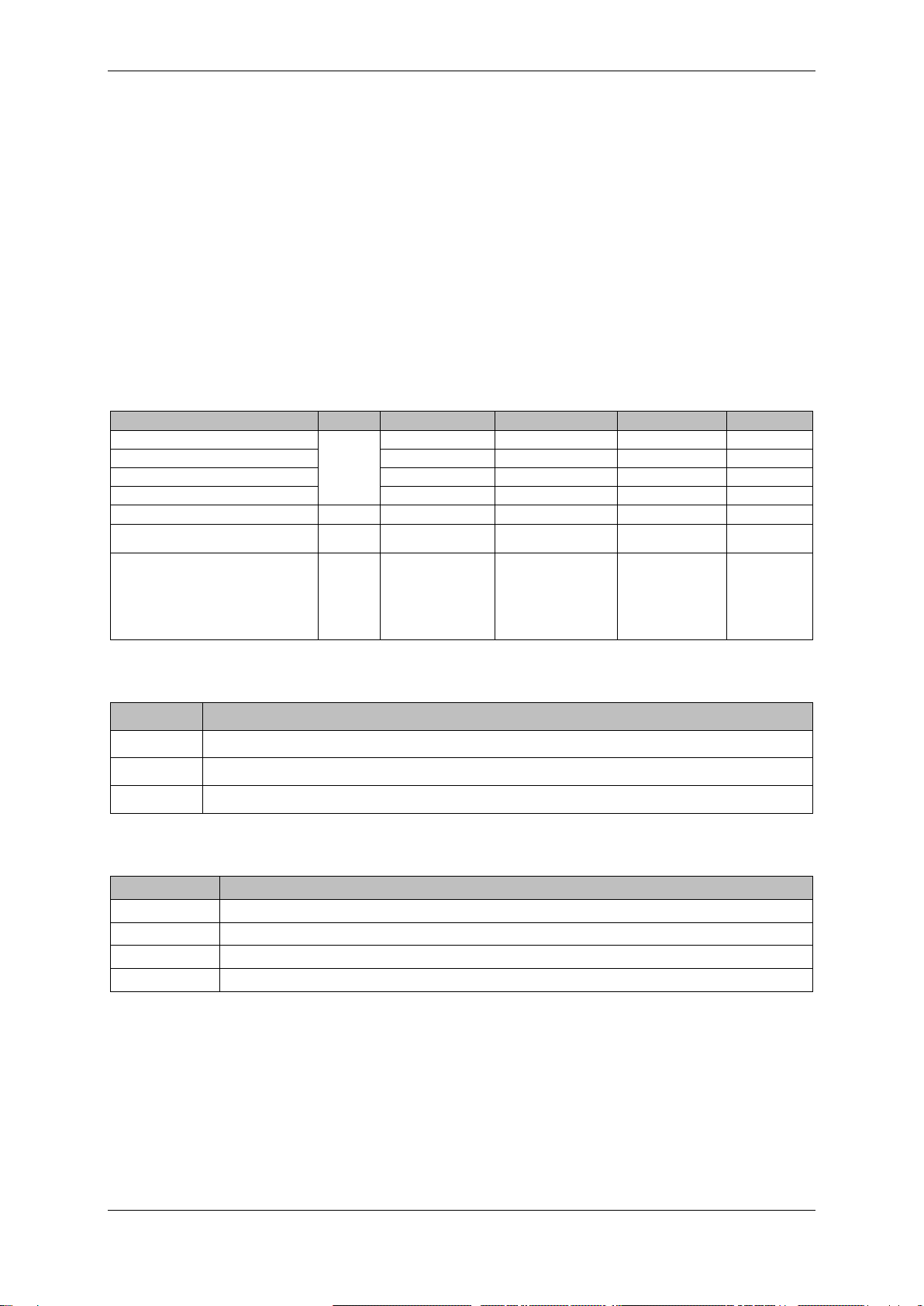
module’s connecting diagram
5
24 V DC/ 0,16 A
1
TX
6
GND
2
RX
7
In (24 V max.)
3
+3,3 V
8
out
4
GND 2
Power Supply & Potential-free contacts
UART- Interface
↑ DIN rail ↑
i.Sense EC.P
Shield & PE
Sensor
13
Shield (Reserve)
9
+ Excitation/+ Sense
14
Shield (Reserve)
10
- Excitation/- Sense
15
PE
11
- Signal
16
Shield
12
+ Signal
Sensor connection
Vishay load cell model 616,1t
Clamp
Name
Colour
9
+Excitation/+Sense
Green/blue
10
-Excitation/-Sense
black/brown
11
-Signal
white
12
+Signal
red
16
Shield
Shield
Vishay load cell model 620,2t
Clamp
Name
Colour
9
+Excitation/+Sense
Green/blue
10
-Excitation/-Sense
Black/grey
11
-Signal
Red
12
+Signal
White
16
Shield
Shield
igus force sensors ( all models with CF10.Ini-cable)
Clamp
Name
Colour
9
+Excitation/+Sense
White
10
-Excitation/-Sense
Black
11
-Signal
Blue
12
+Signal
Brown
16
Shield
Shield
Connecting UART interfaces
Clamp
Name
Colour
1
TX
Yellow
2
RX
Orange
3
+3,3 V
Red
4
GND 2
black

Sensor installation
10/14
Manual i.Sense EC.P- V 1.1
5 Sensor installation
5.1 Configuration
5.1.1 Setting force limits
The configuration of the microprocessor unit is done by adjusting the text files, saved on the SD-card.
There are two files saved:
Config.txt: Is not allowed to be changed.
config.txt
Values.txt:
Here parameters can be assigned to the needed limits, the sequence of numbers is described below. It is recommended to set
the force limits to nominal force of the load cell, can be changed afterwards.
For finishing the configuration, the RESET button must be pushed for five seconds while the device turns on. After that the limits
have been set from values.txt.
For finishing the configuration, the RESET button must be pushed for five seconds while the device turns on. After that
the limits have been set from values.txt.
NOTE!
EC.P.03… load cell capacity, one force limit (only one value for upper and lower limit) and a forcefactor to multiplictae the
measured force has to be set.
values.txt (EC.P.03…)
EC.P.07… additionally there is the possibility to set various outer force limits (under and over zero-point), where alerting takes
place if the value is passed only once. Moreover, an inner force limit can be set in each direction, it is monitored the pass of an
average out of an number of values (adjustable).
values.txt (EC.P.07…)
After that a calibration has to take place.
Without calibration, there are wrong trigger limits. The correct operation is no longer guaranteed and there can be
malfunctions, so that there can be danger for machine and human.
NOTE!

Sensor messages
11/14
Manual i.Sense EC.P- V 1.1
5.1.2 Set date and time
Date and time can be set in values.txt.
5.2 Calibration
- Push and hold RESET button
- Turn offset-potentiometer until yellow LED flashs
- Red LED flashs: force limit too high
- Green LED flashs: force limit too low
- Push RESET button again, calibration finished
Visual shown on p.11 of Assembly instruction.
Offset can also bechanged by terminalprogram, OFFSET potentiometer has to be turned until force is 0 .
6 Sensor messages
The metrics are stored 18 times per minute as CSV-file on SD-card. A new file is generated after eight hours and when turning
on the module. A maximum of 250 files can be stored, before the circular buffer begins again at file, that file will be overwritten.
6.1 String structure
The sensor messages are given in that form:
IS.EC.P.03…
IS.EC.P.07…
If force is out of adjusted limits, no LED blinks. For calibration it is recommended to use load cells nominal force as force
limits. This can be changed afterwards. (see 5.1.1)
NOTE!
Name
Format
Date
DD.MM.JJJJ;
Time
HH:MM:SS;
Upper Force Limit [N]
XXXXXX;
Actual Force [N]
XXXXXX;
Lower Force Limit [N]
XXXXXX;
Name
Format
Date
DD.MM.JJJJ;
Time
HH:MM:SS;
Absolute Upper Force Limit [N]
XXXXXX;
Upper Force Limit [N]
XXXXXX;
Actual Force [N]
XXXXXX;
Lower Force Limit [N]
XXXXXX;
Absolute Lower Force Limit [N]
XXXXXX;
Number of Upper Force Tolerance Oversteppings
XXXXXX;
Number of Lower Force Tolerance Oversteppings
XXXXXX;
Number of Force Sampling until Averaging
XXXXXX;\ r\n

Maintenance / change battery
12/14
Manual i.Sense EC.P- V 1.1
7 LED conditions
LED
(flash)
Description
Condition floating
contact
Green
(Active)
Modul connected to 24V DC and tension in limits
high
Yellow
(replace
battery)
LED turns on if buffer battery is empty. Please change battery, it is described how
to change on page 12 (8 maintenance/ change battery).
Before replacing thebatteries, it is imperative that the device be shutdown
and that you ensure that it has been disconnected from all power.
Otherwise, there is danger of injuries and device malfunction. Use only
batteries with exactly the same characteristic values.
These values are:
Lithium button cell Type CR 1225 3V 50 mAh
CAUTION!
If the battery is to be replaced, the housing must be opened. It is imperative
that you coordinate this effort ahead of time with the responsible igus®
branch to avoid invalidating your guarantee.
Any other procedure voids the guarantee.
NOTE!
Date and time must be reset after changing the battery.
NOTE!
high
Red
(Force
Error)
The maximum movement range is passed.
The pass can be acknowledged by pushing the RESET button, the
measurement will continue.
NOTE!
low
none
The device is separated from power supply.
low
8 Maintenance / change battery
Battery must be changed if yellow LED flashs. Disconnect the device from all power and prove if there is no power anymore. Open
the housing carefully and change the battery by keeping the ESD guidelines.
The specifications of the old and the new battery must be equal.
If hardware problems occur, please contact customer service (p. 14).
It is imperative that the device be completely disconnected from power. Failure to ensure disconnection and follow ESD
measures can result in shock and the destruction of the device.
CAUTION!
After battery replacement, date and time must be reset in setup area.
NOTE!
Wiring diagrams
13/14
Manual i.Sense EC.P- V 1.1
9 Troubleshooting
- The unit does not detect all sensor data. What now?
oCheck all plug-in connections and restart the system.
oIf this does not help, contact the Customer service (p.14)
10 FAQs
- How are the sensor limits set?
oIn file values.txt (SD-card)
oSee chapter 5.1.1 setting force limits (p.10)
- How do you retrieve the sensor data?
oThe determined data are stored on SD-card
11 Accessories
Article
amount
Cable length [m]
Nominal force[N]
Article number
supplier
Force sensor (little)
1
5
X
ISENSE
Igus®
Force sensor (big)
5
X
ISENSE
Igus®
Vishay load cell 616, 1t
3
10.000
MAT01722742
Igus®
Vishay load cell 620, 2t
5
20.000
MAT01722743
Igus®
Beam for mounting carrying run
1
/
/
/
customer
Chainflex-cable with assembled
M12 connector
1
Customer’s
specification
/
/
Igus®
screws (sorted by e-chain®):
E4.32: M5x20
E4.42: M6x20
E4.56: M8x20
P4: M10x20
8
/
/
/
customer
12 Abbreviations
Abbreviation
Description
EMC
Elektromagnetic compatibility
ESD
Electrostatic discharge
PLC
Programmable Logic Controller
13 Explanation of terms
Term
Description
Force Factor
Factor, the measured force is multiplied with (lever)
Force limit
Limit, that a a measured force should not pass
Outer force limit
Passing this limit once triggers the sensor
Inner force limit
Passing this limit several times in a litthle while triggers the sensor (parameters are defined in values.txt)
14 Wiring diagrams
Inserted after page 14.

Service
14/14
Manual i.Sense EC.P- V 1.1
15 Service
Customer service
de-smartplastics-serv[email protected]
+49 (0) 2203 9649 9806
Technical support for igus®smart plastics
Documentation/FW
https://www.igus.de/info/zustandsueberwachung-ec-p
Download of manuals, FW updates and certificates
Website smart Plastics
https://www.igus.de/info/vorausschauende-wartung-smart-plastics
Possibility to order sensors, processing units and other accessories
Contact
www.igus.com
+49 (0) 2203-9649-0F
Legal Notice
© 2021
All rights reserved by
igus®GmbH
Spicher Str. 1a
D-51147 Cologne


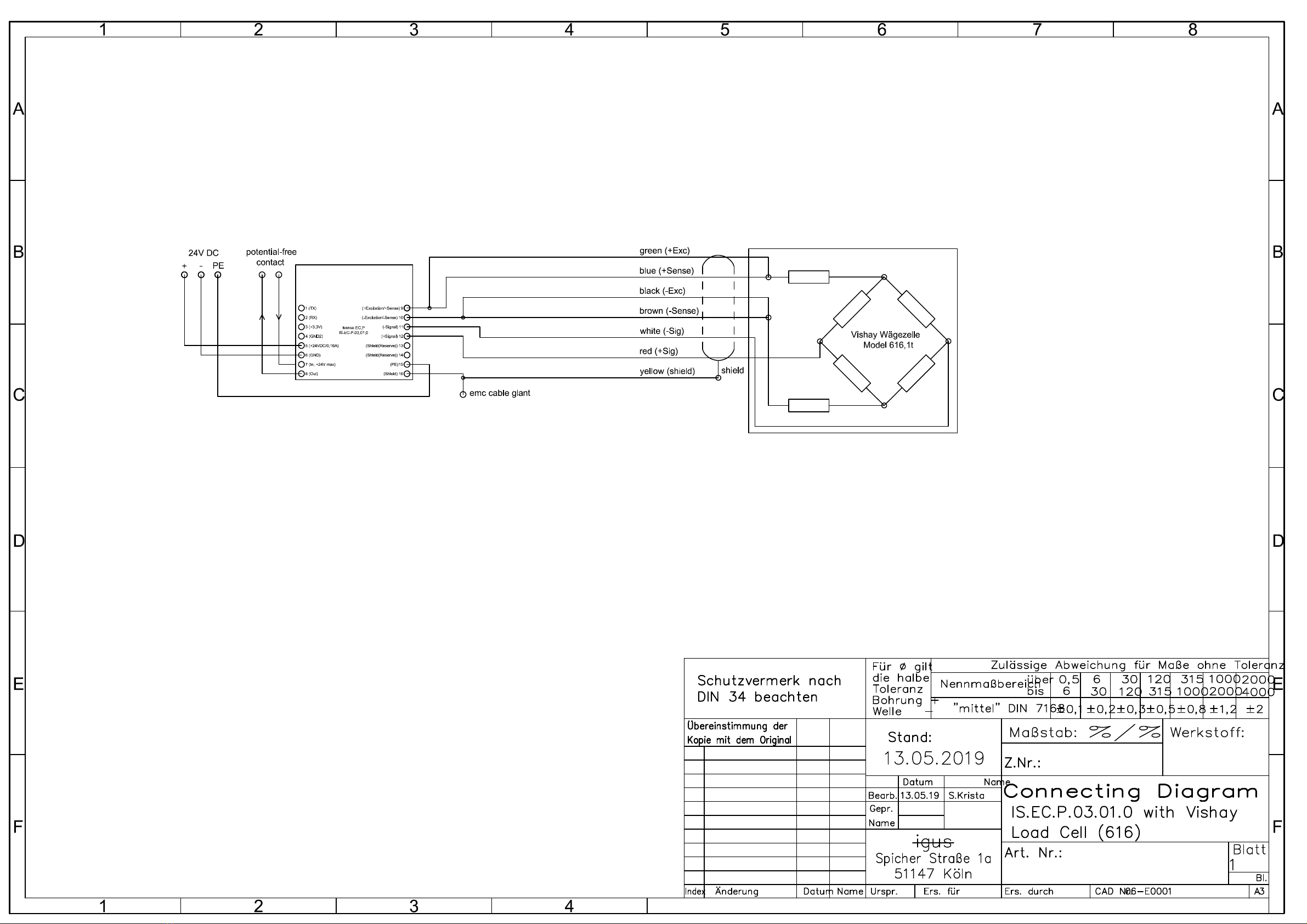

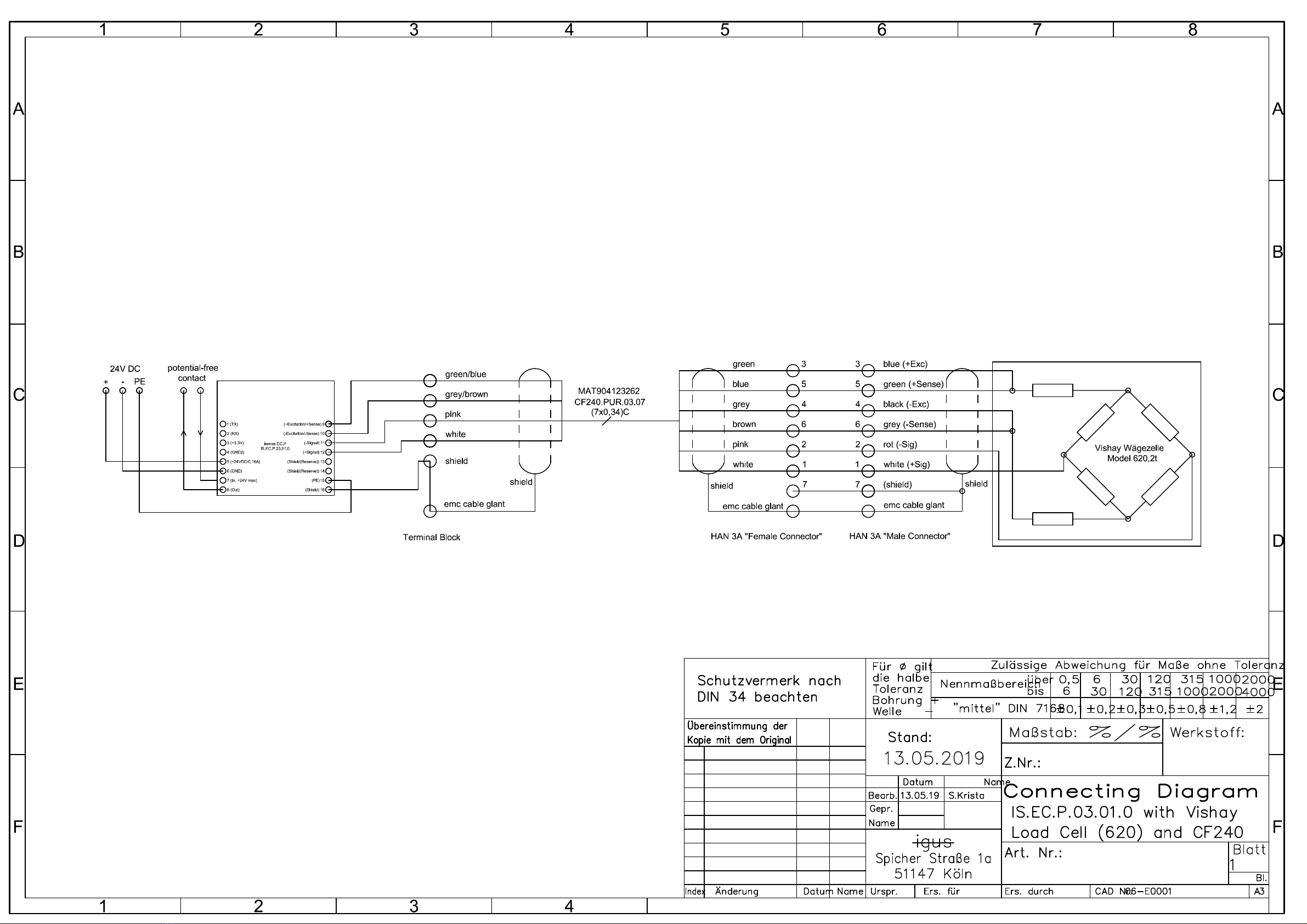

Table of contents
Other igus Industrial Equipment manuals


