manuals.online logo
Brands
  1. Home
  2. •
  3. Brands
  4. •
  5. SMC Networks
  6. •
  7. Industrial Equipment
  8. •
  9. SMC Networks EX510-DYN3 User manual

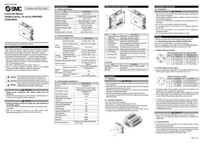
SMC Networks EX510-DYN3 User manual

EX510-TF2Z142EN
Page 1 of 2
Instruction Manual
Fieldbus system - Output unit
EX510-DY#3 / -DY#4
The intended use of this product is to provide outputs to control
pneumatic valves and I/O while connected to an SI or Gateway unit.
1 Safety Instructions
These safety instructions are intended to prevent hazardous situations
and/or equipment damage. These instructions indicate the level of
potential hazard with the labels of “Caution,” “Warning” or “Danger.”
They are all important notes for safety and must be followed in addition
to International Standards (ISO/IEC)*1), and other safety regulations.
*1) ISO 4414: Pneumatic fluid power - General rules relating to systems.
ISO 4413: Hydraulic fluid power - General rules relating to systems.
IEC 60204-1: Safety of machinery - Electrical equipment of machines.
(Part 1: General requirements)
ISO 10218-1: Manipulating industrial robots -Safety. etc.
•Refer to product catalogue, Operation Manual and Handling
Precautions for SMC Products for additional information.
•Keep this manual in a safe place for future reference.
Caution
Caution indicates a hazard with a low level of risk which, if
not avoided, could result in minor or moderate injury.
Warning
Warning indicates a hazard with a medium level of risk
which, if not avoided, could result in death or serious injury.
Danger
Danger indicates a hazard with a high level of risk which, if
not avoided, will result in death or serious injury.
Warning
•Always ensure compliance with relevant safety laws and
standards.
•All work must be carried out in a safe manner by a qualified person in
compliance with applicable national regulations.
•Refer to the operation manual on the SMC website (URL:
https://www.smcworld.com) for further Safety Instructions.
2 Specifications
2.1 General specifications
Item
Specifications
Enclosure rating
IP20
Withstand voltage
500 VAC for 1 minute
(between FG and terminal block)
Insulation resistance
10 MΩor more 500 VDC
(between FG and terminal block)
Ambient temperature
Operating: -10 to +50 oC
Storage: -20 to +60
o
C
Ambient humidity
35 to 85% RH (no condensation)
Operating atmosphere
No corrosive gas
Weight
130 g (including accessories)
2 Specifications (continued)
2.2 Output unit specifications
Item
Specification
Model
EX510-
DYN3
EX510-
DYP3
EX510-
DYN4
EX510-
DYP4
Output type NPN / sink
(positive
common)
PNP /
source
(negative
common)
NPN / sink
(positive
common)
PNP /
source
(negative
common)
Number of outputs
16 outputs
Rated Load
Voltage
24 VDC
Power supply type Internal power supply
(from GW unit)
External power supply
(from power supply
connector)
Power supply
connector wire size
-
0.14 to 1.5 mm2
(AWG26 to 16)
Output connector
Cage clamp type (WAGO 739-304 / 310)
Output wire size
0.08 to 1.5 mm2(AWG28 to 16)
Maximum Load
current
To meet the following 3
conditions:
1) 1 output: 0.5 A max.
2) 1 unit: 1 A max.
3) Total current of
OUT0 - 7: 1 A max.
OUT8 - 15: 1 A max.
To meet the following
3 conditions:
1) 1 output: 0.5 A max.
2) 1 unit: 3 A max.
3) Total current of
OUT0 - 7: 1.5 A max.
OUT8 - 15: 1.5 A max.
Protection
Short circuit protection
Current
consumption
50 mA max. (output unit circuit)
3 Name and function of parts
No Part Description
1 Branch connector Connection for branch cable to GW unit.
2
Output terminals
Connection for output loads.
3 Power supply LED
LED ON: Power ON (normal)
LED OFF: Power OFF
4 Communication LED
LED ON: Receiving data
LED OFF: No data received
5 Display LED
LED ON: Output signal ON
LED OFF: Output signal OFF
6 Fuse Replaceable fuse.
7 Mounting slot Used for mounting on DIN rail.
8 Mounting hole Used for direct mounting with M4 screws.
9 Cover
Cover to protect cables and provide label
marking.
10
Power supply
terminals
Connection for external power supply
(EX510-DYN4, -DYP4).
11 Branch connector Connector for branch cable (2 pcs.)
12 Marker plate Label marking for output details.
4 Installation
4.1 Installation Warning
Do not install the product unless the safety instructions have been read
and understood.
•Direct mounting
Install the output unit using 2 x M4 screws.
Tightening torque: 0.8 N•m.
•DIN rail mounting
To mount the product hook claw 1 under the lower side and claw 2
over the upper side of the DIN rail. Press down until it clicks.
To remove from the DIN rail, push up the DIN rail fixing plate with a
flat blade screwdriver, and remove by tilting claw 2 forward.
4.2 Environment Warning
•Do not use in an environment where corrosive gases, chemicals, salt
water or steam are present.
•Do not use in an explosive atmosphere.
•Do not expose to direct sunlight. Use a suitable protective cover.
•Do not install in a location subject to vibration or impact in excess of
the product specifications.
•Do not mount in a location exposed to radiant heat that would result
in temperatures in excess of the product specifications.
5 Wiring
5.1 Branch cable wiring
The wiring between the Output unit and GW unit uses a branch cable
(EX510-FC##) and branch connector (EX510-LC1). The Output unit has
2 branch connectors.
5.1.1 Pressure welding the branch connector
The pressure welding assembly method of the branch connector is
described below.
•Assembly procedure
1) Set a branch cable into the cover with the Brown wire to pin #1.
2) Push the cable end up to the insulating cap on the cover.
3) Fold the cover so that the branch cable is trapped between the cover.
4) Fix the latch tip by inserting it through the fixing latch hole.
5) Check that the wire colour marked on the branch connector is the
same as the branch cable wire colour.
•Cable clamping
1) Tentatively fix the Body. Fit the 4 latches on the body to the 4
ditches in the cover and press them until the latch engages.
2) Press fit the cover to the body using suitable pliers.
3) Check that all of the 4 latches are fully engaged.
DIN rail
fixing plate
Latch
Hole for
fixing latch
Pin #1
Brown wire
Insulating cap
Pin number
Cover
Body
Branch Connector
Branch Cable (EX510-FC##)
•Components
ORIGINAL INSTRUCTIONS
Top view
(with cover removed)
EX510-TF2Z142EN
Page 2 of 2
5 Wiring (continued)
5.2 Internal Circuit and Wiring
5.2.1 EX510-DYN3: NPN output (internal GW power supply)
5.2.2 EX510-DYN4: NPN output (external power supply)
5 Wiring (continued)
5.2.3 EX510-DYP3: PNP output (internal GW power supply)
5.2.4 EX510-DYP4: PNP output (external power supply)
5 Wiring (continued)
5.3 Connection of Branch cable and Output wiring
1) Insert the branch cable into the socket on the Output unit.
2) Insert the output wiring after removing the cover as follows:
• Insert a flat blade screwdriver into the slot in the terminal block
connector to the end position.
• Hold the terminal wire clamp open using the blade of the
screwdriver.
• Insert a wire into the wire entry of the terminal block and pull the
screwdriver out to finish.
• Stripping the output wire too long might expose a conductor and
cause insulation failure, and too short may trap the sheath causing
the conductor to be unclamped or clamped improperly, resulting in
contact failure or disconnection of the wire.
• The flat blade screwdriver should have a 2.5 mm x 0.4 mm blade end
width to hold the clamp open.
•
6 How to Order
Refer to the operation manual on the SMC website (URL:
https://www.smcworld.com) for How to order information.
7 Outline Dimensions (mm)
Refer to the operation manual on the SMC website (URL:
https://www.smcworld.com) for outline dimensions.
8 Limitations of Use
8.1 Limited warranty and Disclaimer/Compliance Requirements
Refer to Handling Precautions for SMC Products.
9 Product disposal
This product should not be disposed of as municipal waste. Check your
local regulations and guidelines to dispose of this product correctly, in
order to reduce the impact on human health and the environment.
10 Maintenance
10.1 General Maintenance Caution
•Not following proper maintenance procedures could cause the
product to malfunction and lead to equipment damage.
•If handled improperly, compressed air can be dangerous.
•Maintenance of pneumatic systems should be performed only by
qualified personnel.
•Before performing maintenance, turn off the power supply and be
sure to cut off the supply pressure. Confirm that the air is released to
atmosphere.
•After installation and maintenance, apply operating pressure and
power to the equipment and perform appropriate functional and
leakage tests to make sure the equipment is installed correctly.
•If any electrical connections are disturbed during maintenance,
ensure they are reconnected correctly and safety checks are carried
out as required to ensure continued compliance with applicable
national regulations.
•Do not make any modification to the product.
•Do not disassemble the product, unless required by installation or
maintenance instructions
•Stop operation if the product does not function correctly.
11 Contacts
Refer to www.smcworld.com or www.smc.eu for your local distributor /
importer.
URL: https://www.smcworld.com (Global) https://www.smc.eu (Europe)
SMC Corporation, 4-14-1, Sotokanda, Chiyoda-ku, Tokyo 101-0021, Japan
Specifications are subject to change without prior notice from the manufacturer.
© 2021 SMC Corporation All Rights Reserved.
Template DKP50047-F-085M
Branch Connector
Branch
Connector
Branch connector
To GW unit
Branch connector
on Output unit
Branch cable
External power
supply Connector
Branch Connector
External power
supply Connector
Branch
Connector
Output Terminal wiring
• Applicable wire size: 0.08 to 1.5mm2
(AWG 28 to 16).
• Wire sheath stripped length: 5 to 6 mm.

This manual suits for next models

5

Other SMC Networks Industrial Equipment manuals

SMC Networks CS1 N125 Series User manual

SMC Networks

SMC Networks CS1 N125 Series User manual

SMC Networks AS1000 User manual

SMC Networks

SMC Networks AS1000 User manual

SMC Networks SYJ3000 User manual

SMC Networks

SMC Networks SYJ3000 User manual

SMC Networks JMHZ2-16D-X7400B-CRX User manual

SMC Networks

SMC Networks JMHZ2-16D-X7400B-CRX User manual

SMC Networks KFG2 Series User manual

SMC Networks

SMC Networks KFG2 Series User manual

SMC Networks ZSE20C Series User manual

SMC Networks

SMC Networks ZSE20C Series User manual

SMC Networks MWB Series User manual

SMC Networks

SMC Networks MWB Series User manual

SMC Networks XT316-30(B) User manual

SMC Networks

SMC Networks XT316-30(B) User manual

SMC Networks HF2A-ASG V Series User manual

SMC Networks

SMC Networks HF2A-ASG V Series User manual

SMC Networks ZXP7 41-X1 Series User manual

SMC Networks

SMC Networks ZXP7 41-X1 Series User manual

SMC Networks HEBC002-WA10 User manual

SMC Networks

SMC Networks HEBC002-WA10 User manual

SMC Networks FHIAF-10-M G Series User manual

SMC Networks

SMC Networks FHIAF-10-M G Series User manual

SMC Networks MWB-X3075 Series User manual

SMC Networks

SMC Networks MWB-X3075 Series User manual

SMC Networks MSZ Series User manual

SMC Networks

SMC Networks MSZ Series User manual

SMC Networks ZSE50F User manual

SMC Networks

SMC Networks ZSE50F User manual

SMC Networks EX260-SEN1-X242 User manual

SMC Networks

SMC Networks EX260-SEN1-X242 User manual

SMC Networks CY3R Series User manual

SMC Networks

SMC Networks CY3R Series User manual

SMC Networks 55 Series User manual

SMC Networks

SMC Networks 55 Series User manual

SMC Networks MGC Seires User manual

SMC Networks

SMC Networks MGC Seires User manual

SMC Networks 55-CDU25 DCW3726W User manual

SMC Networks

SMC Networks 55-CDU25 DCW3726W User manual

SMC Networks KFG2-F Series User manual

SMC Networks

SMC Networks KFG2-F Series User manual

SMC Networks JSXFE Series User manual

SMC Networks

SMC Networks JSXFE Series User manual

SMC Networks EX600-SEN5 16 Series User manual

SMC Networks

SMC Networks EX600-SEN5 16 Series User manual

SMC Networks JMHZ2-16D-X7500AC-KA Series User manual

SMC Networks

SMC Networks JMHZ2-16D-X7500AC-KA Series User manual

Popular Industrial Equipment manuals by other brands

ABB HT842982 Operation manual

ABB

ABB HT842982 Operation manual

turck IO-Link Master V1.1 Instructions for use

turck

turck IO-Link Master V1.1 Instructions for use

Belanger 1MANUL603 owner's manual

Belanger

Belanger 1MANUL603 owner's manual

GRAVEDA GRASPRESSO GP50-15 instruction manual

GRAVEDA

GRAVEDA GRASPRESSO GP50-15 instruction manual

Durlum LOOP TYPE 3 installation manual

Durlum

Durlum LOOP TYPE 3 installation manual

M-system M5XADS instruction manual

M-system

M-system M5XADS instruction manual

Lennox EL195UHNE Series manual

Lennox

Lennox EL195UHNE Series manual

Master FVS25E Operation manual

Master

Master FVS25E Operation manual

Arrowquip Q-POWER 106 SERIES product manual

Arrowquip

Arrowquip Q-POWER 106 SERIES product manual

Sic Marking ec7 user guide

Sic Marking

Sic Marking ec7 user guide

entegris SB300 FOSB user manual

entegris

entegris SB300 FOSB user manual

Horizon Fitness SQ3TS Operational manual

Horizon Fitness

Horizon Fitness SQ3TS Operational manual

Pentair CodeLine 40E60 user guide

Pentair

Pentair CodeLine 40E60 user guide

CNC Router Parts PRO 4824 Series Assembly instructions

CNC Router Parts

CNC Router Parts PRO 4824 Series Assembly instructions

Komatsu BR380JG-1E0 Shop Manual

Komatsu

Komatsu BR380JG-1E0 Shop Manual

JAGER F100-H636.01 K0,5RW2V manual

JAGER

JAGER F100-H636.01 K0,5RW2V manual

BRUEL & KJAER 3207 user manual

BRUEL & KJAER

BRUEL & KJAER 3207 user manual

ABB HT567640 Operation manual

ABB

ABB HT567640 Operation manual

manuals.online logo
manuals.online logoBrands
  • About & Mission
  • Contact us
  • Privacy Policy
  • Terms and Conditions

Copyright 2025 Manuals.Online. All Rights Reserved.