Ijinus LOG03V3-3G User manual

Installation guide
LOG03V3-3G: Wireless 3G data logger
2x analog inputs (4-20mA), 2x digital inputs (1 or 0), 1x voltage input (7Vcc...30V)
1x open collector output, 1x voltage output (7Vcc...30V)

Quick programming using Avelour
Installation guide K0J00121
IJINUS - 25 ZA de Kervidanou 3, 29300 MELLAC - France - – Customer Service: +33 2 98 09 03 32 / sav@ijinus.com
2
SUMMARY
1 Introduction ....................................................................................................................................................................3
2 Equipment.......................................................................................................................................................................3
3 Configuration of the logger using the software Avelour ................................................................................................3
3.1 Necessary equipment .............................................................................................................................................4
3.2 Run Avelour and connect to the sensor to configure.............................................................................................5
3.3 General information and name of the logger.........................................................................................................6
3.4 Application: 4-20 mA measure ...............................................................................................................................7
3.5 Data sending by cellular communication .............................................................................................................12
3.6 Local data reading in real time and data download .............................................................................................15
3.7 Data export ...........................................................................................................................................................16
4 Maintenance.................................................................................................................................................................17
4.1 External antenna connection................................................................................................................................17
4.2 Setting up a Sim card ............................................................................................................................................17
4.3 Battery removal ....................................................................................................................................................18
5 Revision of the document.............................................................................................................................................20

Quick programming using Avelour
Installation guide K0J00121
IJINUS - 25 ZA de Kervidanou 3, 29300 MELLAC - France - – Customer Service: +33 2 98 09 03 32 / sav@ijinus.com
3
1Introduction
The logger is autonomous, and battery powered (long-life lithium battery), it logs the data of the connected
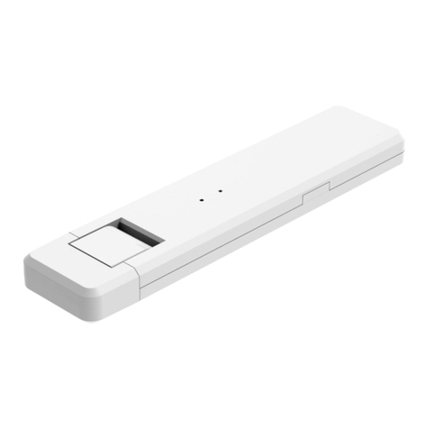
equipment. A mobile programming kit (M0C00001) or Wijikey (WIJIKEY-8) is used to connect on-site by radio (Wiji
protocol) to the logger, to configure it and to retrieve locally the data. Depending on the data logger model, it can
have a modem allowing to automatically send data remotely to the web platform ijitrack.com, or to a client server.
2Equipment
Data logger with its Non rechargeable lithium Programming kits
GSM antennabattery 3.6V 34Ah
External antenna Bracket Extension cable with
(option) bare wire ends
First, connect the battery (details in chapter 4.3) and insert the sim card (beveled side-up, details in chapter
4.2) on its holder.
3Configuration of the logger using the software Avelour

Quick programming using Avelour
Installation guide K0J00121
IJINUS - 25 ZA de Kervidanou 3, 29300 MELLAC - France - – Customer Service: +33 2 98 09 03 32 / sav@ijinus.com
4
3.1 Necessary equipment
- The software Avelour in 6.7 version minimum
- Programing Wiji kit (with its cable and antenna) or Wiji key (USB/HF stick)
Software Avelour 6
Programming kit
Wiji Key (USB stick with RFID)
- The data logger LOG03V3 must be connected to the equipment using the provided cable. Wiring information
are presented below:
Male: Female:
Cable color
White
Brown
Green
Yellow
Grey
Pink
Blue
Red
Connector 8Pts
1
2
3
4
5
6
7
8
Signal Vin GND Vout Input Input Input Input
Output
Open drain
(2A/30V)
Type 7V...30Vdc Ground 7...30Vdc Current 1 Current 2 Digital 1 Digital 2
Grounding
contact
Feature Power in Switch 4-20 mA 4-20 mA 1 or 0 1 or 0
Open drain
(1A/30V)
The output voltage of pin 3 can either comes directly from the input voltage using the internal switch or generated
by the logger from the internal power, this setting can be done using Avelour software. When using the internal
generator, the output voltage can be set using DIP switches. Below is the table of possible output voltage. the
default setting is 8,8V. If a different power supply is needed for the external sensor, it is possible to change
manually the switch code located on the bottom daughter board of the logger.

Quick programming using Avelour
Installation guide K0J00121
IJINUS - 25 ZA de Kervidanou 3, 29300 MELLAC - France - – Customer Service: +33 2 98 09 03 32 / sav@ijinus.com
5
3.2 Run Avelour and connect to the sensor to configure
After connection of the Wiji kit equipped with its antenna (or the Wiji key) on the laptop or PC USB port, run the
software Avelour.
NB: at least 1 meter distance is needed between the Wiji antenna and the datalogger for a correct radio
connection.
Click the button “Connect to a wireless device” then the sensor or logger will be directly visible by its part number
(SN) without the need to activate anything else on the device. Locate the sensor's serial number (SN) on the sensor
label (ex: IJA0101-0000 3559) and on the connection screen and click "OK".
On the first connection with the sensor only the serial number will appear. The full name of the installation site
will appear at the next connections.
Selection of the logger to configure
During its connection with the logger, the following pop up appears:
When connected, and only if the sensor already has measures in memory, the following options will suggest
retrieving the measures:
After choosing one of these options, if the sensor is not up to date (case of new firmware developed in a new
version of the software Avelour since the last connection). It is strongly recommended to read carefully the
different messages in the options windows.

Quick programming using Avelour
Installation guide K0J00121
IJINUS - 25 ZA de Kervidanou 3, 29300 MELLAC - France - – Customer Service: +33 2 98 09 03 32 / sav@ijinus.com
6
The firmware update process can last a moment. On-site prefer the best radio connection (so not if the metal
cover of a manhole is closed).
When the logger has finished these checks, Avelour will look bellow figure:
3.3 General information and name of the logger
This part is useful to describe the measurement point.
The most important information would be the name that will help to find the sensor at a future connection.

Quick programming using Avelour
Installation guide K0J00121
IJINUS - 25 ZA de Kervidanou 3, 29300 MELLAC - France - – Customer Service: +33 2 98 09 03 32 / sav@ijinus.com
7
3.4 Application: 4-20 mA measure
To set the logger, it is necessary to choose one or several applications, and then define the desired configuration.
Several applications are available with the LOG03V3, using 4-20 mA and / or Modbus input and /or open-drain
output.
This chapter describes the configuration of the sensor. First, select in the "Add menu" the application “4-20mA
measure"
The configuration table while the template is selected is as follow:
Choice of the Measuring period
In this menu, please select the desired measuring frequency (in this example every 5 minutes).
At the right of the Measure period selector are 2 icons allowing to choose a different measuring frequency based
on specific days of the week and/or time.

Quick programming using Avelour
Installation guide K0J00121
IJINUS - 25 ZA de Kervidanou 3, 29300 MELLAC - France - – Customer Service: +33 2 98 09 03 32 / sav@ijinus.com
8
Choice of the duration of supply of the probe
If the 4-20 mA probe is to be powered, a duration should be set according to the needs of the probe. By default,
the duration is set at 25 ms which corresponds to the need of the pressure probes provided by Ijinus. For example,
for the inclinometer provided by Ijinus, the duration must be set to 500ms.
Setting the 4-20mA signal conversion:
- Peripheral: Choose: « 4-20mA input by default (wiring pins 4,3,2 = i, V+, GND)
- Conversion: Click on the « Off » button to display the green « On » and be able to do the conversion of
the 4-20 mA signal into one of the five possible units: water height (mm), pressure (bar), temperature
(°C), angle (°) or quantify without unit.
For each of the five units, four parameters could be set:
1. Value at 4mA: the minimum value (in most cases 0) of the sensor connected to the logger
2. Value at 20mA: the maximum value of the sensor connected to the logger
3. Offset on conversion: to define if needed for the measure
4. Set a threshold: It is possible to define a threshold like the following example.
This threshold is based on the Channel 1 conversion and “Rising edge” but you may choose “Falling edge”
for the direction if it is more relevant for your application. The Delay can also be set on activation and/or
deactivation.
An acceleration of the measured frequency is an option you can choose. Define it as active and enter the
new value.
If the data logger has a modem, it is possible to activate an “Anticipated data sending”. It would be based
on the activation and/or deactivation of the threshold.
An output activation is also possible with the activation of the threshold by using the open-drain output.

Quick programming using Avelour
Installation guide K0J00121
IJINUS - 25 ZA de Kervidanou 3, 29300 MELLAC - France - – Customer Service: +33 2 98 09 03 32 / sav@ijinus.com
9
If the current is converted in water height, three more parameters can be set:
1. Calibration:a calibration of the connected sensor is possible to put an offset on the converted height
measurement
2. Flowrate / Volume: it is possible to convert the height measurement into a flowrate measurement. To
calculate the flowrate, a relationship between the water height and the flowrate must be indicated in the
logger. To do so, a table should be created by clicking in the "Edit table" button to have the possibility to
create the table by clicking on the "Edit table" button.
With the flowrate, two calculation of the volume accumulation can be done and recorded in the logger:
periodic (hourly, daily or monthly) and/or infinite.
3. Sampler enslaving: If the flowrate calculation has been set, it is possible to enslave a sampler with the
open-drain output. The enslaving volume can be adjusted and a verification of the good relationship
between the logger and the sampler can be verified by clicking on the "Launch" button.
Five enslaving conditions are available: none, height over a high level threshold (mm), height under a low
level threshold (mm), flow over a high level threshold (m3/s), flow under a low level threshold (m3/s).

Quick programming using Avelour
Installation guide K0J00121
IJINUS - 25 ZA de Kervidanou 3, 29300 MELLAC - France - – Customer Service: +33 2 98 09 03 32 / sav@ijinus.com
10
Advanced parameters
The “View advanced parameters“ button allows more functionalities:
Displaying the configuration summary
Once the configuration is complete, a summary synthesizes the preferences. To change the preferences, click the
“Edit” button.

Quick programming using Avelour
Installation guide K0J00121
IJINUS - 25 ZA de Kervidanou 3, 29300 MELLAC - France - – Customer Service: +33 2 98 09 03 32 / sav@ijinus.com
11
Saving the configuration
You must save the configuration by clicking on the “Program the device” button, to send it to the logger’s
memory.
After few seconds, a pop-up window appears to indicate that the configuration has been saved successfully in
the logger.

Quick programming using Avelour
Installation guide K0J00121
IJINUS - 25 ZA de Kervidanou 3, 29300 MELLAC - France - – Customer Service: +33 2 98 09 03 32 / sav@ijinus.com
12
3.5 Data sending by cellular communication
As explain at the beginning of the document, different ways to send data are possible like SMS and FTP transfer
using 2G or 3G connection. This chapter explains the way to do it by FTP.
First,if no operator signal is available in surface on the installation location, it will be even more difficult through
a metal cover in the manhole.
Second:
- Insert in the logger sim holder a regular size data sim card with at least 5Mbytes data/month on your plan.
While buying the Sim card please ask the APN of the operator, as well as the Pin code if there is any. This
information will be needed. The cellular antenna has also to be connected to the connector on top of the logger.
- Set now the time zone in the System options menu:
- After clicking the Edit button, choose the sending period, define to send every day or only some of them. It is
possible to define several periods by clicking on the green + icon. Depending on the needed configuration, choose
a minimum delay between 2 anticipated data sending.

Quick programming using Avelour
Installation guide K0J00121
IJINUS - 25 ZA de Kervidanou 3, 29300 MELLAC - France - – Customer Service: +33 2 98 09 03 32 / sav@ijinus.com
13
- If the Sim card id is locked, please enter the code and press the Inactive button (that will turn green and become
Active) and Program the pin code button.
- Enter the APN code and press the Program APN button. A message will confirm the success for each operation.
By default, the parameters are set to send the data to our server as we propose a web platform ijitrack.com with
different services to manage them. So, if this option is selected, no change is needed in the FTP Username.
Before forcing a data sending, click on “Program the device” button to send the configuration in the logger
memory.
At this stage it is possible to run a sending test by pressing the "Force data retrieval"button and check on
ijitrack.com if the sensors data appears.
If your account is not already created, please ask to the customer service to do it.
The "modem diagnostic" button, available on the modem configuration, allows a better diagnosis of the 2G / 3G
reception by doing multiple measurements.

Quick programming using Avelour
Installation guide K0J00121
IJINUS - 25 ZA de Kervidanou 3, 29300 MELLAC - France - – Customer Service: +33 2 98 09 03 32 / sav@ijinus.com
14
In the advanced mode, it is possible to do continuous modem measurements on a longer period. These options
are practical to know on which side of the manhole the antenna should be placed, before drilling in the concrete
under the cover plate and inserting it.
RSSI information: Usual values are:
RSSI > -90 dBm: Very good
RSSI between - 90 up to -105 dBm: Acceptable
RSSI < - 105 dB: No network
While testing the network, some special values could appear: -1 or 0, meaning no network available for
communication.
Advanced parameters
If you need to send the data to your server, first click the “View advanced parameters”, then the FTP / internet
Options will appear as the PPP options in the modem options. You need to fill in your own information details
regarding your server access. Your server administrator can provide to you this information.
After completing this chapter please press the Program the devise button, the configuration will be sent by
radio to the sensor.

Quick programming using Avelour
Installation guide K0J00121
IJINUS - 25 ZA de Kervidanou 3, 29300 MELLAC - France - – Customer Service: +33 2 98 09 03 32 / sav@ijinus.com
15
3.6 Local data reading in real time and data download
You Have few possibilities to read the data in real time: By pressing the “Test measure” button,
or by selecting on the main menu the window “View broadcast measures”
(Main menu > Windows > View broadcast measures)
View broadcast measures: this option opens a window showing the measures received by radio from Ijinus
sensors and loggers nearby.
If you want to download the data locally if your logger is programmed with FTP transfer, you need to use:
Menu > Actions > Auxiliary Measures (for SMS) > Retrieve measures.
You can view the data, even offline, on graphic and list. A graph configuration module allows you to change colors,
thickness of lines, …, but also to apply statistical filters and formula to your data.

Quick programming using Avelour
Installation guide K0J00121
IJINUS - 25 ZA de Kervidanou 3, 29300 MELLAC - France - – Customer Service: +33 2 98 09 03 32 / sav@ijinus.com
16
3.7 Data export
From the graph and/or list of data you find the tab “Export the measures” with the choice of different files format
and style of reports, from date to date, by month, or simply all data.

Quick programming using Avelour
Installation guide K0J00121
IJINUS - 25 ZA de Kervidanou 3, 29300 MELLAC - France - – Customer Service: +33 2 98 09 03 32 / sav@ijinus.com
17
4Maintenance
4.1 External antenna connection
Use only an external antenna provide by Ijinus.
Three lengths are available as standard: 1, 3 or 5m. In exceptional cases a length
of 10m can be proposed. Antennas are suitable for sewer network applications
with thick cable and reinforced sealing.
Important: The antenna should be connected to the sensor by screwing it completely to ensure a good seal.
Identify the best antenna installation conditions, including the drilling direction for the best quality of
communication. A positioning and data sending test is available from the Avelour 6 software (described in section
3.6 of this document "sending data in GPRS"). This test is to be done before and after installation (closed manhole
cover).
4.2 Setting up a Sim card
Our sensors and loggers contain components that can be damaged by electrostatic discharge. Unload the body of
electrical charges before opening and handling the device.
Our sensors and recorders with integrated GSM / GPRS / 3G modem need a SIM card to work.
The following steps must be followed to ensure the correct operation of the sensor:
- The sensor must not be in radio communication with the software or connected via USB, in order to recognize
the SIM card.
- Unscrew the protective ring and remove the cover.

Quick programming using Avelour
Installation guide K0J00121
IJINUS - 25 ZA de Kervidanou 3, 29300 MELLAC - France - – Customer Service: +33 2 98 09 03 32 / sav@ijinus.com
18
- Take care not to leave the sensor open for too long (max 2 min) to avoid that the desiccant bags absorb too
much moisture.
- Insert the Sim card (beveled edge facing up).
- To close the cover, place the cover on the body of the sensor by locating with the key and screw the clamping
ring at the end
4.3 Battery removal
- Unscrew the clamping ring and remove the cover.
- Remove the battery from its housing and disconnect it.
- Change desiccant bags if they are green.

Quick programming using Avelour
Installation guide K0J00121
IJINUS - 25 ZA de Kervidanou 3, 29300 MELLAC - France - – Customer Service: +33 2 98 09 03 32 / sav@ijinus.com
19
- Connect the new battery and push the button to restart the sensor. When restarting, the LED should flash Red
/ Green, then only one green flash every 10 seconds.
- Insert the new battery into the logger and insert the new desiccant bags on the side of the battery. Place the
cover on the body of the sensor by locating with the key and screw back the clamping ring.

Quick programming using Avelour
Installation guide K0J00121
IJINUS - 25 ZA de Kervidanou 3, 29300 MELLAC - France - – Customer Service: +33 2 98 09 03 32 / sav@ijinus.com
20
5Revision of the document
Date
Revision
Writer(s)
Modifications
03/07/2019 2A03
D. MAHE
A. TRIBALLIER
Creation of the document
Table of contents
Other Ijinus Data Logger manuals
![Lambrecht power[cube] 30.95800.015000 manual Lambrecht power[cube] 30.95800.015000 manual](/data/manuals/16/o/16oga/sources/lambrecht-power-cube-30-95800-015000-manual.jpg)
