IKEA BRANNPUNKT User manual

1
BRÄNNPUNKT
AVBRÄNNING

2 AA-2194924-3
Your safety and the safety of others are very important.
We have provided many important safety messages in this manual and on your appliance. Always read
and obey all safety messages.
This is the safety alert symbol.
This symbol alerts you to potential hazards that can kill or hurt you and others.
All safety messages will follow the safety alert symbol and either the word "WARNING" or
"CAUTION."
Indicates a potentially hazardous situation which, if not
avoided, may result in death or serious injury.
Indicates a potentially hazardous situation which, if not
avoided, may result in minor or moderate injury.
All safety messages will tell you what the potential hazard is, tell you how to reduce the chance of injury,
and tell you what can happen if the instructions are not followed.
Electric Shock Hazard
Disconnect power before servicing.
Use 12-gauge solid copper wire.
Electrically ground oven.
Failure to follow these instructions can result
in death, re, or electrical shock.
CAUTION!
FOR YOUR SAFETY: Do not store or use gasoline or other
ammable vapors and liquids in the vicinity of this or any other
appliance.
WARNING!
INSTALLATION AND SERVICE MUST BE PERFORMED
BY A QUALIFIED INSTALLER.
IMPORTANT: SAVE FOR LOCAL ELECTRICAL INSPECTOR'S USE.
READ AND SAVE THESE INSTRUCTIONS FOR FUTURE REFERENCE.
If the information in this manual is not
followed exactly, a fire or explosion may
result causing property damage, personal
injury or death.
FOR YOUR SAFETY:
— Do not store or use gasoline or other
ammable vapors and liquids in
the vicinity of this or any other appliance.
— WHAT TO DO IF YOU SMELL GAS:
• Do not try to light any appliance.
• Do not touch any electrical switch; do not
use any phone in your building.
• Immediately call your gas supplier from a
neighbor's phone.
• Follow the gas supplier's instructions.
• If you cannot reach your gas supplier, call
the re department.
— Installation and service must be
performed by a qualied installer, service
agency or the gas supplier.
WARNING!
Appliances Installed in the state of
Massachusetts:
This Appliance can only be installed in the state of
Massachusetts by a Massachusetts licensed plumber
or gas tter.
This appliance must be installed with a three (3)
foot / 36 in. long exible gas connector.
A "T" handle type manual gas valve must be
installed in the gas supply line to this appliance.

3

4 AA-2194924-3
Gas Cooktop
Cutout Dimensions
Gas Cooktop
Dimensions
3¼”
(8.3 cm)
G
34” Min. *
(86.4 cm)
H
AB
C
D
E
F
All dimensions are stated in inches and (cm).
Dimension H includes a 5" (12.7 cm) space underneath the cooktop for connection to gas supply line.
Figure 1
PRODUCT DIMENSIONS
MODEL A. WIDTH B. DEPTH C. HEIGHT D. BOX WIDTH E. BOX DEPTH
30" Gas Cooktop 30 (76.2) 21 ¾ (55.2) 4 ¼ (10.8) 28 (71.1) 19 3/8(49.2)
36" Gas Cooktop 36 (91.4) 21 ¾ (55.2) 4 ¼ (10.8) 33 5/8(85.4) 19 (48.3)
CUTOUT DIMENSIONS
F. WIDTH G. DEPTH H. HEIGHT BE-
LOW COOKTOP
MODEL MINIMUM MAXIMUM MINIMUM MAXIMUM
30" Gas Cooktop 28 ¼ (71.8) 28 5/8(72.7) 19 3/8(49.2) 19 ¾ (50.2) 8 (20.3)
36" Gas Cooktop 33 7/8(86) 34 ¼ (87) 19 3/8(49.2) 19 ¾ (50.2) 8 (20.3)
Important Notes to the Installer
1. Read all instructions contained in these
installation instructions before installing the
cooktop.
2. Remove all packing material before connecting
the electrical supply to the cooktop.
3. Observe all governing codes and ordinances.
4. Be sure to leave these instructions with the
consumer.
5. Note: For operation at 2000 ft. elevations above
see level, appliance rating shall be reduced by 4
percent for each additional 1000 ft.
6. All materials used in construction of cabinets,
enclosures, and supports surrounding the
product must have a temperature rating above
194°F (90°C).
Important Note to the Consumer
Keep these instructions with your User manual for
future reference.
Figure 1

5
IMPORTANT SAFETY
INSTRUCTIONS
Installation of this cooktop must conform with
local codes or, in the absence of local codes, with
the National Fuel Gas Code ANSI Z223.1/NFPA
54 in the United States, or in Canada, with the
Canadian Fuel Gas Code, CAN/CGA B149 and CAN/
CGA B149.2.
• When installed in a manufactured (mobile) home
installation must conform with the Manufactured
Home Construction and Safety Standard, title 24
CFR, part 3280 [Formerly the Federal Standard
for Mobile Home Construction and Safety, title
24, HUD (part 280)] or, when such standard is
not applicable, the Standard for Manufactured
Home Installation, ANSI/NCSBCS A225.1 or with
local codes where applicable.
This cooktop has been design certied by CSA
International. As with any appliance using gas
and generating heat, there are certain safety
precautions you should follow. You will nd them
in the User manual, read it carefully.
•Be sure your cooktop is installed and
grounded properly by a qualied installer or
service technician.
• This cooktop must be electrically grounded
in accordance with local codes or, in their
absence, with the National Electrical Code
ANSI/NFPA No. 70—latest edition in the
United States, or in Canada, with the
Canadian Electrical Code, CSA C22.1 Part 1.
• The burners can be lit manually during an
electrical power outage. To light a burner,
hold a lit match to the burner head, then
slowly turn the Surface Control knob to
LITE. Use caution when lighting burners
manually.
• Do not store items of interest to children in
cabinets above the cooktop. Children could
be seriously burned climbing on the cooktop to
reach items.
• To eliminate the need to reach over the
surface burners, cabinet storage space
above the burners should be avoided.
• Adjust surface burner ame size so it does
not extend beyond the edge of the cooking
utensil. Excessive ame is hazardous.
• Never use your cooktop for warming or
heating the room. Prolonged use of the
cooktop without adequate ventilation can be
hazardous.
• Do not store or use gasoline or other
ammable vapors and liquids near this or
any other appliance. Explosions or res could
result.
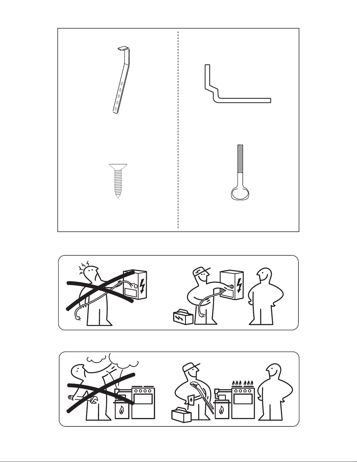
The electrical power to the cooktop must
be shut off while gas line connections are
being made. Failure to do so could result
in serious injury or death.
WARNING!

6 AA-2194924-3
Figure 2a – CABINET DESIGN
2x 2x
2x
2x
Installation Bracket Type 1 Installation Bracket Type 2

7
B
C
A
18” Min.
(45.7 cm)
24” Min.
(61 cm)
Figure 2a – CABINET DESIGN
2" (5.1 cm) Minimum Distance
Between Rear Edge of Cutout and
Nearest Combustible Surface Above
Countertop.
*See Figure 2c
Clearance
15" (38.1 cm)
Max. Depth
For Cabinet
Installed Above
Cooktop.
MODEL A B. Minimum
Clearance from
Left Side
C. Minimum
Clearance from
Right Side
30" Cooktop 30" (76.2 cm) 12" (30.5 cm) 12" (30.5 cm)
36" Cooktop 36" (91.4 cm) 12" (30.5 cm) 12" (30.5 cm)
To eliminate the risk of burns or re from reaching over heated surfaces, cabinet storage space
located above the cooktop should be avoided. If cabinet storage is provided, risk can be reduced
by installing a range hood that projects horizontally a minimum of 5" (12.7 cm) beyond the
bottom of the cabinets. Never store ammable products in the drawer.
CAUTION!
Figure 2b– Minimum
Recommended Distance From
Behind the Cabinet Front
1⅛"
(2.9 cm)
34" (86.4 cm) Min.
Clearance Between
the Top of the Cooking
Platform and Unprotected
Wood or Metal Cabinet
If a drawer is present underneath, allow
at least 6½" (16.5 cm) of clearance below
the counter top. Make sure there will be no
interference with gas or electrical connection.
Island Installation
Typical Installation
2"
(5 cm)
Wall
backsplash
Figure 2c– Minimum Recommended
Distance Between Rear Edge of
Cutout and Nearest Combustible
Surface Behind Countertop

8 AA-2194924-3
TYPICAL UNDER COUNTER INSTALLATION OF
AN ELECTRIC BUILT-IN OVEN WITH A COOKTOP
MOUNTED ABOVE
Figure 3
CUTOUT DIMENSIONS (INCHES (CM))
OVEN SIZE F. WIDTH G.
DEPTH H. HEIGHT
Min. Max. Min. Min. Max.
30" (76.2) 28½"
(72.4) 29"
(73.7) 23½"
(59.7) 27¼"
(69.2) 28½"
(72.4)
Only certain cooktop models may be
installed over certain built-in electric
oven models. Approved cooktops and
built-in ovens are listed by the MFG
ID number and product code (see the
insert sheet included in the literature
package and cooktop installation
instructions for the dimensions).
G
F
H
35¾” Min.
(90.8 cm) Min.
Use 3/4” (1.9 cm) plywood, installed
on two runners, ush with toe plate.
Base must be capable of supporting
200 pounds (90 kg).
Cut an opening in wood base minimum
9” x 9” (23 X 23 cm), 2” (5 cm) from
left side ller panel, to route armoured
cable to junction box.
208/240 Volt junction box
for built-in oven.
Approx. 3”
(7.5 cm)
Cabinet side ller panels are
necessary to isolate the unit from
adjoining cabinets. Cabinet side ller
height should allow for installation
of approved cooktop models
5” (12.7 cm) Max.
To reduce the risk of
personal injury and
tipping of the wall oven,
the wall oven must be
secured to the cabinet (s)
by mounting brackets.
WARNING

9
Wall Oven Cabinet
TYPICAL GAS COOKTOP INSTALLATION OVER
AN ELECTRIC BUILT-IN OVEN INSTALLED
UNDER THE COUNTER
GAS COOKTOP
18” (45.7 cm)
Max.
5”
(12.7 cm)
Flare
Union
4” (10.2 cm)
120V/60Hz
Grounded
Outlet Right Side
of Cabinet
Pressure
Regulator
Flare
Union
Flexible Connector
Cabinet sides
or ller panel
6½”
(16.5 cm)
Min.
Manifold Pipe
Manual Shutoff Valve
(To be accessible
for shut-off valve
operation)
Figure 4

10 AA-2194924-3
4. Once the cooktop is installed, insert the angle
bracket into the slot on each side of the unit as
shown (Fig. 6a) run wood screw to clamp the
unit down.
5. If you are using Installation Bracket type 2,
insert the thumb screw supplied (2) in the angle
bracket as shown below (Fig. 6b):
1. Wall Outlet Location
Figure 5
2. Cooktop Installation
Figure 6c
Countertop
Cooktop (Glass
or Porcelain)
Angle Bracket
Seal (Porcelain Cooktop
Only)
Wood Screw
Figure 6a
Angle
Bracket
Thumb
Screw
¾" to 1"
(1.9 to 2.5 cm)
Figure 6b
NOTE: Your gas cooktop includes 2 different bracket
and screw options. Select the bracket and screw
that works best with your installation.
1. Visually inspect the cooktop for damage.
2. Set the cooktop into the countertop cutout.
After inserting the cooktop into the countertop
opening, make sure the unit is sitting on the
metal ange around the top of the burner
box. Cooktop must not sit on the glass or the
porcelain top. Avoid cutting an oversized hole in
the countertop.
3. If you are using Installation Bracket type 1,
insert the Angle Bracket as shown below
(Fig. 6a):
Countertop
Thumb Screw
Angle Bracket
Cooktop (Glass
or Porcelain)
6. Once the cooktop is installed, clamp the unit
down, insert the angle bracket into the slot on
each side of the unit as shown (Fig. 6c). Run
the thumb screw up through the bracket, up
against the bottom of the counter. Tighten until
the unit draws down and is secure.

11
3. Provide an Adequate Gas
Supply
This cooktop is designed to operate on natural gas
at 5" of manifold pressure only.
A pressure regulator is connected in series with
the manifold on the cooktop and must remain in
series with the supply line.
For proper operation, the maximum inlet pressure
to the regulator must be no more than 14" of
water column (W.C.) pressure.
For checking the regulator, the inlet pressure
must be at least 1" (or 2.5 kPa) greater than the
regulator manifold pressure setting. The regulator
is set for 5" of manifold pressure, the inlet
pressure must be at least 6".
The gas supply line to the range should be 1/2" or
3/4" pipe.
4. LP/Propane Gas Conversion
This appliance can be used with Natural gas or LP/
Propane gas. It is shipped from the factory for use
with natural gas.
5. Install Pressure Regulator
Install the pressure regulator with the arrow on
the regulator pointing up toward the unit in a
position where you can reach the access cap.
A kit for converting to LP gas is supplied with your
cooktop. The kit is marked "FOR LP/PROPANE GAS
CONVERSION".
The conversion must be performed by a qualied
service technician in accordance with the kit
instructions and all local codes and requirements.
Failure to follow instructions could result in serious
injury or property damage. The qualied agency
performing this work assumes responsibility for
the conversion.
Important: Remove all packing material and
literature from cooktop before connecting gas and
electrical supply to cooktop.
Assemble the exible connector from the gas
supply pipe to the pressure regulator in the
following order:
All connections must be wrench-tightened
Figure 7
Failure to make the appropriate conversion can
result in serious personal injury and property
damage.
WARNING
Do not make the connection too tight. The
regulator is die cast. Overtightening may
crack the regulator resulting in a gas leak and
possible re or explosion.
WARNING
1. manual shutoff valve
2. 1/2" (1.3 cm) nipple
3. 1/2" (1.3 cm) are union adapter
4. exible connector
5. 1/2" (1.3 cm) are union adapter
6. 1/2" (1.3 cm) nipple
7. pressure regulator
Use pipe-joint compound made for use with
Natural and LP/Propane gas to seal all gas
connections. If exible connectors are used, be
certain connectors are not kinked.
The supply line must be equipped with an
approved manual shutoff valve. This valve should
be located in the same room as the cooktop and
should be in a location that allows ease of opening
and closing. Do not block access to the shutoff
valve. The valve is for turning on or shutting off
gas to the appliance.

12 AA-2194924-3
6. Electrical Requirements
120 volt, 60 Hertz, properly grounded branch
circuit protected by a 15 amp circuit breaker or
time delay fuse. Do not use an extension cord with
this cooktop.
Grounding Instructions
IMPORTANT: Please read carefully.
For personal safety, this appliance must be
properly grounded.
The power cord of this appliance is equipped with
a 3-prong (grounding) plug which mates with a
standard 3-prong grounding wall receptacle (see
Figure 9) to minimize the possibility of electric
shock hazard from the appliance.
The wall receptacle and circuit should be checked
by a qualied electrician to make sure the
receptacle is properly grounded.
Preferred Method
Grounding type
wall receptacle
Do not, under any
circumstances,
cut, remove,
or bypass the
grounding prong.
Power supply cord with
3-prong grounding plug.
Where a standard 2-prong wall receptacle is
installed, it is the personal responsibility and
obligation of the consumer to have it replaced by
a properly grounded 3-prong wall receptacle.
Do not, under any circumstances, cut or remove
the third (ground) prong from the power cord.
Figure 9
Disconnect electrical supply cord from wall
receptacle before servicing cooktop.
WARNING
Tighten all connections if necessary to prevent gas
leakage in the cooktop or supply line.
Check alignment of control knob valves after
connecting the cooktop to the gas supply to be
sure the cooktop manifold pipe has not moved. A
misalignment could cause the valve stems to rub
on the control panel, resulting in a gas leak at the
valve.
Disconnect this cooktop and its individual manual
shutoff valve from the gas supply piping system
during any pressure testing of that system at test
pressures greater than 1/2 psig (3.5 kPa or 14"
water column).
Isolate the cooktop from the gas supply piping
system by closing its individual manual shutoff
valve during any pressure testing of the gas
supply piping system at test pressures equal to or
less than 1/2 psig (3.5 kPa or 14" water column).
Once regulator is in place, open the shutoff valve
in the gas supply line. Wait a few minutes for gas
to move through the gas line.
Check for leaks. After connecting the cooktop to
the gas supply, check the system for leaks with a
manometer. If a manometer is not available, turn
on the gas supply and use a liquid leak detector
(or soap and water) at all joints and connections
to check for leaks.
Do not use a ame to check for leaks from gas
connections. Checking for leaks with a ame
may result in a re or explosion.
WARNING
Figure 8
Shutoff Valve -
Open position
to appliance to gas supply line

13
7. Check Operation
Refer to the User manual packaged with the
cooktop for operating instructions and for care and
cleaning of your cooktop.
Do not touch the burners. They may be hot
enough to cause burns.
1. Remove foam caps.
2. Turn on Electrical Power and Open Main Shutoff
Gas Valve
3. Check the Igniters
Operation of electric igniters should be checked
after cooktop and supply line connectors
have been carefully checked for leaks and the
cooktop has been connected to electric power.
To operate the surface burner:
A. Push in and turn a surface burner knob
to the LITE position. You will hear a small
ticking noise; this is the sound of the
electric ignitor which lights the burner.
B. After the burner lights, turn to the desired
ame size. The controls do not have to be
set at a particular mark. Use the marks as
a guide and adjust the ame as needed.
4. Adjust the "LOW" Setting of Surface Burner
Valves
When All Hookups are Complete
Make sure all controls are left in the OFF position.
Make sure the ow of combustion and ventilation air
to the cooktop is unobstructed.
Burner Flame Size
Main
Top
A. Push in and turn each control to LITE until burner
ignites.
B. Push in and quickly turn knob to LOWEST
POSITION.
C. If burner goes out, Reset control to OFF.
D. Remove the surface burner control knob.
E. Insert a thin-bladed screwdriver into the hollow
valve stem and engage the slotted screw inside.
Flame size can be increased or decreased with the
turn of the screw.
Do not remove center screw.
WARNING
NOTE: On models with twin burners (two rings of
ame), only the outer burner is adjustable.
Adjust ame until you can quickly turn knob from LITE
to LOWEST POSITION without extinguishing the ame.
Flame should be as small as possible without going
out.
Note: Air mixture adjustment is not required on
surface burners.
Figure 10
Figure 11
Model and Serial Number
Location
The rating plate is located on the underside of the
cooktop.
When ordering parts for or making inquires about
your range, always be sure to include the model
and serial numbers and a lot number or letter
from the rating plate of your cooktop.
Your rating plate also tells you the rating of the
burners, the type of fuel and the pressure the
cooktop was adjusted for when it left the factory.
Before You Call for Service
Read the Before You Call for Service Checklist
and operating instructions in your User manual. It
may save you time and expense. The list includes
common occurrences that are not the result
of defective workmanship or materials in this
appliance.
Refer to the warranty in your User manual for our
service phone number and address. Please call or
write if you have inquiries about your product and/
or need to order parts.

14 AA-2194924-3
PARA SU SEGURIDAD: No almacene o utilice gasolina u otros
vapores y liquidos inamables cerca de éste o cualquier otro
artefacto
LA INSTALACIÓN Y EL SERVICIO DEBEN SER REALIZADOS POR
UN INSTALADOR CALIFICADO. IMPORTANTE: GUARDE ESTAS
INSTRUCCIONES PARA USO DEL INSPECTOR ELÉCTRICO LOCAL.
LEA Y GUARDE ESTAS INSTRUCCIONES
PARA FUTURAS REFERENCIAS
Su seguridad y la seguridad de los demás son muy importantes.
Hemos proporcionado muchos mensajes de seguridad importantes en este manual y en su
electrodoméstico. Siempre lea y obedezca todos los mensajes de seguridad.
Éste es el símbolo de alerta de seguridad.
Este símbolo lo alerta sobre posibles peligros que pueden matarlo o lastimarlo a usted y
a otros. Todos los mensajes de seguridad seguirán el símbolo de alerta de seguridad y la
palabra "ADVERTENCIA" o "PRECAUCIÓN".
Indica una situación potencialmente peligrosa que, si no se
evita, puede provocar la muerte o lesiones graves.
Indica una situación potencialmente peligrosa que, si no se
evita, puede provocar lesiones leves o moderadas.
Todos los mensajes de seguridad le dirán cuál es el peligro potencial, cómo reducir la posibilidad de
lesiones y qué puede suceder si no se siguen las instrucciones.
¡PRECAUCIÓN!
¡ADVERTENCIA!
Peligro de descarga eléctrica
Desconecte la energía antes de dar servicio.
Use alambre de cobre sólido de calibre 12.
Horno electricamente molido.
El incumplimiento de estas instrucciones
puede provocar la muerte, incendio o
descarga eléctrica.
Si todas las instrucciones de éste manual no
son observadas a la letra, se puede ocurrir
incendios o explosiones que pueden causar
daños materiales, lesiones o la muerte.
PARA SU SEGURIDAD:
— No almacene o utilice gasolina u otros
vapores y liquidos inamables cerca
de éste o cualquier otro artefacto.
— QUE HACER SI HAY FUGAS DE GAS :
• No intente de encender ningún artefacto
• No toque ningún interruptor eléctrico; no
utilice ningún aparato telefónico en su
edicio.
• Llame inmediatamente el abastecedor de
gas desde el teléfono de un vecino. Siga las
instrucciones del abastecedor de gas.
• En caso que no puede contactar el
abastecedor de gas llame al departamento
de bomberos.
— La instalación y el servicio telefónico deben
ser realizados por un instalador calicado,
por un servicio técnico certicado o por el
abastecedor de gas.
Aparatos Instalados en el estado de
Massachusetts:
Este Aparato sólo puede ser instalado en el estado
de Massachusetts por un plomero o ajustador de
gas licenciado de Massachusett.
Este aparato se debe instalar con un largo conector
exible de gas de tres (3) pies/36 pulgadas.
Una válvula manual de gas de tipo manija de forma
de "T" se debe instalar en la línea del suministro de
gas de este aparato.
¡ADVERTENCIA!
¡ADVERTENCIA!

15

16 AA-2194924-3
Gas Cooktop
Cutout Dimensions
Gas Cooktop
Dimensions
3¼”
(8.3 cm)
G
34” Min. *
(86.4 cm)
H
AB
C
D
E
F
Todas las dimensiones se dan en pulgadas (cm).
La dimensión H incluye un espacio de 5" por debajo de la plancha de cocinar para la conexión de la línea de
suministro de gas.
Figura 1
Notas importantes para el instalador:
1. Lea todas las instrucciones de instalación antes
de realizar la instalación de la plancha de
cocinar.
2. Retire todos los artículos de embalaje antes de
realizar las conexiones eléctricas a la plancha de
cocinar.
3. Observe todos los códigos o reglamentos
estatales
4. Asegúrese que el consumidor tenga estas
instrucciones.
5. Nota: Para el correcto funcionamiento en
lugares superiores a los 2000 ft, el régimen del
mecanismo debe reducirse un 4% por cada 1000
ft sobre el nivel del mar.
6. Todos los materiales utilizados en la construcción
de gabinetes, gabinetes y soportes que rodean
el producto deben tener una temperatura
nominal superior a 194°F (90°C).
Notas importantes para el consumidor
Guarde todas las instrucciones con su manual del
usuario para futuras referencias.
Dimensiones
de la estufa de
gas
Dimensiones de corte
de la estufa de gas
DIMENSIONES DE LA PARRILLA DE COCINAR
MODELO A. ANCHURA B. PROFUNDI-
DAD C. ALTURA D. ANCHO DE LA
CAJA
E. PROFUNDIDAD DE LA CAJA
Modelo de 30" 30 (76.2) 21 ¾ (55.2) 4 ¼ (10.8) 28 (71.1) 19 3/8 (49.2)
Modelo de 36" 36 (91.4) 21 ¾ (55.2) 4 ¼ (10.8) 33 5/8 (85.4) 19 (48.3)
DIMENSIONES DEL HUECO DE LA PARRILLA DE COCINAR
F. ANCHURA G. PROFUNDIDAD H. ALTURA POR DEBAJO
DE LA ESTUFA
MODELO MÍNIMUM MÁXIMUM MÍNIMUM MÁXIMUM
Modelo de 30" 28 ¼ (71.8) 28 5/8 (72.7) 19 3/8 (49.2) 19 ¾ (50.2) 8 (20.3)
Modelo de 36" 33 7/8 (86) 34 ¼ (87) 19 3/8 (49.2) 19 ¾ (50.2) 8 (20.3)

17
INSTRUCCIONES
DE SEGURIDAD
IMPORTANTES
La instalación de esta plancha de cocinar debe
realizarse en conformidad con los códigos locales
o, si estos no existen, con el National Fuel Gas
Code ANSI Z223.1/NFPA 54 en los Estados Unidos,
o en Canada, con el Canadian Fuel Gas Code,
CAN/CGA B149 y CAN/CGA B149.2.
• La instalación de aparatos diseñados para
instalación en casas prefabricadas (móviles)
debe conformar con el Maufactured Home
Consturction and Safety Standard, título 24CFR,
parte 3280 [Anteriormente el Federal Standard
for Mobil Home Construction and Safety, título
24, HUD (parte 280)] o cuando tal estándar no
se aplica, el Standard fo Manufactured Home
Installation, ANSI/NCSBCS 225.1, o con los
códigos locales.
El diseño de esta plancha de cocinar cuenta con
la aprobación de la CSA internacional. Al igual
que todos los artefactos a gas que generan
calor, deben seguirse ciertas medidas de
seguridad. Vienen con el Manual del Usuario. Lea
atentamente el manual.
•Asegúrese que la plancha de cocinar sea
instalada y puesta a tierra correctamente
por un instalador o técnico calicado.
• La plancha de cocinar debe conectarse
eléctricamente a tierra de acuerdo con
los códigos locales o, de no existir, con el
código eléctrico ANSI/NFPA No. 70 - última
edición en los Estados Unidos, or in Canada,
con el Canadian Electrical Code, CSA C22.1
Parte 1.
• Los quemadores pueden encenderse
manualmente durante una interrupción
del suministro eléctrico. Para encender
un quemador, mantenga un fósforo
encendido en el extremo del quemador,
luego gire suavemente la perilla hasta LITE
(encendido). Tenga cuidado al encender los
quemadores en forma manual.
• No deje artículos que interesan los niños en
los armarios que están sobre la plancha de
cocinar. Les podría causar quemaduras graves
si intentan subirse para alcanzarlos.
• Para eliminar el riesgo de extender
por encima de los quemadores
superiores, debería evitar el espacio de
almacenamiento del armario, localizado por
encima de estos quemadores
• Gradúe el tamaño de la llama de modo
que no sobrepase el borde del utensilio de
cocina. Demasiada llama es peligrosa.
• No utilice jamás la cocina como calefactor.
El uso prolongado de la cocina sin la ventilación
adecuada puede ser peligroso.
• Mantenga el área cerca de este artefacto
o de cualquier otro artefacto despejada
de sustancias combustibles, gasolina y
otros líquidos inamables. Se puede ocurrir
incendios o explosiones.
El suministro eléctrico a la plancha de
cocinar debe de ser cerrado durante las
conexiones a la línea. De lo contrario se
puede resultar lesiones graves o la muerte.
¡ADVERTENCIA!

18 AA-2194924-3
2x 2x
2x
2x
Soporte de instalación tipo 1 Soporte de instalación tipo 2
Figure 2a – DESEÑO DEL ARMARIO

19
MODELO DE
PLANCHA DE
COCINAR
A B. Espacio
mínimo desde el
lado izquierdo
C. Espacio mínimo
desde el lado derecho
Modelo 30" 30" (76.2 cm) 12" (30.5 cm) 12" (30.5 cm)
Modelo 36" 36" (91.4 cm) 12" (30.5 cm) 12" (30.5 cm)
B
C
A
18” Min.
(45.7 cm)
24” Min.
(61 cm)
Figure 2a – DESEÑO DEL ARMARIO
2" (5.1 cm) Mínimo Distancia entre
el borde posterior del hueco y la
más cerca supercie combustible por
encima del mostrador..
*See Figure 2c
Espacio
Máx. profundidad de
gabinetes instalados
por encima de la
plancha de empotar
es 15" (38.1 cm).
Para eliminar el riesgo de alargar sobre los unidades en calentamiento de la supercie, debería
evitarse el espacio de almacenamiento del armario, ubicado sobre las unidades de la supercie.
Si se cuenta con este espacio, se puede disminuir el peligro instalando una cubierta de cocina que
se extienda horizontalmente en 5" (12.7 cm) mínimo por sobre la parte inferior delantera en los
armarios. Nunca almacene productos inamables en el cajón.
Figura 2b– Distancia mínima
recomendada desde detrás del
frente del gabinete
1⅛"
(2.9 cm)
34" (86.4 cm) Mínimo
de espacio entre la parte
superior de la plataforma
de la plancha de cocinar
y el fondo de una madera
non protegida o armario
metálico.
Si hay un cajón debajo, dejar al menos 6½"
(16.5cm) de espacio libre con respecto a la
supercie del mueble. Asegurarse de que no habrá
interferencia con alguna conexión de gas o eléctrica.
¡PRECAUCIÓN!
Instalación de isla
Installation typique
2"
(5 cm)
Pared
protector contra salpicaduras
Figura 2c– Distancia mínima
recomendada entre el borde
posterior del corte y la supercie
combustible más cercana detrás
de la encimera

20 AA-2194924-3
TÍPICA INSTALACIÓN DE UN HORNO ELÉCTRICO
EMPOTRADO CON UNA PLANCHA
DE COCINAR POR ENCIMA
Figura 3
Sólo ciertos modelos de tapas de cocina se pueden
instalar sobre ciertos modelos de hornos eléctricos
empotrados. Las tapas de cocina y los hornos
empotrados se mencionan por su número de
identicación MFG ID y código de producto (ver la
planilla que se incluye en el paquete de literatura y
las instrucciones de instalación de la cocina donde
están detalladas las dimensiones).
G
F
H
35¾” Min.
(90.8 cm) Min.
Instale contrachapado de 3/4" (1.9 cm)
sobre dos correderas, nivelado con la
parrilla inferior. La base debe poder
sostener 200 libras (90 kg).
Corte una abertura de 9" X 9"(23 cm X 23 cm)
(mínimo) en el fondo del contrachapado, a 2"
(5 cm) del lado izquierdo del panel llenador,
para poder encaminar el cable a la caja de
empalme.
208/240 caja de empalme
para hornos de pared
Approx. 3”
(7.5 cm)
Los paneles de relleno laterales
del gabinete son necesarios
para aislar la unidad de los
gabinetes adyacentes. La altura
de llenado lateral del gabinete
debe permitir la instalación de
modelos de estufa aprobados
5” (12.7 cm) Max.
Para reducir el riesgo
de lesiones personales
y inclinación del horno
de pared, éste debe
asegurarse a los gabinetes
mediante soportes de
montaje.
¡ADVERTENCIA!
DIMENSIONES DE ABERTURA (PULGADAS (CM))
HORNO
DE
PARED
F. ANCHURA G. PROFUNDIDAD H. ALTURA
Min. Máx. Min. Min. Máx.
30" (76.2) 28½"
(72.4) 29"
(73.7) 23½" (59.7) 27¼"
(69.2) 28½"
(72.4)
This manual suits for next models
1
Table of contents
Languages:
Other IKEA Cooktop manuals

IKEA
IKEA ICS300RQ04 User manual

IKEA
IKEA SAMFALLD User manual

IKEA
IKEA w10297312b User manual

IKEA
IKEA GAS SEALED BURNER COOKTOP User manual

IKEA
IKEA ICR500XB00 User manual

IKEA
IKEA ICR500XB00 User manual

IKEA
IKEA TYDLIG User manual

IKEA
IKEA Nutid HGA3K User manual

IKEA
IKEA GRUNDAD User manual

IKEA
IKEA Lagan HGA4K User manual