ii
_____________________________________________________________________________________________
______________________________________________________________________________________________
WARNING
This product is designed to conform to IEC 61010 Safety Standards, and
has been thoroughly tested for safety prior to shipment. However,
mishandling during use could result in injury or death, as well as
damage to the product. Be certain that you understand the instructions
and precautions in the manual before use. We disclaim any
responsibility for accidents or injuries not resulting directly from
product defects.
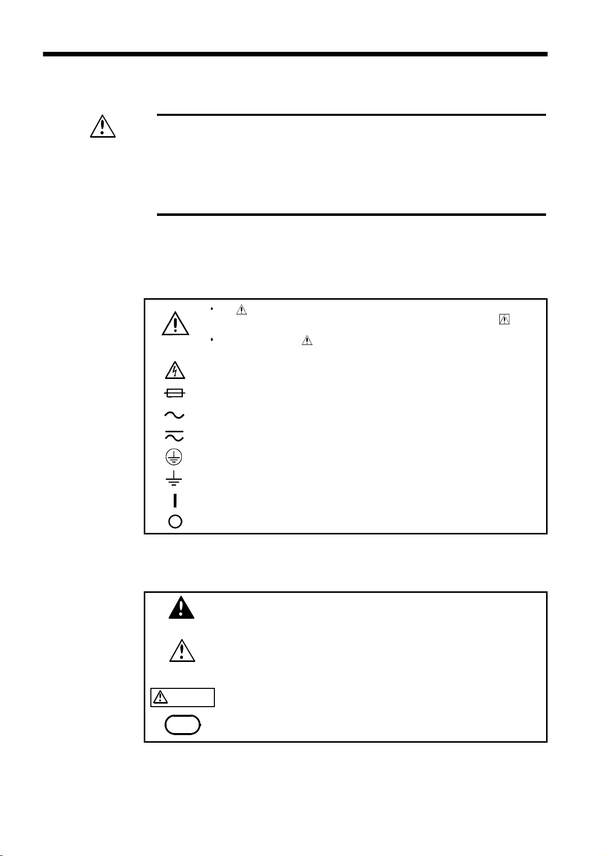
Safety Symbols
The symbol printed on the product indicates that the user should
refer to a corresponding topic in the manual (marked with the
symbol) before using the relevant function.
In the manual, the symbol indicates particularly important
information that the user should read before using the product.
Indicates that dangerous voltage may be present at this terminal.
Indicates a fuse.
Indicates AC (Alternating Current).
Indicates both DC (Direct Current) and AC (Alternating Current).
Indicates a protective conductor terminal.
Indicates a grounding terminal.
Indicates the ON side of the power switch.
Indicates the OFF side of the power switch.
DANGER
Indicates that incorrect operation presents an extreme hazard that
could result in serious injury or death to the user.
WARNING
Indicates that incorrect operation presents a significant hazard that
could result in serious injury or death to the user.
CAUTION Indicates that incorrect operation presents a possibility of injury to
the user or damage to the product.
NOTE Advisory items related to performance or correct operation of the
product.
Safety Notes
This manual contains information and warnings essential for safe operation
of the product and for maintaining it in safe operating condition. Before
using the product, be sure to carefully read the following safety notes.
The following symbols in this manual indicate the relative importance of
cautions and warnings.