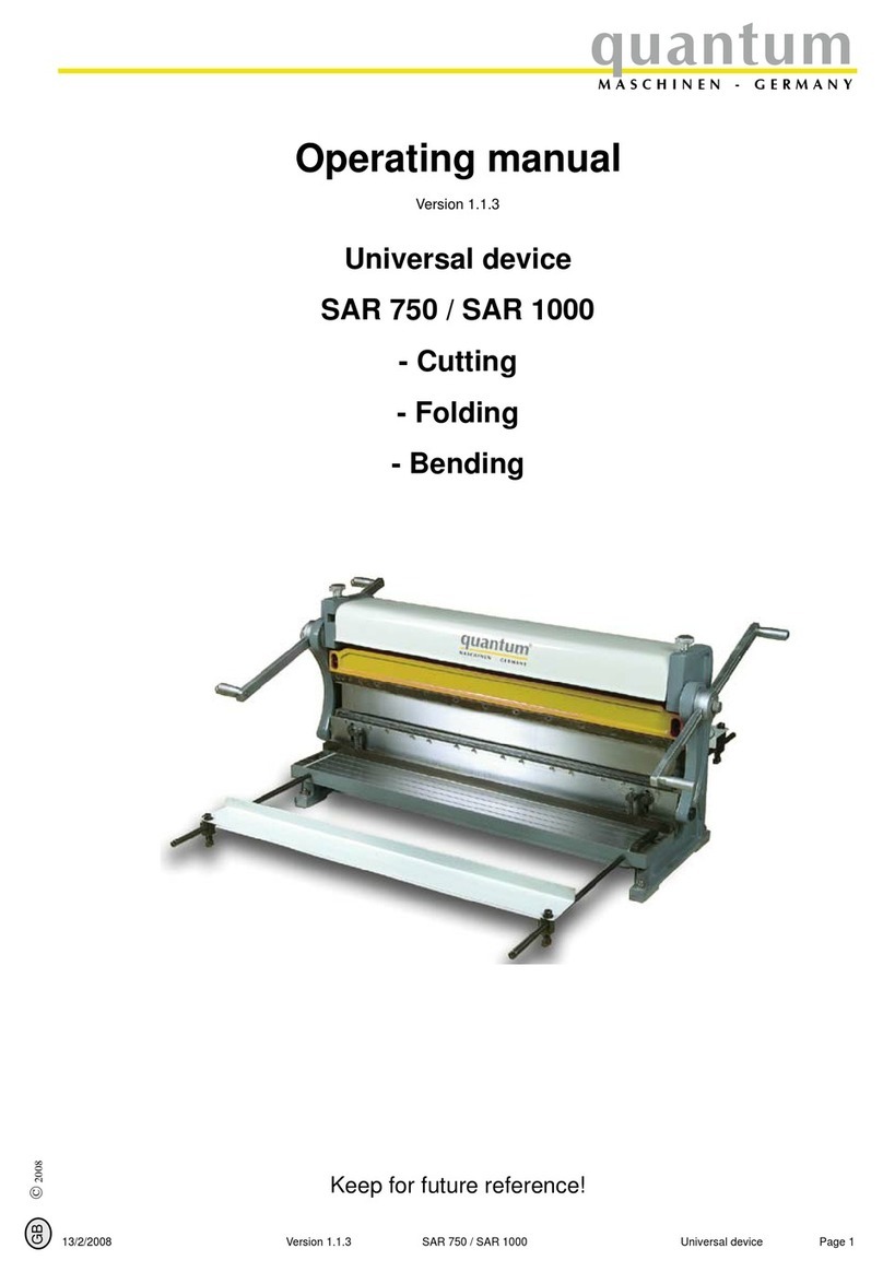
Tin Knocker TK 816 Parts list manual

1
TIN KNOCKER
TK 816 LEAF BRAKE
INSTRUCTIONS & PARTS DIAGRAM
TAAG MACHINERY CO.
(Master Distributor)
1257-B Activity Dr.
Vista, CA 92081
Tel: (800) 640-0746 Fax: (760) 727-9948
Website: www.tinknocker.com * Email: taag@sbcglobal.net
01082007 mod 1

2
TIN KNOCKER
SAFETY RULES
TK 816 LEAF BRAKE
1. Never use a machine or tool for anything other than its intended purpose. Use the proper tool and
equipment for the task.
2. Do not operate the machine in excess of its rated capacity.
WARRANTY
All new machines are sold with a one-year limited warranty, on factory defective parts. The warranty is
limited to the original user. TAAG Machinery Co. at its option, will repair, replace or refund the purchase
price of any part, tool or machine that fails during the warranty period. TAAG Machinery Co. will pay
normal shipping charges for replacement parts. After 90 days from date of purchase, all express or
overnight delivery charges are the responsibility of the customer. Purchaser must deliver to TAAG
Machinery Co., at the address below, any written claim, with proof of original purchase. Replacement parts
will be invoiced to purchaser and credit issued when the failed part is delivered to TAAG Machinery Co.
Removal, reinstallation or replacement parts shall be at purchasers’ / user’s expense. Failure due to
improper use of the machine voids the warranty.
NOTE: 1. This machine has been tested and adjusted prior to shipment, but can and often does require
readjustment due to vibration and bouncing during transport. Following the procedures described within
can easily do readjustment. These are procedures with which you, as a user, should be familiar, as you will
use them repeatedly over the life use of the machine. If you have difficulty in performing these procedures,
we are here to support you. Call us at: (800) 640-0746.
2. Opening rolls (for Philipsburg Lock) are consumable items and not subject to warranty.
TAAG MACHINERY CO.
(Master Distributor)
1257-B Activity Dr.
Vista, CA 92081
Tel: (800) 640-0746 Fax: (760) 727-9948
Website: www.tinknocker.com * Email: taag@sbcglobal.net

3
TK 816 Leaf Brake
RECEIVING THE MACHINE
Inspect before signing Bill of Lading.
Upon receipt closely examine the Leaf Brake for damage during shipment. Any loss or damage should
be noted in detail on the delivery receipt and reported to your distributor immediately. Free replacement
from TK International is dependant upon the notation and the Bill of Lading on delivery slip.
INSTALLING THE MACHINE
Locate the Leaf Brake in a well-lighted area on a solid, level floor. The Leaf Brake must be securely
bolted to the floor. Be sure you have adequate room to swing both handles and Bending Leaf.
PRECAUTIONS
DO NOT use the Leaf Brake to bend rods, nails or wires. This will cause damage to the edge of the top
blade. DO NOT exceed the capacity of the Leaf Brake.
OPERATING & ADJUSTMENT OF THE TK 816
Adjusting for Metal Thickness
Clearance for bends is obtained by moving Top Leaf back at bending edge. If material is to be bent is
within four gauges of capacity, move the Top Leaf back twice the thickness of the material. With lighter
material, move Top Leaf proportionately forward if sharper bends are desired.
1. Unclamp Handles (H) slightly.
3. Loosen Top Adjustment Plate Bolt (N). Adjust Top Leaf with Top Adjustment Bolts (L). Tighten
Locking Nuts and Top Adjustment Plate Bolt (N). Clamping pressure of the Links (K) is changed
by adjusting the Nuts. (M)
Duplicate Bends
Adjustable Stop Gauge (O) may be positioned at any point on Rod (P) by means of Lock Bolt (Q) to
limit the degree of bend.
Counterbalance
Counterweight (J) can be raised or lowered on Rod to properly counterbalance the Bending Leaf.
Overbending Adjustment
If sheet bends over further on one side than the other/ set the Top Leaf back on the end where sheet is
overbending.
1. Unclamp Handles (H) slightly on side that is over bending.
2. Adjust Top Leaf with Top Adjustment Bolts (L).
3. Reclamp Handle (H).

4
Creeping Top Leaf Adjustments
Should Top Leaf creep forward when clamping material:
1. Check that brake sets level on floor.
2. Check Top Adjustment Plate (M) and Top Adjustment Bolts and Lock Nuts (L) to eliminate any
movement of step bracket (15).
3. If still creeping, wedge under rear of Leg (A) at end that creeps until stopped. Replace wedge
with permanent block of correct height.
Capacity:
The bending capacity of the brake is determined by the bending edge thickness provided by the Bending
Leaf Bars (U/V) when mounted on Leaf.
1. Insert Bar (U) with Angle Bar (V) allow the full rated 1" minimum flange on capacity material.
2. Insert Bar alone without Angle Bar reduces capacity of brake four gauges.
3. Removing both Insert Bar and Angle Bar reduces capacity of brake seven gauges. These Bars are
removed only to make narrow offset bends.
Narrow Offset Bends
Remove Angle Bar (V) and Insert Bar (U) - use Bending Leaf only.
Cautions
Bend short pieces of material in center of brake to equalize the strain. Never bend against seams unless
Links (K) are adjusted to clamp the full multiple thickness of seam; and Top Leaf is set back for clearance
of the same full multiple thickness. Always have both Angle Bar (V) and Insert Bar (U) mounted to Lead
when making capacity bends. When forming sections of wide girth such as cornices, to equalize the
buckles in the sheet:
1. Start bend near the center of sheet, or,
2. Make a kink in the opposite end of sheet from the bend first made.
Sheets are not always perfectly flat and a buckle left in one end while the other is straightened by clamping
in the brake will throw the first bend out of line when it, in turn, is straightened.
Always use material with square-sheared edges - rolled-edges will cause material to bow.
Never use brake to bend rods - these will nick Nose Bar. Always adjust for differences in the metal
gauges. N
ever
force-clamp the material.
Lubrication
Lubricate occasionally with SAE-30 oil.

5

6
Parts For 816 Leaf Brakes
Fine
No.
Part
No.
Description
No.
REQ"D.
801 816101
801 Holddown Assy. 1
1 816102
Top Blade 1
2 816103
Screw 17
3 816134
Toggle Assy. Nut 4
4 816104
Spring Cover Assy. Bolt 2
5 816105
Spring Cover Assy. 2
6 816106
Clamp Handle R.H. 1
7 816107
Clamp Handle L.H. 1
8 816108
Toggle Assy. R&L 1
9 816109
Toggle Assy. R&L 1
10 816110
C-Clip 2
11 816111
Bushing 2
802 816112
802 Base Assy. 1
13 816113
Screw 4
14 816114
Locknut & Washer 2
15 816115
Step Bracket Comp. R.H. 1
16 816116
Step Bracket Comp. L.H. 1
17 816117
Pin 2
18 816118
Swivel Pin Assy. 2
19 816119
Rod 2
20 816120
Counterweight 2
21 816121
Support, Apron Assy. R.H. 1
22 816122
Support, Apron Assy. L.H. 1
23 816123
Gauge Stop 1
24 816124
Gauge Rod 1
803 816125
803 Apron Assy. 1
25 816126
Plate, Fixing 2
26 816127
Screw, Fixing 8
27 816128
Insert Bar 1
28 816129
Angle Bar 1
29 816130
Flat Head Screw 12
30 816131
Screw 7
31 816132
Stand 2
32 816133
Screw Assy. 6
33 816135
Snap Ring 2
34 816136
Lifting Handle 2
Table of contents
Popular Cutter manuals by other brands

Makita
Makita 3706 instruction manual

Universal Laser Systems
Universal Laser Systems X-600 Safety, installation, operation, and basic maintenance manual
JRC
JRC DCST manual
Graco
Graco GrindLazer Pro RC813 G Operation, repair, and parts

HOLZMANN MASCHINEN
HOLZMANN MASCHINEN UBM305 user manual
SPEWE
SPEWE ES-5300 manual
