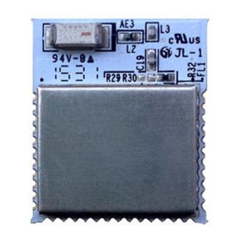
iLumi MESHTEK-H52E User manual

……………..
© ilumi Solutions Inc www.ilumisolutions.com P a g e 1 | 13
MESHTEK-H52E
FEATURES
Simple & fast integration with development
kits and sample iOS & Android API
Built-in reliable Connection based mesh to
support large data packets, Mesh Network
(Node and Bridge) for Android
Long-range, module connectivity up to 100
meters
Compact form factor 15.24mm X 17.60mm X
3mm
Castellated SMT pads for easy and reliable
PCB mounting
Over the Air firmware update from one
device to an entire network
32-bit ARM® Cortex™ M4F nRF52832 CPU
Proximity support for beacon and location
based services
No. of GPIOs available for user - 11
Configurable I/O mapping for analog and
digital
Simultaneous master and slave operation
*Certifications: FCC, IC (In progress)
RoHS compliant
OPERATIONAL
•Operating voltage range: 1.7V to 3.6VDC
•Temperature range: -40°C to 85°C
•Low-power consumption
•Interface: SPI, UART, I2C
•512KB flash and 64KB RAM
APPLICATIONS
Lighting fixtures
Automotive
Home Automation
Power plugs, routers
Internet of Things (IoT)
Industrial Control
DESCRIPTION
With the smartest and most robust Bluetooth
Mesh Network technology on the market, ilumi’s
MeshTek provides an elegant and affordable
solution for manufacturers looking to quickly and
reliably bring BLE enabled IoT products to market.
The MESHTEK-H52E Smart Mesh Module with IPX
antenna allows users to connect External Antenna
which is required for various applications. This
complete platform solution includes software
drivers, sample applications, API guide, user
documentation and a world-class support.
The MESHTEK-H52E internal controller can be used
for applications up to 64KB flash; without the need
for external host MCU or software development
tools.
MESHTEK-H52E Bluetooth Module
with External Antenna

MESHTEK-H52E
ilumi solutions, inc. www.ilumisolutions.com http://www.ilumi.co/ P a g e 2 | 13
TABLE OF CONTENTS
1. DEVICE OVERVIEW ........................................................................................................................ 4
2. GENERAL SPECIFICATIONS ............................................................................................................ 6
3. PHYSICAL DIMENSIONS................................................................................................................. 7
4. LAYOUT AND MOUTING GUIDELINES ........................................................................................... 7
5. REGULATORY APPROVAL .............................................................................................................. 9
5.1. FCC AND IC COMPLIANCE ............................................................................................................. 9
5.1.1. FCC STATEMENT............................................................................................................................ 9
5.1.2. IC COMPLIANCE............................................................................................................................. 9
5.1.3. CONFORMITÉ AUX NORMS D´IC ................................................................................................. 10
5.1.4. OEM RESPONSIBILITIES TO COMPLY WITH FCC AND INDUSTRY CANADA REGULATIONS ......... 10
5.1.5. OEM LABELING REQUIREMENTS FOR END PRODUCT ................................................................ 10
6. PRODUCT HANDLING.................................................................................................................. 12
6.1. SOLDER REFLOW PROFILE........................................................................................................... 12
7. PACKAGING AND LABELLING ...................................................................................................... 13
7.1. PACKAGING................................................................................................................................. 13
7.2. PACKAGING LABEL ...................................................................................................................... 13
8. ORDERING INFORMATION.......................................................................................................... 13
9. REVISION HISTORY ...................................................................................................................... 13
Table 1: PINOUT DRESCPTION ......................................................................................................................5
Table 2: ELECTRICAL SPECIFICATIONS........................................................................................................... 6
Table 3: MESHTEK-H52E FCC and IC Conformity .......................................................................................... 8
Table 4: ORDERING INFORMATION ............................................................................................................12
Figure 1: MESHTEK-H52E BLOCK DIAGRAM..................................................................................................4
Figure 2: MESHTEK-H52E PINOUT ................................................................................................................ 4
Figure 4: MESHTEK-H52E FOOTPRINT ..........................................................................................................7
Figure 5: REFLOW PROFILE ...........................................................................................................................7

MESHTEK-H52E
ilumi solutions, inc. www.ilumisolutions.com http://www.ilumi.co/ P a g e 3 | 13
TO OUR VALUED CUSTOMERS
It is our intention to provide you, our valued customer, with the best possible documentation to ensure
successful use of your MeshTek products. To this end, we will continue to update our publications to better
suit your needs. Our publications will be refined and enhanced as new volumes and updates are introduced.
Please note: images used in the manual are for reference purposes and may be different than the actual
product.
If you have any questions or comments regarding this publication, please contact the Marketing
Communications Department via Email at sales@ilumisolutions.com. We welcome your feedback.
Errata
An errata sheet, describing minor operational differences from the data sheet and recommended
workarounds, may exist for current devices. As device/documentation issues become known to us, we will
publish an errata sheet. The errata will specify the revision of silicon and revision of the document to which it
applies.
To determine if an errata sheet exists for a particular device, please check with one of the following:
Contact the MeshTek team
Contact your local MeshTek sales representative
When contacting a sales office, please specify which device, revision of MeshTek-H52E data sheet (include
literature number) you are using.

MESHTEK-H52E
ilumi solutions, inc. www.ilumisolutions.com http://www.ilumi.co/ P a g e 4 | 13
1. DEVICE OVERVIEW
The MESHTEK-H52E Bluetooth Low Energy RF module integrates Bluetooth radio baseband, 32-bit MCU, digital
analog I/O, onboard MeshTek stack. Figure 1 shows the module’s Block diagram. Figure 2 shows the module’s
pinout and the description is shown in Table 1.
Figure 2: MESHTEK-H52E PINOUT
Figure 1: MESHTEK-H52E BLOCK DIAGRAM
Figure 1: MESHTEK-H52 PINOUTFigure 2:MESHTEK-H52 BLOCK
DIAGRAM
BLE
ARM Cortex M4F
CPU I/O
32MHz
Xtal
VDD (DC 1.7V to 3.6V)
SWD (2)
Programming Pins
I/O (11)
GND
Power
Amplifier
Band Pass
Filter
u.FL Connector

MESHTEK-H52E
ilumi solutions, inc. www.ilumisolutions.com http://www.ilumi.co/ P a g e 5 | 13
MESHTEK-H52E has u.FL connector present on the module, an external antenna with mating part needs to be
connected to the module.
Table 1: PINOUT DESCRIPTION
Sr. No.
Pin out
Pin Function
Description
1
GND
Power
Ground (0 V)
2
VDD
Power
Power Supply
3
P0.26
Digital I/O
General purpose I/O pin.
4
P0.27
Digital I/O
General purpose I/O pin.
5
P0.28
(AIN4)
Digital I/O
Analog input
General purpose I/O pin
SAADC/COMP/LPCOMP input
6
P0.29
(AIN5)
Digital I/O
Analog input
General purpose I/O pin
SAADC/COMP/LPCOMP input
7
P0.30
(AIN6)
Digital I/O
Analog input
General purpose I/O pin
SAADC/COMP/LPCOMP input.
8
P0.21
(RESET)
Digital I/O
General purpose I/O pin
Configurable as pin reset
9
P0.18
(TRACEDATA[0] /
SWO)
Digital I/O
General purpose I/O pin
10
P0.17
(MI2C_DATA)
Digital I/O
Digital output
General purpose I/O pin
I2C Data out
11
SWDCLK
Digital input
Serial Wire Debug clock input for debug and programming
12
SWDIO
Digital I/O
Serial Wire Debug I/O for debug and programming
13
P0.13
Digital I/O
General purpose I/O pin
14
P0.12
Digital I/O
General purpose I/O pin
15
P0.11
Digital I/O
General purpose I/O pin
Note: For more details, check out nRF52832 (QFN48) Cortex ARM M4F controller specifications

MESHTEK-H52E
ilumi solutions, inc. www.ilumisolutions.com http://www.ilumi.co/ P a g e 6 | 13
2. GENERAL SPECIFICATIONS
Table 2 provides the general specifications for the module and current consumption.
Table 2: ELECTRICAL SPECIFICATIONS
ELECTRICAL SPECIFICATIONS
Description
Min
Nom
Max
Notes
VDD - Supply Voltage
1.7V
3.0V
3.6V
Operating Temperature Range
-40 °C
85 °C
ESD - Human Body Model Class 2
4 kV
Built-in Crystal Frequency
32 MHz
Crystal Frequency Tolerance
+/- 10ppm
Reset pin time for successful reset
60 msec
Radio Operating Frequencies
2.402GHz 2.480 GHz
Radio On-Air Data Rate
1 Mbps
2 Mbps
Radio Output Power
+19dBm
RF output power
configured to +19dBm
using external PA in
continuous TX Mode
Receiver Sensitivity @ BLE Mode
-96 dBm
Ideal transmitter
Radio RSSI Accuracy
+/- 2 dB
UART Baud Rate
1000 kbps
SPI Bit Rate
0.125 Mbps
8 Mbps
TWI Bit Rate
100 kbps
400 kbps
Analog-to-Digital Converter (ADC)
Range
0
VDD
8/10/12-bit ADC
VIH –Input High Voltage
0.7 * VDD
VDD
VIL –Input Low Voltage
VSS
0.3 * VDD
VOH –Output High Voltage
VDD –0.4
VDD
VOL –Output Low Voltage
VSS
VSS + 0.4
Output standard drive current
20 mA
Pull-up resistance / Pull-down
resistance
11k
13k
16k
Transmit Current
90mA
+19dBm output Power
Receive Current
24.8mA
Radio RX Active
System ON, No RAM retention,
Wake on any event
1.2uA
System ON, Full RAM retention,
Wake on any event
1.5uA

MESHTEK-H52E
ilumi solutions, inc. www.ilumisolutions.com http://www.ilumi.co/ P a g e 7 | 13
3. PHYSICAL DIMENSIONS
Figure 4 shows the size and footprint for MeshTek-H52E module
Figure 4: MESHTEK-H52E FOOTPRINT
4. LAYOUT AND MOUTING GUIDELINES
We recommend 2 or more layers for the Carrier Board (Host PCB). The top side shall be mostly ground.
Signal routing shall be done in the bottom or middle layers.
When laying out the Carrier board for the MESHTEK-H52E module, the areas under the antenna and
shielding connections should not have signal traces, ground planes or exposed vias.
For the best Bluetooth range performance, the antenna area of module shall extend 6.3mm outside
the edge of Carrier Board or 6.3mm outside the edge of a ground plane.
For the best Bluetooth range performance, keep all external metal away from the antenna area.

MESHTEK-H52E
ilumi solutions, inc. www.ilumisolutions.com http://www.ilumi.co/ P a g e 9 | 13
5. REGULATORY APPROVAL
5.1. FCC and IC Compliance
The MESHTEK-H52E module conforms to the product specifications listed in below Table 4.
Table 3: MESHTEK-H52E FCC and IC Conformity
Standard
FCC
FCC part 15 Subpart C Section 15.249
MESHTEK-H52E FCC ID: 2AEHU-MESHTEK-H52E
IC
Industry Canada RSS-210
Industry Canada RSS-Gen
MESHTEK-H52E IC: 20059-MESHTEKH52E
5.1.1. FCC Statement
This device has been tested and found to comply with part 15 of the FCC rules. These limits are designed to
provide reasonable protection against harmful interference in a residential installation. This equipment
generates, uses and can radiate radio frequency energy and, if not installed and used in accordance with the
instructions, may cause harmful interference to radio communications. However, there is no guarantee that
interference will not occur in a particular installation. If this equipment does cause harmful interference to
radio or television reception, which can be determined by turning the equipment off and on, the user is
encouraged to try to correct the interference by one or more of the following measures:
Reorient or relocate the receiving antenna.
Increase the separation between the equipment and the receiver
Connect the equipment into an outlet on a circuit different from that to which the receiver is
connected.
Consult the dealer or an experienced radio/TV technician for help.
This device complies with Part 15 of the FCC Rules. Operation is subject to the following two conditions:
This device may not cause harmful interference, and
This device must accept any interference received, including interference that may cause undesired
operation.
FCC CAUTION: Any changes or modifications NOT explicitly APPROVED by ilumi could cause the module to
cease to comply with FCC rules part 15, and thus void the user's authority to operate the equipment.
5.1.2. IC compliance
This device complies with Industry Canada license-exempt RSS standard(s).
Operation is subject to the following two conditions:
1. This device may not cause interference, and
2. This device must accept any interference, including interference that may cause undesired operation
of the device.
Under Industry Canada regulations, this radio transmitter may only operate using an antenna of a type and
maximum (or lesser) gain approved for the transmitter by Industry Canada. To reduce potential radio
interference to other users, the antenna type and its gain should be chosen in such a way that the equivalent
isotropically radiated power (e.i.r.p.) is not more than that is necessary for successful communication.
This equipment complies with IC RSS-102 radiation exposure limits set forth for an uncontrolled environment.
This equipment should be installed and operated with a minimum distance of 20 cm between the radiator and
your body.

MESHTEK-H52E
ilumi solutions, inc. www.ilumisolutions.com http://www.ilumi.co/ P a g e 10 | 13
5.1.3. Conformité aux norms d´IC
Cet appareil est conforme à la(aux) norme(s) RSS sans licence d’Industry Canada. Son utilisation est soumise
aux deux conditions suivantes:
1. Cet appareil ne doit pas causer d’interférences et
2. il doit accepter toutes interférences reçues, y compris celles susceptibles d’avoir des effets indésirables
sur son fonctionnement.
Conformément aux réglementations d’Industry Canada, cet émetteur radio ne peut fonctionner qu’à l’aide
d’une antenne dont le type et le gain maximal (ou minimal) ont été approuvés pour cet émetteur par Industry
Canada. Pour réduire le risque d’interférences avec d’autres utilisateurs, il faut choisir le type d’antenne et son
gain de telle sorte que la puissance isotrope rayonnée équivalente (p.i.r.e) ne soit pas supérieure à celle requise
pour obtenir une communication satisfaisante.
Cet équipement respecte les limites d’exposition aux rayonnements IC RSS-102 définies pour un
environnement non contrôlé. Il doit être installé et utilisé en maintenant une distance minimum de 20 cm entre
le radiateur et votre corps.
5.1.4. OEM RESPONSIBILITIES TO COMPLY WITH FCC AND INDUSTRY CANADA REGULATIONS
The MESHTEK-H52E Module has been certified for integration into products only by OEM integrators under
the following conditions:
This device is granted for use in configurations in which the antennas used for this transmitter must be installed
to provide a separation distance of at least 20cm from all person and not be co-located with any other
transmitters except in accordance with FCC and Industry Canada multi-transmitter product procedures.
As long as the two conditions above are met, further transmitter testing will not be required.
However, the OEM integrator is still responsible for testing their end-product for any additional compliance
requirements required with this module installed (for example, digital device emissions, PC peripheral
requirements, etc.).
IMPORTANT NOTE: In the event that these conditions cannot be met (for certain configurations or co-location
with another transmitter), then the FCC and Industry Canada authorizations are no longer considered valid and
the FCC ID and IC Certification Number cannot be used on the final product. In these circumstances, the OEM
integrator will be responsible for re-evaluating the end product (including the transmitter) and obtaining a
separate FCC and Industry Canada authorization.
5.1.5. OEM Labeling requirements for end product
For an end product using the MESHTEK-H52E module there must be a label containing, at least, the following
information:
CONTAIN FCC ID: 2AEHU-MESHTEK-H52E
CONTAIN IC: 20059-MESHTEKH52E
The label must be affixed on an exterior surface of the end product such that it will be visible upon inspection
in compliance with the modular approval guidelines developed by the FCC.

MESHTEK-H52E
ilumi solutions, inc. www.ilumisolutions.com http://www.ilumi.co/ P a g e 11 | 13
In accordance with 47 CFR § 15.19, the end product shall bear the following statement in a conspicuous location
on the device: "This device complies with Part 15 of the FCC Rules.
Operation is subject to the following two conditions;
1. This device may not cause harmful interference, and
2. This device must accept any interference received, including interference that may cause undesired
operation."
When the device is so small or for such use that it is not practicable to place the statement above on it, the
information shall be placed in a prominent location in the instruction manual or pamphlet supplied to the user
or, alternatively, shall be placed on the container in which the device is marketed.
In case, where the final product will be installed in locations where the end-user is not able to see the FCC ID
and/or this statement, the FCC ID and the statement shall also be included in the end-product manual.

MESHTEK-H52E
ilumi solutions, inc. www.ilumisolutions.com http://www.ilumi.co/ P a g e 12 | 13
6. PRODUCT HANDLING
6.1. SOLDER REFLOW PROFILE
Soldering Temperature-Time Profile for Reflow Soldering is described below in FIGURE 5. Maximum number
of cycles for reflow is 2. No opposite side reflow is allowed due to module weight.
Figure 5: REFLOW PROFILE
6.2. MOISTURE SENSITIVITY LEVELS
The Moisture Sensitivity Level (MSL) relates to the required packaging and handling precautions. MeshTek-
H52E module is rated for MSL 3, 168-hour floor life after opening.
Note: For MSL standards, see IPC/JEDEC J-STD-020, which can be downloaded from www.jedec.org.

MESHTEK-H52E
ilumi solutions, inc. www.ilumisolutions.com http://www.ilumi.co/ P a g e 13 | 13
7. PACKAGING AND LABELLING
7.1. PACKAGING
MeshTek-H52E modules are deliverable in MPQ of 49pcs/tray.
Package Type: antistatic bag/tray
Unit weight of the MeshTek-H52E module is 1gm/pc
7.2. PACKAGING LABEL
TBD
8. ORDERING INFORMATION
Table 4 provides ordering information for the MESHTEK-H52E module.
Table 4: ORDERING INFORMATION
Part Number
Description
MESHTEK-H52E
Bluetooth High Power Module, Tray Packaging, 49 pcs
Note: For custom applications, contact sales@ilumisolutions.com
9. REVISION HISTORY
Revision
Date
Status / Comments
1.0
March 2019
Initial Release
1.1
October 2019
- Updated module images, dimension, pinout, footprint
- Updated Layout and Mounting Guidelines
- Updated reflow profile image
IC STATEMENT
IC standards: RSS-247 ISSUE 2
Integral antenna with antenna gain 0dBi
This device contains licence-exempt transmitter(s)/receiver(s) that comply with Innovation, Science and Economic Development Canada’s licence-exempt RSS(s). Operation is subject to the following two conditions:
(1) This device may not cause interference.
(2) This device must accept any interference, including interference that may cause undesired operation of the device
Cet appareil contient des émetteurs / récepteurs exemptés de licence conformes aux RSS (RSS) d'Innovation, Sciences et Développement économique Canada. Le fonctionnement est soumis aux deux conditions suivantes :
(1) Cet appareil ne doit pas causer d'interférences.
(2) Cet appareil doit accepter toutes les interférences, y compris celles susceptibles de provoquer un fonctionnement indésirable de l'appareil.
IC Radiation Exposure Statement
The modular can be installed or integrated in mobile or fix devices only. This modular cannot be installed in any portable device .This modular complies with IC RF radiation exposure limits set forth for an uncontrolled environment. This transmitter must not be co-located or operating in conjunction with any other antenna
or transmitter. This modular must be installed and operated with a minimum distance of 20 cm between the radiator and user body. Cette modulaire doit être installé et utilisé à une distance minimum de 20 cm entre le radiateur et le corps de l'utilisateur.
If the IC number is not visible when the module is installed inside another device, then the outside of the device into which the module is installed must also display a label referring to the enclosed module. This exterior label can use wording such as the following: “Contains IC: 20059-MESHTEKH52E”
when the module is installed inside another device, the user manual of this device must contain below warning statements;
1. This device contains licence-exempt transmitter(s)/receiver(s) that comply with Innovation, Science and Economic Development Canada’s licence-exempt RSS(s). Operation is subject to the following two conditions:
(1) This device may not cause interference.
(2) This device must accept any interference, including interference that may cause undesired operation of the device.
2. Cet appareil contient des émetteurs / récepteurs exemptés de licence conformes aux RSS (RSS) d'Innovation, Sciences et Développement économique Canada. Le fonctionnement est soumis aux deux conditions suivantes :
(1) Cet appareil ne doit pas causer d'interférences.
(2) Cet appareil doit accepter toutes les interférences, y compris celles susceptibles de provoquer un fonctionnement indésirable de l'appareil.
The devices must be installed and used in strict accordance with the manufacturer's instructions as described in the user documentation that comes with the product
FCC Statement
FCC standards: FCC CFR Title 47 Part 15 Subpart C Section 15.247
Integral antenna with antenna gain 0dBi
This device complies with part 15 of the FCC Rules. Operation is subject to the following two conditions: (1) This device may not cause harmful interference, and (2) this device must accept any interference received, including interference that may cause undesired operation.
Any Changes or modifications not expressly approved by the party responsible for compliance could void the user's authority to operate the equipment.
Note: This equipment has been tested and found to comply with the limits for a Class B digital device, pursuant to part 15 of the FCC Rules. These limits are designed to provide reasonable protection against harmful interference in a residential installation. This equipment generates, uses and can radiate radio frequency
energy and, if not installed and used in accordance with the instructions, may cause harmful interference to radio communications. However, there is no guarantee that interference will not occur in a particular installation. If this equipment does cause harmful interference to radio or television reception, which can be
determined by turning the equipment off and on, the user is encouraged to try to correct the interference by one or more of the following measures:
—Reorient or relocate the receiving antenna.
—Increase the separation between the equipment and receiver.
—Connect the equipment into an outlet on a circuit different from that to which the receiver is connected.
—Consult the dealer or an experienced radio/TV technician for help.
We will retain control over the final installation of the modular such that compliance of the end product is assured. In such cases, an operating condition on the limit modular approval for the module must be only approved for use when installed in devices produced by a specific manufacturer. If any hardware modify or
RF control software modify will be made by host manufacturer,C2PC or new certificate should be apply to get approval,if those change and modification made by host manufacturer not expressly approved by the party responsible for compliance ,then it is illegal.
FCC Radiation Exposure Statement
The modular can be installed or integrated in mobile or fix devices only. This modular cannot be installed in any portable device.This modular complies with FCC RF radiation exposure limits set forth for an uncontrolled environment. This transmitter must not be co-located or operating in conjunction with any other
antenna or transmitter. This modular must be installed and operated with a minimum distance of 20 cm between the radiator and user body.
If the FCC identification number is not visible when the module is installed inside another device, then the outside of the device into which the module is installed must also display a label referring to the enclosed module. This exterior label can use wording such as the following: “Contains Transmitter Module FCC ID:
2AEHU-MESHTEK-H52E Or Contains FCC ID: 2AEHU-MESHTEK-H52E”
When the module is installed inside another device, the user manual of the host must contain below warning
statements;
1. This device complies with Part 15 of the FCC Rules. Operation is subject to the following two conditions:
(1) This device may not cause harmful interference.
(2) This device must accept any interference received, including interference that may cause undesired operation.
Note: This equipment has been tested and found to comply with the limits for a Class B digital device, pursuant to part 15 of the FCC Rules. These limits are designed to provide reasonable protection against harmful interference in a residential installation. This equipment generates, uses and can radiate radio frequency
energy and, if not installed and used in accordance with the instructions, may cause harmful interference to radio communications.
However, there is no guarantee that interference will not occur in a particular installation. If this equipment does cause harmful interference to radio or television reception, which can be determined by turning the equipment off and on, the user is encouraged to try to correct the interference by one or more of the
following measures:
—Reorient or relocate the receiving antenna.
—Increase the separation between the equipment and receiver.
—Connect the equipment into an outlet on a circuit different from that to which the receiver is connected.
—Consult the dealer or an experienced radio/TV technician for help.
2. Changes or modifications not expressly approved by the party responsible for compliance could void the user's authority to operate the equipment.
The devices must be installed and used in strict accordance with the manufacturer's instructions as described in the user documentation that comes with the product.
Any company of the host device which install this modular with modular approval should perform the test of radiated & conducted emission and spurious emission,etc. according to FCC part 15C : 15.247 and 15.209 & 15.207 ,15B Class B requirement, Only if the test result comply with FCC part 15C : 15.247 and 15.209 &
15.207 ,15B Class B requirement,then the host can be sold legally.
Table of contents
Other iLumi Control Unit manuals
Popular Control Unit manuals by other brands

Elatec
Elatec TWN4 PALON SQUARE M LF HF user manual

Telit Wireless Solutions
Telit Wireless Solutions BlueMod+S42M Hardware user's guide

SSS Siedle
SSS Siedle FPM 611-01 Maintenance Operation Installation

GBD
GBD F4 Instructions for installation

Honeywell
Honeywell PEHA 940 AMA Installation and operating instructions

Samson
Samson 2404-2 Mounting and operating instructions