IMC MISTRAL 13 Series User manual

MISTRAL M60, M90 & M135 BOTTLE COOLERS
INSTALLATION AND OPERATING MANUAL
PLEASE LEAVE WITH OPERATOR
Mistral M60, M90 and M135 Bottle Coolers
Series 13
R290a
Imperial Machine Company Limited
Unit 1, Abbey Road
Wrexham Industrial Estate
Wrexham LL13 9RF
Tel: +44 (0)1978 661155
Fax: +44 (0)1978 729990
Service Fax: +44 (0)1978 667766
Spares Fax: +44 (0)1978 667759
E-mail: info@imco.co.uk
Website: www.imco.co.uk
A34/092 R1 ECN 8827 March 2019
Mistral M60, M90, M135 2
EC DECLARATION OF CONFORMITY
(Guarantee of Production Quality)
We, Imperial Machine Company Limited of:
Unit 1, Abbey Road, Wrexham Industrial Estate, Wrexham, LL13 9RF
Declare under our sole responsibility that the following products
Mistral M60, M90 and M135
as described in the attached technical documentation, are in conformity with the protection
requirements of the Electromagnetic Compatibility Directive 2014/30/EU and manufactured in
accordance with harmonised standards EN 61000-6-1: 2001 Immunity and EN 61000-6-3: 2007
Emissions (plus product specific standards).
They also satisfy the essential health and safety requirements of the Low Voltage Directive
2014/95/EC and are manufactured in accordance with standards BS EN 60335-1 and BS EN
60335-24, and the relevant requirements of the Pressure Equipment Directive 2014/68/EU.
Approved by Eddy Plumb, Engineering Manager
Date: March 2019

Mistral M60, M90, M135 3
INDEX
INDEX ................................................................................................................... 3
WARRANTY ......................................................................................................... 4
DELIVERY ............................................................................................................ 4
SAMPLE RATING LABEL.................................................................................... 5
INTRODUCTION................................................................................................... 5
TURNING LED LIGHTS ON-OFF ......................................................................... 9
CHANGING A LED LIGHT ASSEMBLY............................................................. 10
ELECTRICITY SUPPLY CONNECTION............................................................. 11
COMMISSIONING .............................................................................................. 11
CHANGING THE CONTROLLER SET POINT ................................................... 12
USING YOUR BOTTLE COOLER ...................................................................... 12
CLEANING.......................................................................................................... 13
CHANGING SHELF POSITION .......................................................................... 13
MAINTENANCE.................................................................................................. 14
DO’S AND DON’TS ............................................................................................ 15
ORDERING SPARE PARTS............................................................................... 16
END OF LIFE DISPOSAL................................................................................... 16
MATERIAL CONTENT........................................................................................ 16
M60 WIRING DIAGRAM ..................................................................................... 17
M90 WIRING DIAGRAM ..................................................................................... 18
M135 WIRING DIAGRAM ................................................................................ 19
SPARES IDENTIFICATION FRONT................................................................... 20
SPARES IDENTIFICATION REAR ..................................................................... 21
SPARE PARTS LIST .......................................................................................... 22
NOTES................................................................................................................ 24

Mistral
M
60,
M
90
,
M
135
4
WARRANTY
These bottle coolers are guaranteed by IMC for 2 years from the date of
purchase from IMC, or from one of its stockists, dealers or distributors. The
guarantee is limited to the replacement of faulty parts or products and excludes
any consequential loss or expense incurred by the purchaser. Defects which
arise from faulty installation, inadequate maintenance, incorrect use, connection
to the wrong electricity supply, or fair wear and tear, are not covered by the
guarantee.
The guarantee applies in this form to installations within the United Kingdom.
Export units carry 2 years “parts only”warranty.
Please observe these instructions carefully.
DELIVERY
The packaged machine consists of:
M60 Bottle Cooler containing:
Shelf (Full size)
Shelf clips
Sets of keys
2
8
2
M90 Bottle Cooler containing:
Shelf (Full size)
Shelf clips
Sets of keys
2
12
2
M135 Bottle cooler containing:
Shelf (Full size)
Shelf clips
Sets of keys
2
16
3
Instruction Booklet 1
Please notify both the carrier and the supplier within three days of receipt if
anything is missing or damaged.
Check that the correct machine has been supplied and that the voltage, marked
on the rating plate, is suitable for the supply available. The rating plate is
located internally on the right hand side of the unit.

Mistral
M
60,
M
90
,
M
135
5
SAMPLE RATING LABEL
INTRODUCTION
The Mistral M60 , M90 and M135 are back-bar or under-bar refrigerators
designed for the cooling and storage of beverages.
The following quantity of beverage bottles/mixers can be held in each unit:
Bottle Cooler Capacity
(330ml Bottles / 150ml mixer cans)
M60 (900h x 600w x 500d) std
M60 (850h x 600w x 500d)
M60 (800h x 600w x 500d)
120
72 / 48
72 / 48
M90 (900h x 900w x 500d) std
M90 (850h x 900w x 500d)
M90 (800h x 900w x 500d)
195
117 / 78
117 / 78
M135 (900h x 1350w x 500d) std
M135 (800h x 1350w x 500d) 310
185 / 125
Mistral
M
60,
M
90
,
M
135
6
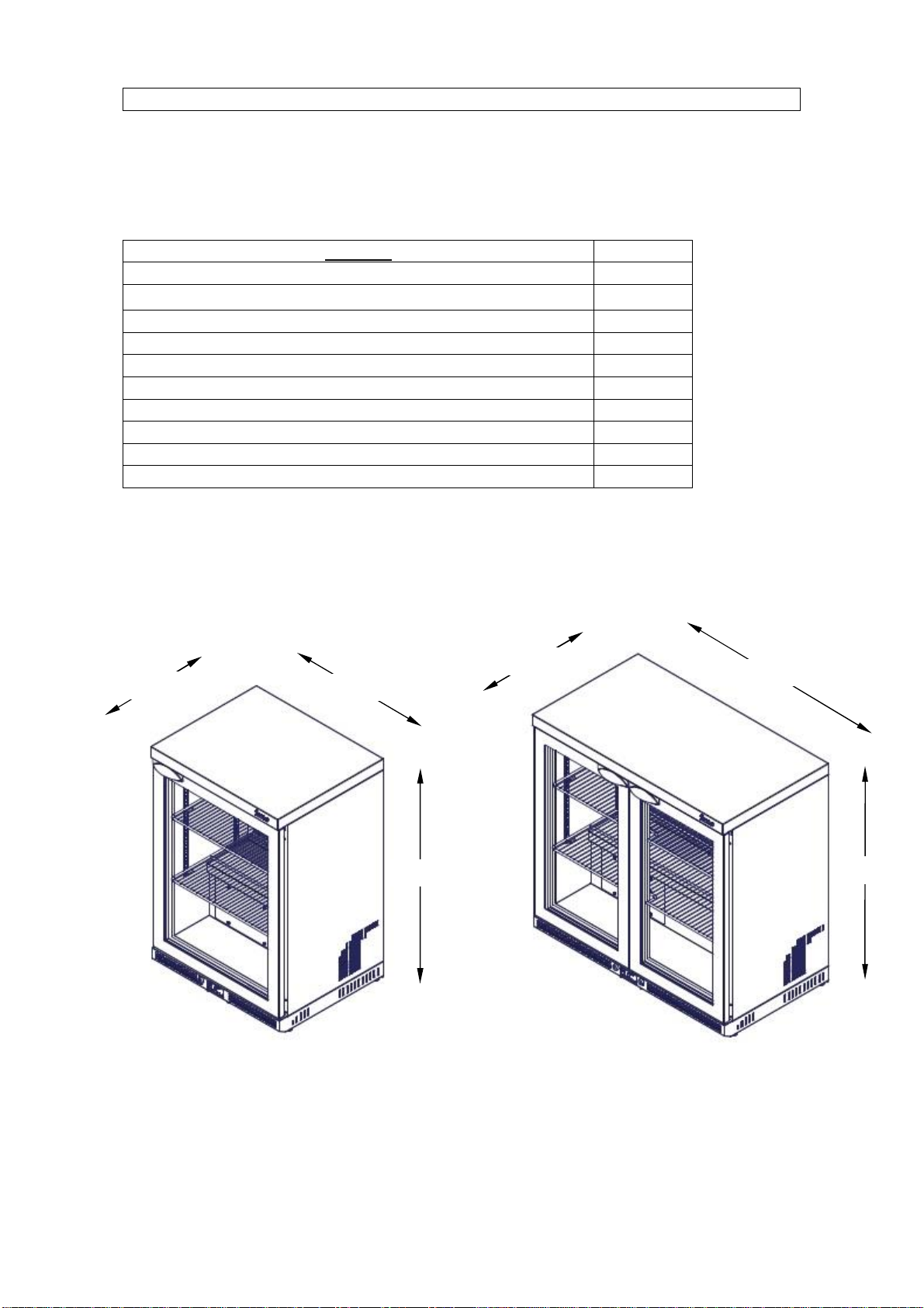
Mistral Dimensions:
MODEL
Y
M
60
STANDARD
900
M60 850 SHORT
850
M60 800 SHORT
800
M
90
STANDARD
900
M90 850 SHORT
850
M90 800 SHORT
800
M135 STANDARD
900
M135 800 SHORT
800
500
mm
Y mm
6
00mm
9
00mm
500
mm
Y
mm
M
60
M
90

Mistral
M
60,
M
90
,
M
135
7
500 mm
Y mm
1350mm
M135
Mistral
M
60,
M
90
,
M
135
8
INSTALLATION
For the Installer
These Instructions contain important information designed to help the user
obtain the maximum benefit from their investment in an IMC Mistral Bottle
Cooler.
Please read them carefully before starting work, and consult with the supplier in
the event of any queries.
Be sure to leave this Instruction Manual with the user after installation of the
machine is complete.
Procedure
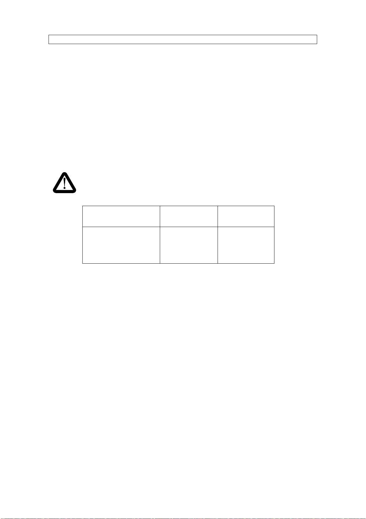
WARNING
The following table shows the weight and the minimum quantity of
people required to lift each unit:
Bottle Cooler Net Weight Quantity of
People
M60 (all variants) 57.5 kg (max) 2
M90 (all variants) 76.5 kg (max) 4
M135 (all variants) 125 kg (max) 4
Install the unit on a flat and level floor.
Ensure a min 10mm clearance either side of the unit, there is to be a min
20mm clearance at the top of the unit and a min 60mm clearance at the
back.
The M135 is supplied on castors to aid installation and cleaning.
Do not install the unit close to a heat source such as a radiator or a warm air
outlet. Ensure that the unit is standing level by adjusting the feet on the base of
the unit.
The unit has an automatic defrost cycle and evaporates all the condensate
water without the need for a drainage system.
NOTE!
The castors on the M135 are to aid installation only. The
machine is not designed to be used as a mobile unit.
It is important to install the Bottle Cooler on a flat surface. This
ensures that the doors are level. Adjustment is provided via the
feet, to enable the installer to level the cabinet.
Engineer Call-outs in order to level Bottle Coolers, will not be
covered under warranty.
Mistral
M
60,
M
90
,
M
135
9
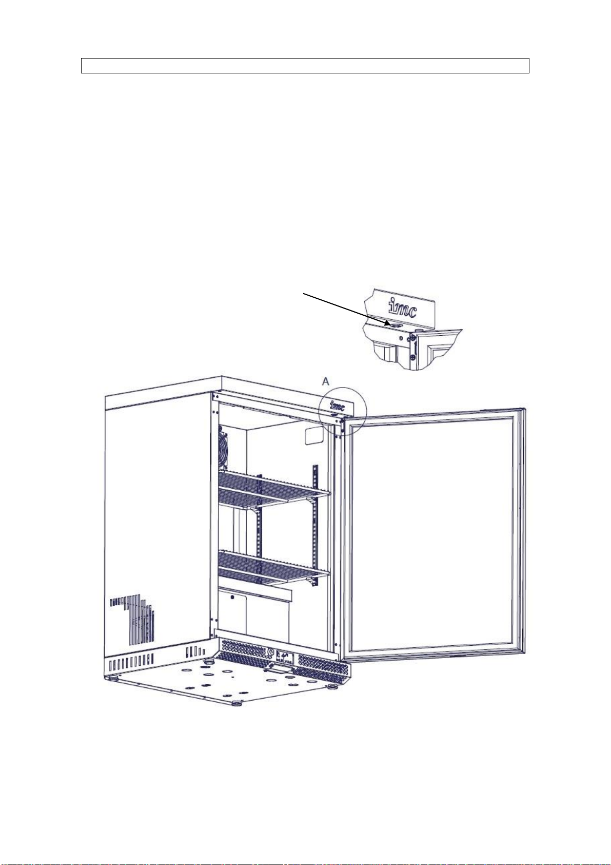
TURNING LED LIGHTS ON-OFF
The cabinet is illuminated by a LED light unit, this light can be turned on or off
by depressing the switch that is located on the underside of the worktop.
To access this switch the door must be opened (the right hand furthest door on
the M90 & M135 units)
When the switch is flush the lights are on.
Light Switch
Mistral
M
60,
M
90
,
M
135
10
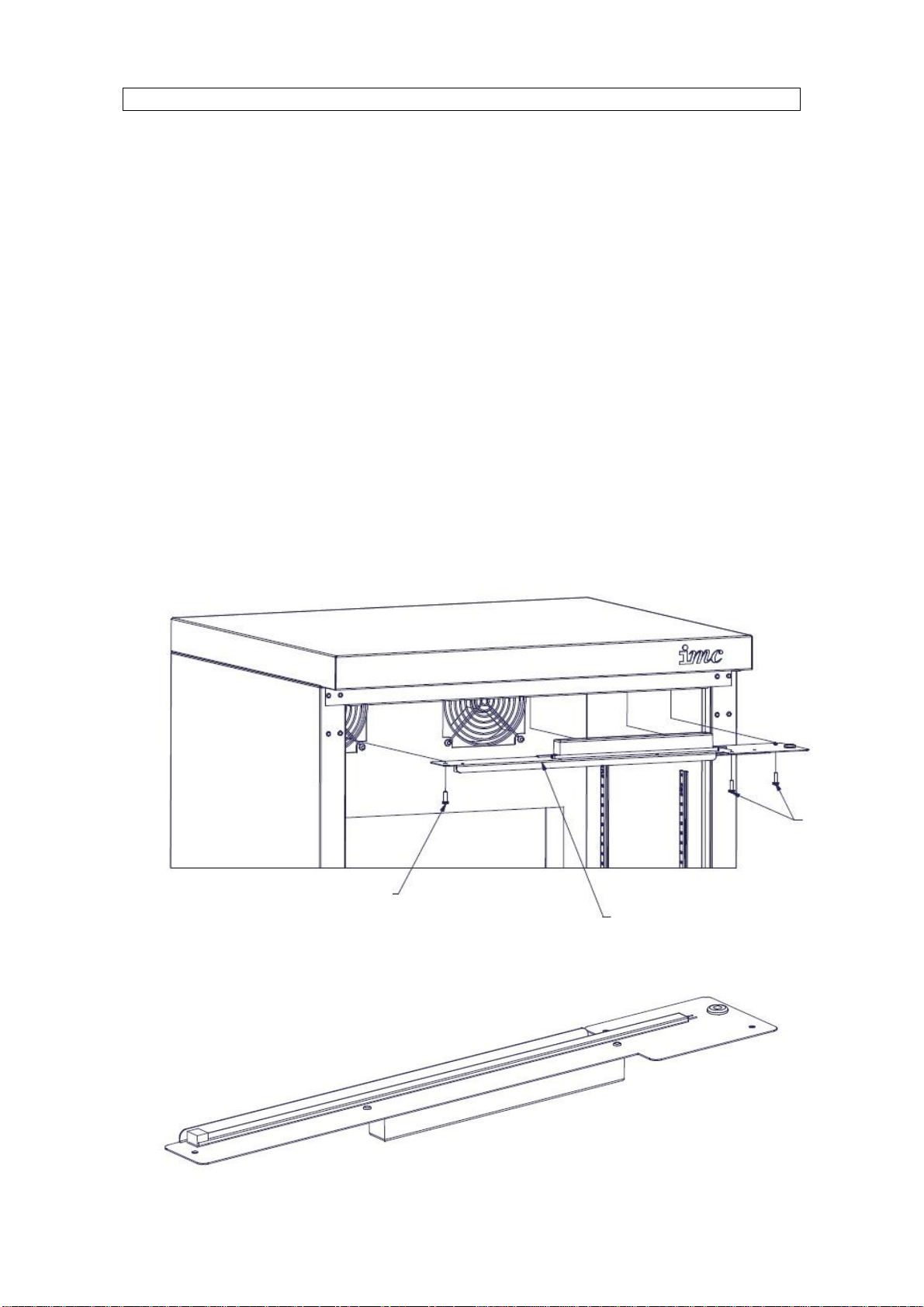
CHANGING A LED LIGHT ASSEMBLY
The cabinet interior is illuminated by a LED light strip fitting located at the front
of the top inner panel.
To change the light assembly:
·Ensure the mains power to the unit has been turned off.
·Open the front cabinet door(s).
·Unscrew the screws holding the LED assembly in place.
·Carefully lower the LED assembly down and disconnect the 2 wires from the
unit.
·The LED light assembly should now be free to fully remove from the unit.
·To fit the replacement unit.
·Place the new LED light assembly inside the unit, re connect the 2 wires
from the unit to the new LED light assembly.
·Re fit the LED light assembly inside the unit by using the screws.
·Re-connect the mains power and ensure the light illuminates by means of
the switch.
Fixing
Screws
Fixing
Screw
s
LED Light
Assembly
crews
LED Light
Assembly
ews

Mistral
M
60,
M
90
,
M
135
11
ELECTRICITY SUPPLY CONNECTION
Position the unit in the chosen site. The electricity supply connection should be
made to a power outlet socket or isolator mounted on the wall close to the
machine. This socket or isolator must be accessible once the machine is
installed. Before connecting, check that the voltage shown on the rating label is
correct for the electricity supply you have available. If the plug does not fit your
sockets or a longer lead is required, changes must be made by an approved
electrician.
NOTE: The plug is fitted with a 10amp fuse.
The plug fuse cover must be refitted when changing the fuse. In the event of
losing the fuse cover the plug must NOT be used until a replacement fuse cover
has been obtained and fitted or the plug replaced.
WARNING: This machine must be earthed
Should the supply cord become damaged then a replacement must be fitted by
an approved electrician. The IEE Codes of Practice must be observed.
The wires in the mains lead are coloured in accordance with the following code
Green and yellow Earth
Blue Neutral
Brown Live
COMMISSIONING
Before using a bottle cooler for the first time, the interior should be wiped out
with a clean damp cloth.
Allow the machine to stand for 1 hour to allow the refrigerant to settle. Plug in
and switch on at the wall socket. There is no separate switch to turn on the
machine. The compressor will start running less than one minute after the
supply is switched on.
Check that the light is working, and check the switch is operating correctly.
Run the unit empty, and check that cold air is being circulated within the
cabinet.

Mistral
M
60,
M
90
,
M
135
12
CHANGING THE CONTROLLER SET POINT
The electronic temperature controller is factory set to 4°C and will cycle the air
temperature between 2°C and 6°C. The set point can be adjusted between 0°C
and 10°C by following the button sequence below:
USING YOUR BOTTLE COOLER
This unit is for cooling bottles and cans only. Do not load the cabinet with boxed
goods as this prevents air circulation and the goods will not cool down as
quickly. While loading ensure that the interior grilles are not obstructed by the
bottles.
Do not place hot or warm goods in the cabinet. Only goods at room
temperature or less should be placed in the unit, otherwise performance will be
affected. It is recommended that the cabinet is stocked after closing at night or
first thing in the morning to allow time for the bottles to cool. Ensure that stock
is rotated by placing new stock at the back of shelves or in one side of the
cabinet to ensure that colder bottles are served first.
Do not leave the doors open when the unit is running as this causes the
evaporator to ice up, preventing the unit from operating efficiently.
Ensure that the front grille is always unobstructed.
1)
Use the UP and DOWN buttons, to scroll to the
desired set point temperature (min 0°C, max 10°C)
2)
6
Press
SET
button
to accept
3)
4
4)
Press SET button and the current set point
temperature will be displayed
5
Then press stand-by button to esc.
Display will revert back to current
internal air temperature
4
Press SET the current SET Point will be displayed, if
Loc is displayed then the controller is locked, to
unlock press and hold the SET button for 3 seconds,
UnL will then be displayed

Mistral
M
60,
M
90
,
M
135
13
CLEANING
Clean doors and surfaces as required, occasionally remove all merchandise
and clean interior surfaces with a clean damp cloth.
DO NOT USE CLEANING MATERIALS CONTAINING ABRASIVES OR
BLEACHES.
In the case of heavy soiling use a mild liquid detergent. The unit can be
washed on the inside using bicarbonate of soda to remove stale smells.
CHANGING SHELF POSITION
The shelves in all Mistral units are fully adjustable. To adjust the shelves:
·Remove the shelf.
·Unclip the shelf supports as shown below.
·Hook the shelf supports in the required location.
·Ensure all shelf supports are at the same height for a level shelf. The
support strips are numbered to aid positioning.
·Replace the shelf.
·On the shelves in the M135 ensure that the clips are in position on the front
covering the join (it should be a tight fit if not squeeze the clip slightly to give
a better fit)
Extra shelves are available from IMC.

Mistral
M
60,
M
90
,
M
135
14
MAINTENANCE
Warning
Never service, repair or troubleshoot a unit unless you are a
professional air conditioning / refrigeration service person. Improper
servicing can lead to serious injury or death from fire, electric shock or
explosion.
Remove the service panel and insulation block inside the cabinet after
switching the unit off from the mains supply. Clean the compressor coil
with a brush and vacuum cleaner. THIS MUST BE DONE every three
months or when dirty (whichever is sooner). Re-fit the insulation and
service panel and secure with the original screws. Once the service panel
has been re-fitted clean the grille at the bottom front of the cabinet. Re-
connect the power supply and check that unit returns to normal operation.
Service / access
panel

Mistral
M
60,
M
90
,
M
135
15
Other than regular cleaning the unit requires no maintenance by the end user. It
is recommended that the unit is serviced by an IMC approved engineer at least
once a year.
Details of IMC Service Contracts are available on application.
DO’S AND DON’TS
Do Install on a level surface.
Do Ensure plug is accessible with the unit installed.
Do Regularly clean the condenser and compressor.
Do Rotate stock of bottles.
Don’tSit or stand on the unit worktop.
Don’tLoad with boxed goods.
Don’tLeave the doors open.
Don’tCover the shelves with any protective materials which may obstruct air
circulation through them.
Don’tInstall unit in direct sunlight.
Don’tBlock the air inlet grilles.
Don’tStore food in the unit.
Don’tPlace hot or warm goods in the unit.
Don’tUse the unit outside.

Mistral
M
60,
M
90
,
M
135
16
ORDERING SPARE PARTS
In the event that spare parts or accessories need to be ordered, please always
quote the SERIES AND SERIAL NUMBER of the machine. This is to be found
inside the cabinet.
For installations outside the UK please contact your supplier.
For information on IMC spares and service support (if applicable), please call
IMC on +44 (0)1978 661155. Alternatively, contact us via email or fax:
IMC Service Desk Fax: +44 (0)1978 667766
E-mail: service@imco.co.uk
IMC Spares Desk Fax: +44 (0)1978 667759
E-mail: spares@imco.co.uk
END OF LIFE DISPOSAL
At the end of its useful life the unit must be disposed of correctly and safely, to
meet the requirements of EU legislation regarding the recovery of ozone
depleting substances. The unit must be sent to a specialist recovery, recycling
and disposal site that is licensed for the disposal of refrigerated equipment.
Please note that the insulation in the Mistral range does not contain any ozone
depleting substances. The refrigerant used in the Mistral M60, M90 and M135
is R290a.
IMC can arrange removal of your redundant bottle coolers, transfer to safe
storage and disposal.
For more information contact IMC sales department.
Call +44 (0)1978 661155 Alternatively Email: sales@imco.co.uk
MATERIAL CONTENT
The Mistral units may contain a combination of the following materials;
Metals Stainless Steel, Mild Steel (inc. Nickel Plated, Chrome
Plated & Zinc Plated), Aluminium and Copper
Plastics & Rubber PVC, Nylon, Polypropylene, Polycarbonate, Polyester,
Acetate, Neoprene Rubber and Silicone Rubber
Insulation Polystyrene, Polyurethane Foam
Oils & Gases Ester oil, Refrigerant R290a
Other Glass, Magnesium Oxide, electronic components.
Mistral
M
60,
M
90
,
M
135
17
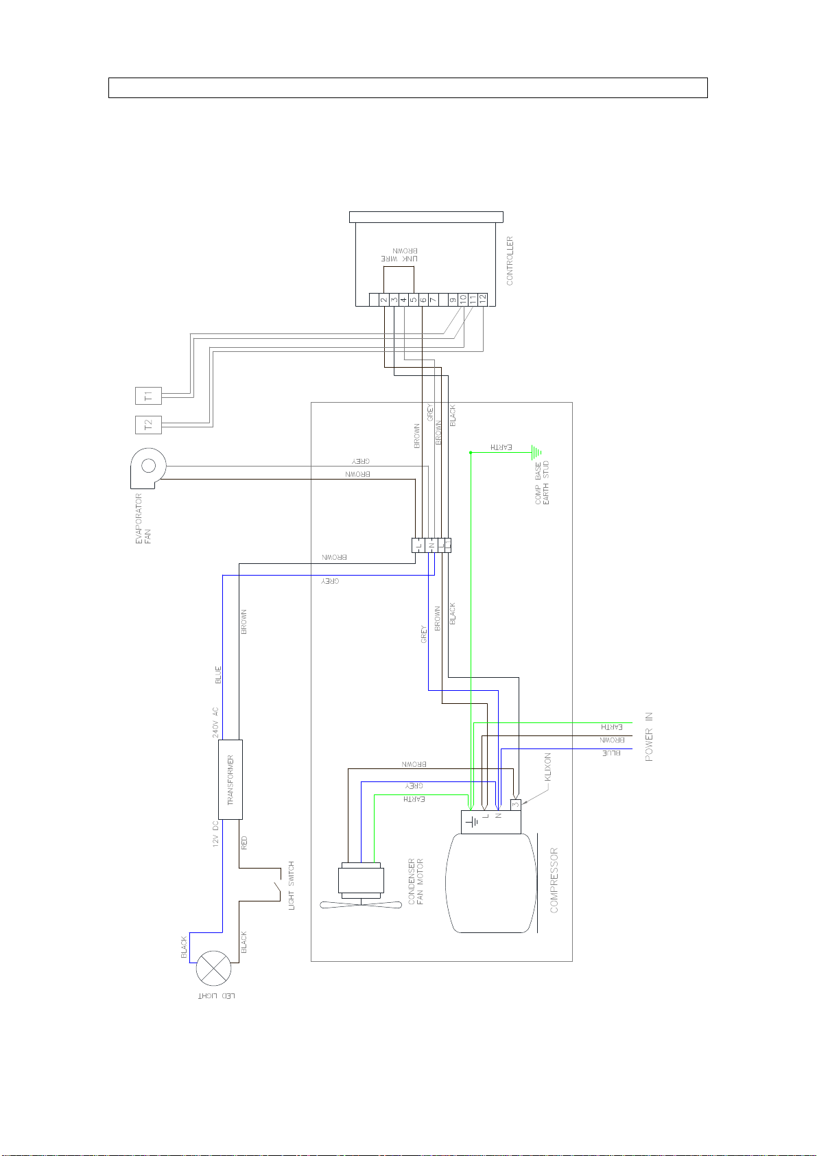
M60 WIRING DIAGRAM

Mistral
M
60,
M
90
,
M
135
18
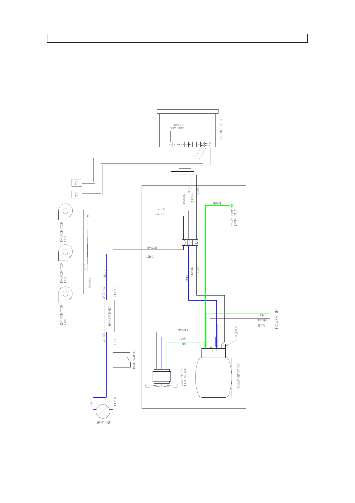
M90 WIRING DIAGRAM
Mistral
M
60,
M
90
,
M
135
19
M135 WIRING DIAGRAM
Mistral
M
60,
M
90
,
M
135
20
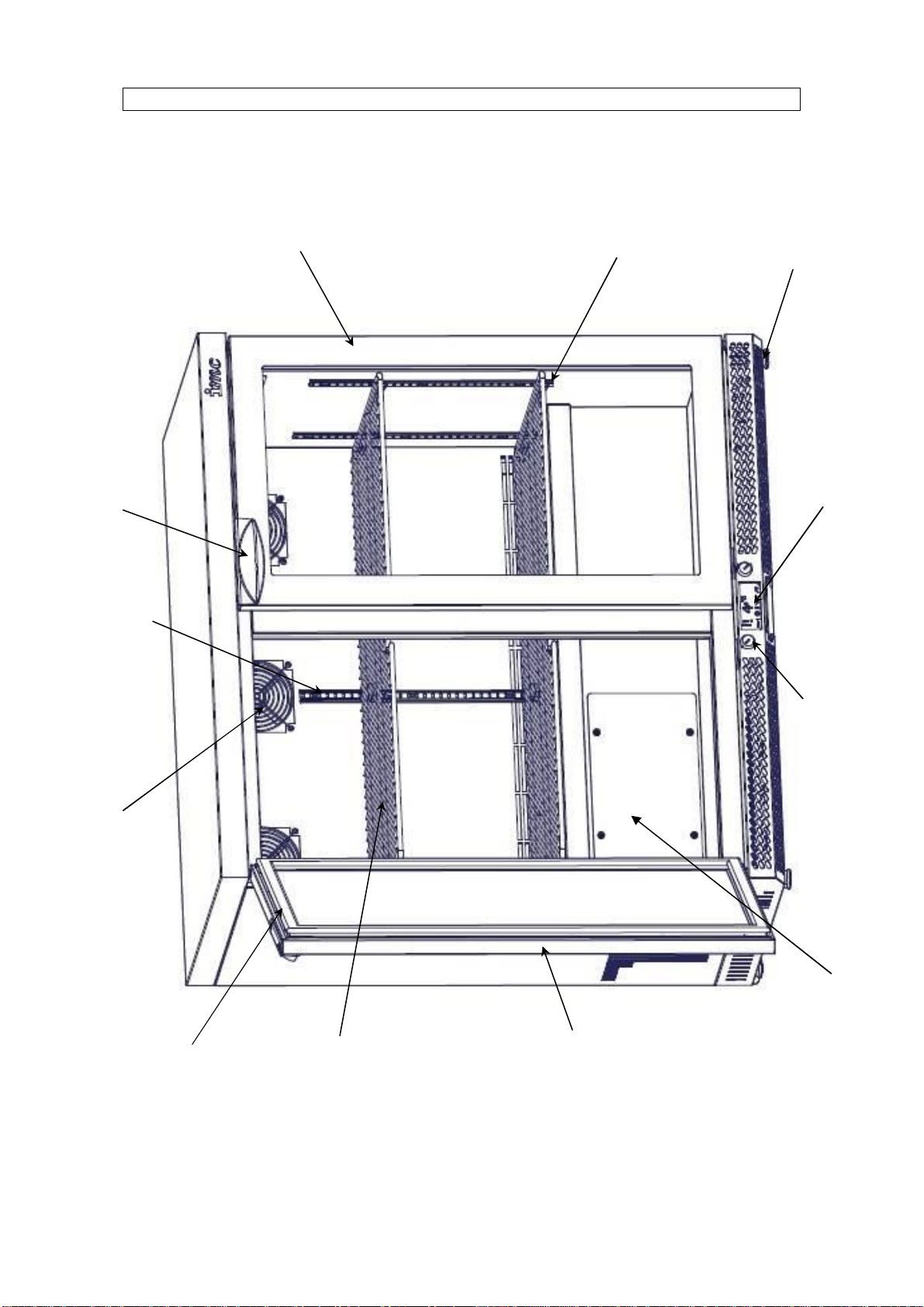
SPARES IDENTIFICATION FRONT
Access Panel
Electronic
Controller
Lock
Shelf Clip
Pilaster Strip
Door
Gasket
Evaporator Fan
Handle
Shelf
RH
Door
Glider Foo
t
LH Door
This manual suits for next models
3
Table of contents
Other IMC Accessories manuals

Popular Accessories manuals by other brands

Bosch
Bosch RADION installation guide

Wenglor
Wenglor P1HJ1 Series operating instructions

Technische Alternative
Technische Alternative RAS+DL Operation, Programming, Installation Instructions

Armstrong Monitoring
Armstrong Monitoring AMC-1222 instructions

QOLSYS
QOLSYS IQ SHOCK-S Quick install guide

epico
epico EPI-NA-PB-MU46 manual

 Specifications")


