IMC Inlet Station User manual

A34/060 –R1
February 2016
Page | 1
Inlet Station & Remote Dewaterer
INSTALLATION MANUAL
IN L E T ST A T I O N &RE M O T E DE W A TE R E R
SAVE THESE INSTRUCTIONS FOR FUTURE REFERENCE
CONSERVEZ CES INSTRUCTIONS POUR RÉFÉRENCE ULTÉRIEURE
P a g e | 2February 2016 A34/060 –R1
Inlet Station & Remote Dewaterer
EC DECLARATION OF CONFORMITY
(Guarantee of Production Quality)
We, Imperial Machine Company Limited of:
Unit 1, Abbey Road, Wrexham Industrial Estate, Wrexham, LL13 9RF
Declare under our sole responsibility that the following machines; Food Waste Disposers, Impactor Range, Potboy,
WastePro, WastePro II, WasteStation, Burnishers, Composters, Inlet Station, Remote Dewaterer and
Bench systems
As described in the technical construction file (TCF) documentation, are in conformity with the protection
requirements of the Electromagnetic Compatibility Directive 2004/108/EC.
These products are manufactured in accordance with harmonised standards EN 61000-6-1: 2001 Immunity and EN
61000-6-3: 2001 Emissions.
They also satisfy the essential health and safety requirements of the Low Voltage Directive 2006/95/EC, EN60204-1
Safety of Machinery and are manufactured in accordance with product specific standards including BS EN 60335-1,
BS EN 60335-2-16 and BS EN60335-2-64.
Approved by
Eddy Plumb
Engineering Manager
Signed at Wrexham, Date
12/10/2016

A34/060 –R1
February 2016
Pag e | 3
Inlet Station & Remote Dewaterer
CONTENTS
1.0
INTRODUCTION....................................................................................................................................... 4
2.0
MODEL IDENTIFICATION ......................................................................................................................... 5
3.0
INSTALLATION REQUIREMENTS & SPECIFICATIONS................................................................................. 7
3.1
ELECTRICAL: .......................................................................................................................... 7
3.2
WATER/WASTE:..................................................................................................................... 7
3.3
DIMENSIONS
&
WEIGHT:........................................................................................................ 7
4.0
SAFETY INSTRUCTIONS............................................................................................................................ 8
5.0
INSTALLATION......................................................................................................................................... 9
5.1
S
ELECTION
O
F
S
ITE
/P
OSITIONING
&
C
LEARANCES
............................................................................ 10
5.2
W
ASTE
O
UTLET
C
ONNECTION
..................................................................................................... 12
5.3
W
ATER
I
NLET
S
UPPLY
C
ONNECTION
.............................................................................................. 13
5.4
E
LECTRICAL
C
ONNECTION
........................................................................................................... 14
5.5
E
QUIPMENT
C
OMMISSIONING
-
P
RE
S
TART
C
HECKS
.......................................................................... 17
P a g e | 4February 2016 A34/060 –R1
Inlet Station & Remote Dewaterer
1.0 INTRODUCTION
This manual is applicable to the Installation of the Inlet Station & Remote Dewaterer
models, IMC Order No’s:
F79/030 Inlet Station, 400 volt, 3-phase, 50 Hz
F78/060 Remote Dewaterer, 400 volt, 3-phase, 50 Hz
Thank you for your confidence and congratulations on your purchase of our WasteStation
technology; this demonstrates a true understanding and commitment to the need for waste
food recycling and environmental sustainability. Not only are we pleased to partner directly
and indirectly through our network of trusted distributors from around the world, we are
especially pleased to know that you have selected IMC as your chosen vendor of choice. IMC
is proud to lead the way in terms of ‘green technology’and to know that together, we can
make an important difference in the global war against waste.
The IMC Inlet Station & Remote Dewaterer are intended for the processing of food waste
matter by maceration under an automatic water flow, dewatering of the macerated food
waste and discharge of the dewatered food waste into a receptacle. The ‘grey’water will be
discharged into the drainage system according to local regulations where applicable and
under responsibility of the installer.
ON DELIVERY
The chosen IMC system is supplied with the following ancillary items.
ITEM QTY
Fully assembled Waste Appliances 1
Release Key 1
Feeding Pusher 1
Waste Bin (240 ltr) 2
Instruction Manual 1
Operating Plaque (wall mounted self-adhesive) 2
Appliance Hoses (flexible plastic) 3
Waste Outlet Pipe (2”plastic, rigid) 1
The Inlet Station system is supplied with the following additional Cables for integration:
DESCRIPTION PART NO TYPE QTY
Dewaterer
Motor
Supply Cable G60/809 4 x 1.5mm² 1
Starter Box to
Junction Box Link G60/805 12 x 0.75mm² 1
Controller Box Link
Cable G60/810 8 x 1.00mm² 1
Note: These cables are already connected at the INLET STATION, but require connection at
the REMOTE DEWATERER (junction box). Refer to Section 5.4.4 for instructions.

A34/060 –R1
February 2016
Pag e | 5
Inlet Station & Remote Dewaterer
Please ensure the appliance and ancillary contents are complete and not damaged. Notify
both the Carrier and Supplier immediately if there is a shortage or if an item is damaged.
2.0 MODEL IDENTIFICATION
The IMC Inlet Station & Remote Dewaterer grey water macerator appliances are for use in
Commercial establishments only and are for permanent connection.
The IMC Inlet Station is a single unit enclosing all components for the maceration and
pumping of food waste.
IMC
INLET STATION
The Inlet Station comprises of the control cabinet, Macerator and Pump assemblies.
The Remote Dewaterer comprises of a cabinet with a dewaterer unit and removable 240 litre
wheeled waste bin.

P a g e | 6February 2016 A34/060 –R1
Inlet Station & Remote Dewaterer
IMC REMOTE DEWATERER

A34/060 –R1
February 2016
Pag e | 7
Inlet Station & Remote Dewaterer
3.0 INSTALLATION REQUIREMENTS & SPECIFICATIONS
The Inlet Station and Remote Dewaterer require the following electrical and mechanical
services for installation
3.1 ELECTRICAL:
Voltage/Frequency: 400V, 3PH, 50 Hz
Total Power: 4.1 kW (5.49 hp)
The Inlet Station and Dewaterer system contains the following rated motors:
F
UNCTION DESIGNATION MOTOR POWER
Macerator M1 2.2 kW / 3.0 hp
Auger M2 1.1 kW / 1.5 hp
Pump M3 0.75 kW / 1.0 hp
3.2 WATER/WASTE:
Water Supply: Pressure - 6 bar (maximum) (87 psi)
Flow Rate (dewaterer) - 12 –15 Litres /min (2.6–3.3 gpm)
Flow Rate (Inlet Station) - 18 –30 Litres /min (5.9 –6.6 gpm)
(Flow is Installation Dependant for Inlet Station)
Temperature - 15 - 50°C (59 - 86°F)
Waste: Minimum 2”Diameter waste Outlet is required
3.3 DIMENSIONS & WEIGHT:
A. Inlet Station:
Weight: - 102 kg (225 lb)
Dimensions (w x d x h): - 700 x 771 x 900 mm (27.56 x 30.35 x 35.43 inches)
B. Remote Dewaterer:
Weight: - 167 kg (without Bin) (368 lb)
Dimensions (w x d x h): - 839 x 1055 x 1776 mm (33.03 x 41.53 x 69.92 inches)
P a g e | 8February 2016 A34/060 –R1
Inlet Station & Remote Dewaterer
4.0 SAFETY INSTRUCTIONS
All safety instructions detailed within this document are to be adhered to for safe operation,
installation and maintenance of personnel and the equipment.
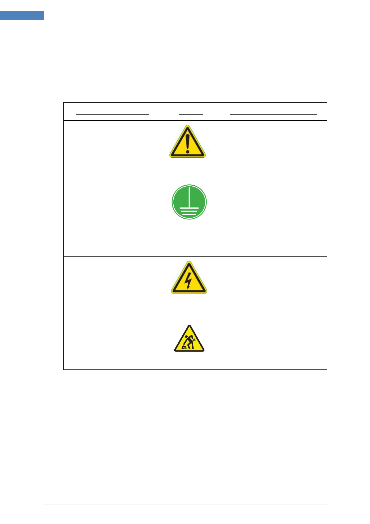
The following symbols are used on the product and throughout the product documentation:
MEANING / DESCRIPTION SYMBOL SIGNIFICATION / DESCRIPTION
W
ARNING
/C
AUTION
An appropriate safety instruction
should be followed or caution to
a potential hazard exists.
A
VERTISSEMENT
Une consigne de sécurité
appropriée doivent être suivies ou
garde d'un danger potentiel existe.
P
ROTECTIVE
E
ARTH
(G
ROUND
)
To identify any terminal which is
intended for connection to an
external conductor for
protection against electric shock
in case of a fault, or the terminal
of a protective earth (ground)
electrode.
T
ERRE DE
P
ROTECTION
Pour marquer bornes destinées à
être raccordées à un conducteur de
protection extérieur contre les
chocs éclectiques en cas de défaut
d’isolement, ou pour marquer la
borne de la terre de protection
D
ANGEROUS
V
OLTAGE
To indicate hazards arising from
dangerous voltages.
T
ENSION DANGEREUSE
Pour indiquer les dangers résultant
des tensions dangereuses.
H
EAVY
This product is heavy and
reference should be made to the
safety instructions for provisions
of lifting and moving.
L
OURD
Ce produit est lourd et se référer
aux instructions de sécurité pour les
dispositions de soulever et
déplacer.
·This product is to be installed by a qualified IMC appointed installation engineer observing
all local and regional codes.
·All electrical and water services are to be isolated and locked out before installation or
carrying out any remedial work to the IMC Waste appliance.
·Ensure all water supply and waste connections are tight.

A34/060 –R1
February 2016
Pag e | 9
Inlet Station & Remote Dewaterer
5.0 INSTALLATION
PRIOR TO CARRYING OUT ANY WORK, ENSURE BOTH ELECTRICAL AND OTHER
SUPPLY SERVICES ARE ISOLATED
Installation of the appliance MUST be carried out in the following chronological order:
A. Selection of site and positioning
B. Waste outlet connection to the main drain.
C. Water Inlet supply connection.
D. Electrical Connection.
E. Commissioning Tests and necessary adjustments. Including:
i. Check for correct rotation of pump and Dewatering Unit drive motors
ii. Check for correct operation of magnetic feed hopper interlock device
iii. Check for correct operation of bin present sensor
iv. Check for correct operation of bin level sensor
v. Check for correct operation of Emergency-Stop push button
F. Refit all panels
G. Fix self-adhesive Operator instruction plaques in a prominent position adjacent to
both machines.
P a g e | 1 0 February 2016 A34/060 –R1
Inlet Station & Remote Dewaterer
5.1 Selection Of Site/Positioning & Clearances
Select the site of the Inlet Station with care so that it is convenient both for the major source
of food waste and for access by machine operators.
The machine should be installed as close to the existing drains as reasonably practicable.
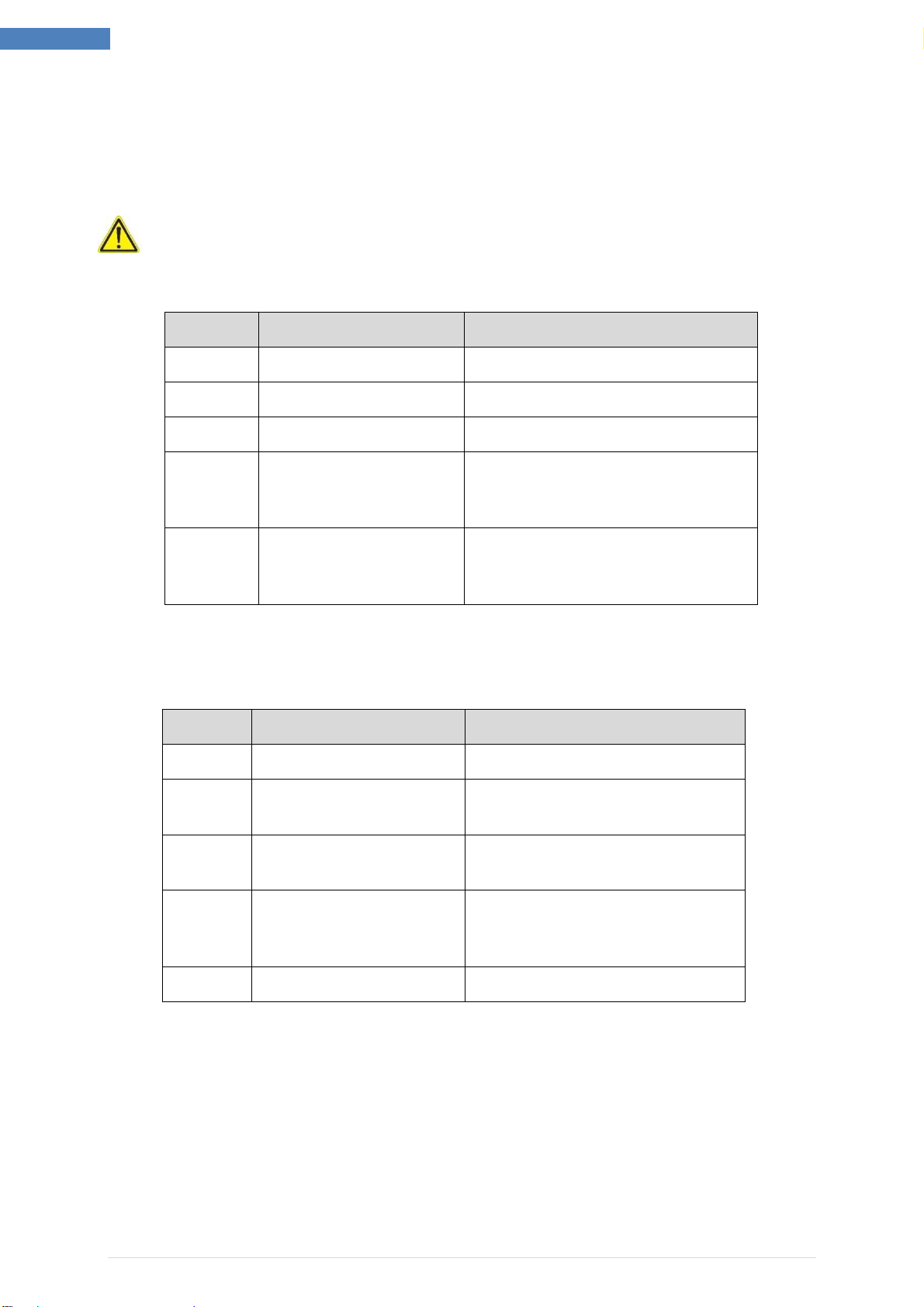
5.1.1 The IMC Waste Appliances require the following minimum clearances:
A. Inlet Station Appliance System
POSITION
CLEARANCE
REASON
TOP
11
00 mm
/
36
inches
For operating the machine.
LHS
600 mm
/
24 inches
For service access if
available*.
RHS
600
mm
/
24
Inches
For service access if available*.
FRONT
900
mm
/
3
6 inches
ensure that the control buttons and
the emergency stop button are easily
accessible on the front panel
REAR
200
mm
/
8
inches
Clearance for waste outlet, water
inlets
and electrical connection (including
isolator switch).
B. Remote Dewaterer Appliance System
POSITION
CLEARANCE
REASON
TOP
30
0
mm
/
12
i
nches
Access to pipework
.
LHS
600 mm
/
24 inches
For service access if available*.
RHS
60
0 mm
/
24
Inches
For service access if available*.
FRONT
1
00
0
m
m
/
39
inches
ensure that
bin access
and the
emergency stop button are easily
accessible on the front panel
REAR
30
0
mm
/
12
inches
For service access if available*.

A34/060 –R1
February 2016
Pag e | 1 1
Inlet Station & Remote Dewaterer
5.1.2 The IMC Waste appliances require a minimum, 2 persons and the appropriate lifting
equipment to position at the site of installation.
The IMC Waste appliances can be positioned near to the final place of installation on
its shipping pallet, using a pallet truck.
A hoist, forklift or other appropriate lifting equipment will be required to lift the
machine off the pallet and onto the floor, in its final resting position.
5.1.3 Adjust height and level of the appliances accordingly and lock into place.
A minimum of 100mm (4 inches) is required underneath the Inlet Station or Remote
Dewaterer cabinets.

P a g e | 1 2 February 2016 A34/060 –R1
Inlet Station & Remote Dewaterer
5.2 Waste Outlet Connection
The IMC waste appliances are fitted with a standard 51 mm (2”) waste pipe stub outlet for
connection to the dedicated waste drain.
The IMC Waste outlet is located at the Rear of the Remote Dewaterer unit.
THE FOLLOWING ARE IMPORTANT INSTALLATION REQUIREMENTS
·The size of these outlets must not be reduced, and the drainpipe should run into
51mm (2”) outside diameter pipe work as far as its junction with the main drain line
connection.
·The length of run between the machine and the main junction must be kept to an
absolute minimum.
·The waste pipe must have a gradient fall of at least 1 in 7 (-8° / 14.29% grade).
·It is recommended that when required, a running trap be fitted. (see photo below)
“P”type, “S”type or bottle traps MUST NOT be used.
·Changes of direction should be made by swept bends rather than elbows.
·Cleaning eyes should be considered and fitted where possible.
·IMC recommends the use of copper water pipe and compression fittings along with
standard ABS/PVC drain line connections with compression fittings.
·All water and drain line connections should be installed according to local codes and
regulations.
·IMC Waste appliances must have an independent waste pipe, which does not also
serve sinks, dishwashers and similar equipment.
·The use of Grease Traps is determined in accordance with local codes and
regulations; any such device must be regularly maintained and is the responsibility of
buyer.
·If this outlet is positioned below a control box, it is important to use fittings, which
give at least the minimum 220mm (8.7”) clearance, required for service access.

A34/060 –R1
February 2016
Pag e | 1 3
Inlet Station & Remote Dewaterer
5.3 Water Inlet Supply Connection
THE FOLLOWING ARE IMPORTANT INSTALLATION REQUIREMENTS
Hot and Cold Water Inlet Supplies
The plumbing system is to be installed and used in accordance with the requirements of the
Water Supply (Water Fittings) Regulations and Byelaws. The purpose of these regulations is
to protect your drinking water supply from contamination.
When the WasteStation is purchased with a cold water air break, customers are to ensure
that the HOT water supply is compliant and has an approved air break or back flow
prevention.
By-laws and Regulations vary by region so it is important to check with the authority having
jurisdiction in your area.
The rate of water flow required for normal food waste is 18 - 30 litres (5.9 - 6.6 gallons UK)
per minute, at a maximum pressure of 6 bar. This flow is entirely dependant upon the
installation type / length. IMC will provide advice on this.
The head of water should not be less than 0.18 bar (1.8m) (18 kPa).
The IMC Inlet Station is provided with 2 x ¾”Appliance connections for the Cold water supply
at the rear of the machine.
The IMC Remote Dewaterer is provided with 1 x ¾”Appliance connections for the Hot water
supply at the rear of the machine.
An isolation valve should be fitted, to enable the installer to both isolate for maintenance
and adjust the flow of the hot and cold water supplies.
It is recommended that a constant water pressure and flow rate should be available at all
time during operation.
5.3.1 Connect appropriate hoses to the water inlet connections. Ensure they are not
routed to hinder access to the Isolator and that they do not present a hazard.
5.3.2 Open water supply isolator valves slowly.
5.3.3 Ensure that there are no leaks evident.
5.3.4 Isolate the water supply.
P a g e | 1 4 February 2016 A34/060 –R1
Inlet Station & Remote Dewaterer
5.4 Electrical Connection
·ALL ELECTRICAL WORK MUST BE CARRIED OUT BY A QUALIFIED
ELECTRICIAN AND IN ACCORDANCE WITH LOCAL ELECTRICAL CODES
AND PRACTICES.
·THE IMC Inlet Station or Remote Dewaterer must be grounded
·The Inlet Station or Remote Dewaterer Appliances must be
protected by a 3-Pole Branch Circuit breaker rated 16A
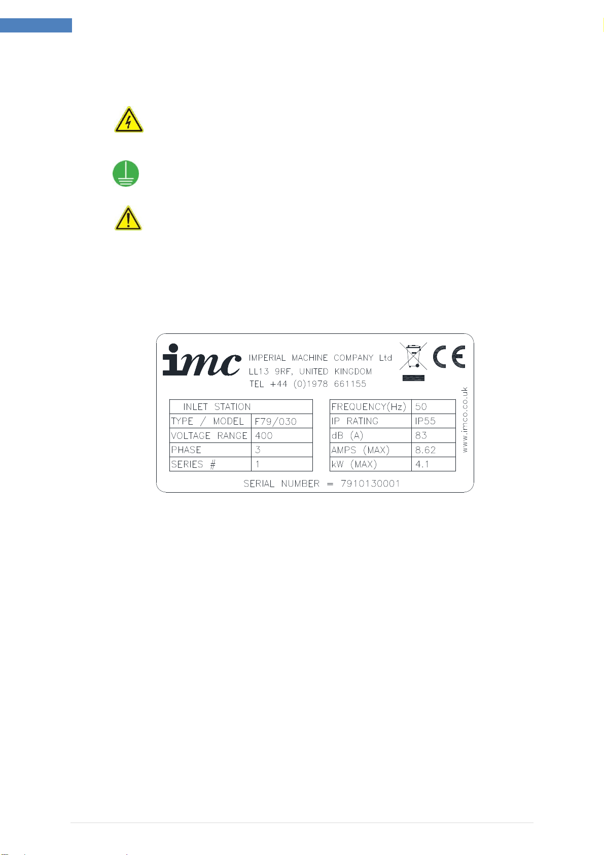
Examine the rating plates attached to the machine to ensure that the characteristics shown
are correct for the supply available. The rating plate is located on the rear of the machine; a
representative sample is shown below.
The Inlet Station or Remote Dewaterer is for permanent connection and is rated 400V 3PH,
50Hz, 4.1kW (16A) as a connected system. The machine is not for continuous use (duty cycle
30%).
5.4.1 Ensure both the electrical and water supplies are isolated.
5.4.2 A mains cable of 4 x 1.5mm² including ground conductor of type 3184Y 300/500V to
BS6500 must be used.
5.4.3 Run the mains cable to the mains isolator switchbox on the rear of the Inlet Station
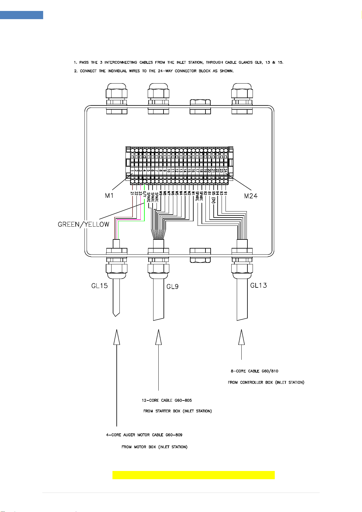
and connect as shown in figure 3.
Run the 3 interconnecting cables from Inlet Station to the Junction Box on the
Remote Dewaterer. Connect these 3 cables as described in figure 4.

A34/060 –R1
February 2016
Pag e | 1 5
Inlet Station & Remote Dewaterer
Figure 3 - Inlet Station Mains cable connection at the isolator switch on the
rear panel of the machine.
5.4.4 The Inlet Station system comprises of interconnecting cables that are supplied with
the system to power and interface with the Remote Dewaterer.
Refer to Figure 4 for the Inlet Station power and interface connection.
5.4.5 On completion of electrical connection and prior to equipment testing, check for
proper rotational direction of motors as detailed in section 5.5 of this guide.
TYPE 3184Y, 4 x 1.5mm
²
L1
L2
L3
PE
P a g e | 1 6 February 2016 A34/060 –R1
Inlet Station & Remote Dewaterer
Figure 4 - Inlet Station > Remote Dewaterer Interconnection Diagram

A34/060 –R1
February 2016
Pag e | 1 7
Inlet Station & Remote Dewaterer
5.5 Equipment Commissioning - Pre Start Checks
Following Installation carry out the following commissioning operations:
5.5.1 Check that all Electrical supply connections are correctly made and securely fixed.
5.5.2 Check that nothing has been left in the macerator chamber and that the macerator
rotor is free to rotate (use the release key if necessary).
5.5.3 Fit the hopper baffle plate and ensure that the magnetic safety interlock knob is fully
screwed down (Do not over tighten).
5.5.4 Check that the Emergency Stop button is in the correct ‘OUT’position –(Turn and
release)
5.5.5 Turn on the hot and cold water supplies (Cold (2 off) to Inlet Station, Hot to Remote
Dewaterer).
Check that there are no water leaks.
5.5.6 Turn on the Electrical supply and set the Inlet Station Isolator to “ON”.
5.5.7 Put the waste bin in place in the Remote Dewaterer Bin Area –push all the way back
and check that the solid red light goes out.
5.5.8 When machine is ready to operate, all lights on the operator control panel should be
extinguished.
5.5.9 The motor should now initially be checked for rotational conformance.
Macerator Motor –controlled by the PLC and to help prolong the life of the
macerator cutting edge, the macerator will rotate in
reversed direction each time the WasteStation is used.
Motor rotation in this instance does not matter. No motor
rotation check is necessary.
Pump Motor –Ensure the pump motor rotates according to the directional
arrow. Wrong direction of pump rotation will result in the
feed hopper not draining and possibility of splash back of
water and food waste from the feed hopper.
Dewatering Unit –Ensure the dewatering unit drive motor rotates according to
the directional arrow. Wrong direction of the motor will
result in faulty machine function and damage to the
machine.
5.5.10 Run a test Cycle, check operation of Emergency Stop.
5.5.11 Reset Emergency Stop, System should reset after running a dewatering cycle.
5.5.12 Refit all panels
The Waste System is now ready to operate.

P a g e | 1 8 February 2016 A34/060 –R1
Inlet Station & Remote Dewaterer
This manual suits for next models
3
Table of contents
Other IMC Cleaning Equipment manuals

Popular Cleaning Equipment manuals by other brands

JBM
JBM 53650 instruction manual

MACKISSIC
MACKISSIC MIGHTY MAG VMS25 Safety & Operating Instructions

Graymills
Graymills TL-Series Operation and maintenance instructions

Vax
Vax Home SpotWash Series user guide

Flexin
Flexin 230152 installation guide

Hugh Crane
Hugh Crane COMMANDO operating & maintenance manual


