B-TEC UD-800 Product guide

B-TEC GmbH • Zunftweg 6-8 • D-31303 Burgdorf / Ehlershausen • Tel.: +49(0)5085-97100-0
Fax: +49(0)5085-97100-30 • Email: info@btecsystems.de • www.btecsystems.de
ud-800
Washer Combination for
Water Based Paint or Solvent
Operating Manual and Test Log Book
for Spray Gun Cleaning System ud-800
–Translation of German Original Document –

B-TEC GmbH • Zunftweg 6-8 • D-31303 Burgdorf / Ehlershausen • Tel.: +49(0)5085-97100-0
Fax: +49(0)5085-97100-30 • Email: info@btecsystems.de • www.btecsystems.de
EU Declaration of Conformity according to DIN EN ISO/IEC 17050-1
Manufacturer:
B-TEC GmbH
Zunftweg 6-8
31303 Burgdorf / Ehlershausen
Germany
Herewith, we declare that the machines and marketed models described in the following conform in
conception and in design to the relevant fundamental safety and health requirements of the applicable
directives. This object of conformity is issued under the sole responsibility of the manufacturer. The
object of the declaration is in conformity with the relevant Union harmonisation legislation.
If you modify the machine without our explicit agreement, this declaration will be invalidated.
Product type:
Spray gun cleaning system
Type designation:
ud-800
Serial number:
______________________
Date of construction (month/year):
___________
This machine has been designed in accordance with the following regulations:
Machine directive 2006/42/EC
ATEX directive 2014/34/EU
Registered with: PTB 0102 / R.No.: 05 ATEX D 116
ATEX description:
II 2G Ex h IIB T6 Gb
The following harmonised technical standards have been applied:
Safety of machinery:
DIN EN ISO 12100
Machines for surface cleaning and pre-treatment of industrial
items using liquids or vapours
- Part 1: Common safety requirements:
- Part 2: Safety of machines using water based cleaning liquids:
- Part 3: Safety of machines using flammable cleaning liquids:
DIN EN 12921-1
DIN EN 12921-2
DIN EN 12921-3
Explosive atmospheres: Non-electrical equipment for explosive
atmospheres
- Part 36: Basic method and requirements:
- Part 37: Protection constructional safety "c":
EN ISO 80079-36
EN ISO 80079-37
Pneumatic fluid power - General rules and safety requirements
for systems and their components:
DIN EN ISO 4414
Responsibility for technical documents: Michael Bellroth, Christian Bellroth
Address: Refer to manufacturer's address
Place/Date/Manufacturer’s signature:
Job title of signatory: Managing director
.................................................................................
Hannover, 02.01.2020

B-TEC GmbH • Zunftweg 6-8 • D-31303 Burgdorf / Ehlershausen • Tel.: +49(0)5085-97100-0
Fax: +49(0)5085-97100-30 • Email: info@btecsystems.de • www.btecsystems.de
Table of Contents
1. Important Information .................................................................................................................... 1
1.1. Explanation of the Symbols..................................................................................................... 1
1.2. Operating Instruction.............................................................................................................. 1
1.3. Liability and Warranty ............................................................................................................. 1
1.4. Intended Use ........................................................................................................................... 2
1.5. Requirements to be the Operator........................................................................................... 2
2. Safety Requirements ....................................................................................................................... 3
2.1. General Safety......................................................................................................................... 3
2.2. Operational Safety................................................................................................................... 3
2.3. Hazards from Pneumatic Energy............................................................................................. 5
2.4. Suggestions for Operating Instructions................................................................................... 5
3. Approved Cleaning Agents.............................................................................................................. 6
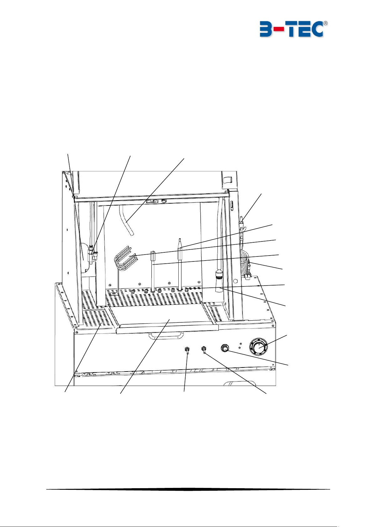
4. Technical Description of the Machine............................................................................................. 7
4.1. Technical Data ......................................................................................................................... 8
4.2. Spare Part Names.................................................................................................................... 9
4.3. Pneumatic Diagram............................................................................................................... 10
4.4. Spare Parts Ordering Numbers and Accessories................................................................... 11
5. Zone and Machine Classification according to ATEX..................................................................... 12
6. Requirements for the Installation Site .......................................................................................... 12
7. Transport and Installation............................................................................................................. 13
7.1. Exhaust Ducting..................................................................................................................... 13
7.2. Compressed Air Connection.................................................................................................. 14
7.3. Grounding / Earthing............................................................................................................. 14
8. Commissioning .............................................................................................................................. 15
8.1. Containers for Cleaning Fluid ................................................................................................ 15
8.2. Positioning of Containers and Hose Allocation..................................................................... 15
9. Working with the Machine............................................................................................................ 16
9.1. Operational Procedure.......................................................................................................... 16
9.2. Adjusting Options.................................................................................................................. 18
10. Care and Maintenance .............................................................................................................. 19
11. Disposal ..................................................................................................................................... 19
12. Troubleshooting ........................................................................................................................ 20
13. Safety Inspection Checklist........................................................................................................ 21
V3.0

Cleaning System ud-800 Page 1
1. Important Information
Thank you for the trust you placed in us by purchasing this B-TEC product. On the machines type plate
you find the exact type designation and serial number to ensure good service and shipment of spare
parts. The cleaners have been designed and manufactured to the highest quality standards for best
operational safety.
Read this document carefully before putting the ma-
chine into operation and keep it for future reference.
On page 21 of this manual, there is a form for documenting the safety inspections to be carried out at
regular intervals. The form has to be filled in by specialist technicians (persons with sufficient
knowledge and experience or manufacturer's technicians) or experts (e.g. engineers or Technical Con-
trol Board experts).
A safety inspection must be carried out before
commissioning and at least once a year.
B-TEC machines are to be used solely in accordance with the intended use. Usage not in accordance
with the intended use as well as unauthorised modifications invalidate the liability of the manufacturer
for any damages resulting from this. Detailed information regarding intended use to as well as liability
and warranty can be read in section 1.3 and 1.4.
The B-TEC machines are only to be used according to the intended used. Im-
proper use of the machine can endanger the health of the operator.
1.1. Explanation of the Symbols
To directly draw attention to important information in this operating manual, the symbols "Caution!"
and "Notice!" are used. Please note that paragraphs with these symbols need particular attention.
Caution!
You will see this symbol whenever attention is drawn to situations in which danger to life
can arise due to or during incorrect or improper operation. Pay special attention to these
symbols and act carefully.
Notice!
You will see this symbol in the operating manual whenever your attention is being drawn
to correct work procedures, economic ways of operating or when the machines may be
damaged by incorrect operation.
1.2. Operating Instruction
The responsible person within the company where the machine is placed has to create operating in-
structions in accordance with the "Occupational Safety and Health Regulations" applicable in the re-
spective country. The operating instructions must be adapted to the cleaning fluid used and country
of application.
1.3. Liability and Warranty
The cleaning machine is state of the art, tested and operationally safe. Liability for the function of the
machine is transferred to the operating company, if the machine is improperly maintained or repaired
by persons who are not authorised by the manufacturer and / or supplier, or if it’s used against the

Cleaning System ud-800 Page 2
intended use and the instructions of the user manual. The operator is obliged to operate the machine
only when in immaculate condition. Themanufacturer is liable for errors or omissions - to the exclusion
of further claims - only within the scope of the statutory warranty obligations. We reserve the right to
make technical changes any time for continuous development and improvement of our products. Such
changes, mistakes and misprints do not constitute a claim for damages. Only original spare parts and
accessories are to be used. The manufacturer and / or supplier is not responsible for damages caused
by ignoring the instructions in this operating manual. Warranty and liability conditions of the manu-
facturers and / or supplier sales and delivery terms are not extended by the above notes.
B-TEC warrants its products to be free from defects in materials and workmanship, for a period of 24
months on a one shift basis. In case of exceptional usage such as multiple-shift operation, the statutory
warranty is shortened to 12 months (two-shift operation) or 8 months (three-shift operation). The
period starts from the date the machine is shipped from the factory. The guarantee expires prema-
turely if the customer or a third party undertakes inappropriate modifications or repairs or if the cus-
tomer, in case of a defect, does not immediately take all appropriate steps to mitigate the damage and
give the supplier the possibility of remedying such defect.
1.4. Intended Use
This spray gun cleaning system may only be used for its intended purpose. It is not
intended for other purposes than the following terms. The manufacturer/supplier is
not liable for any damages resulting from improper use.
The intended use of this machine is to clean spray guns or paint-soiled parts/tools (e.g. stirring rods,
mixing bowls etc.).
The machine can be used with the following cleaning agents (For details see section 3):
Solvents (GHS categories 2 and 3).
Non-combustible, water-based cleaning fluids for water soluble paints.
Cleaning agents containing more than 65% of acetone are not permitted.
This machine is for commercial use only, but not for continuous operation (e.g. serial production).
This machine is classified as equipment group II, equipment category 2G, type of protection Ex h, eligi-
ble for gases of explosion group IIB, equipment protection level Gb and can be used in zone 1.
See also type plate:
II 2G Ex h IIB T6 Gb
Improper use of the machine can endanger the health of the operator and of others and cause damage
to the cleaner itself or to other objects. Any other use of the machine must be agreed and approved
with the manufacturer in advance.
1.5. Requirements to be the Operator
The machine may only be used by competent personnel who, by virtue of their training, knowledge or
experience, ensure proper handling and are aware of the dangers (for example, by reading the oper-
ating manual).

Cleaning System ud-800 Page 3
2. Safety Requirements
2.1. General Safety
The machine is built according to the state of the technology and can be operated safely. However,
this does not mean that the consequences of all operational failures are protected by technical
measures. Dangers can arise from this machine if it is used improperly or incorrectly. However, addi-
tional organisational measures have to be taken into account for certain workflows, such as the re-
moval of residual paint from the gun.
Read and follow the operating instructions for machine as well as the safety instructions be-
fore commissioning.
Always keep the manual available in the immediate vicinity of the machine.
The machine may only be operated by trained personnel. Operators under the age of 18 are
only allowed to operate the machine when under supervision of an expert.
For some users, hazard assessment activity restrictions may result, e.g. for persons with
chronic respiratory problems or allergic diseases as well as for pregnant women or nursing
mothers.
For the correct operation of the machine, the safety and operating instructions are valid in
all cases. These must be read carefully and followed strictly!
The manufacturer recommends to strictly follow the occupational safety provisions, rules and infor-
mation applicable in the respective country for using spray gun and part cleaning systems such as the
following examples: "Accident prevention - Principles and prevention", "Safety and health protection
warnings at the workplace", "Safety rules for air pollution control systems for the workplace", "Safe
use of the machine by following operating instructions", "Safe use of the machine by following oper-
ating instructions", "Avoidance of ignition from electrostatic charges", "Guidelines for facilities for
cleaning parts with solvents", "Use of protective clothing", "Use of eye and face protection", "Use of
protective gloves", " Industrial Safety".
2.2. Operational Safety
Follow the information and warning signs at-
tached to the machine.
The machine may only be operated, if:
othe integrated suction machine (Venturi system with flexible exhaust hose) is con-
nected and the resultant (solvent-) fumes are safely discharged to the outside in the
free air in order to avoid fire, explosion and health hazards. See section 7.1.
ogrounding / earthing is ensured using a grounding cable (potential equalisation)! Con-
nection must be carried out by a specialist. See section 7.3.
In all cases, the local safety and accident prevention rules for the use of the machine must be
followed.
Fire, naked flame and smoking prohibited.

Cleaning System ud-800 Page 4
Open fires and other sources of ignition (e.g. due to grinding or welding, any flying
sparks) are not allowed within a radius of 1 metre around the machine. This applies
also e.g. for lighting and fans as well as the associated electrical components.
Depending on the cleaning application, use the required personal protective and chemical re-
sistant protective equipment. The minimum required protective equipment is eye protection
and gloves. Optionally protective clothing and safety shoes are recommended.
Minimal require-
ment:
Optional:
Ensure that clothing (especially footwear) is conductive.
Do not place the protective equipment on the machine.
If clothing has been wetted with solvent / cleaning fluid, smoking is also prohibited outside the
Ex-zone. Take off the contaminated clothing immediately. There is risk of skin irritation, aller-
gies, etc. Persons wearing contaminated clothing must not be exposed to sources of ignition
(e.g. welding). Risk of fire.
In the event of a fire, immediately stop the compressed air supply and close the door of the
machine.
Compliance with country-specific workplace exposure limits legislation according to safety
data sheets must be documented.
The limit values of the country specific air pollution and adherence thereto must be observed.
If the machine is not used, the door must always be closed for safety reasons.
The operator has to ensure that nobody else is in the working area of the machine.
Use only permitted solvents / cleaning fluids (section 3). These must be free of Halogenated
hydrocarbons (CKW, CFC, TRI, PER, etc.).
If water (e.g. with additives) is used as a cleaning fluid, this must not be discharged into the
sewer system.
Pay attention to the safety data sheet of the cleaning fluid.
Do not eat or drink near the machine. Clean your hands before eating any food or drink after
working. Danger of poisoning!
Avoid inhalation of fumes and contact with the solvent / cleaning fluids. Risk of respiratory
tract irritation!
Do not add any other liquids to the cleaning fluid, such as kerosene, gasoline, chlorinated hy-
drocarbons, acids, alkalis, pickling agent or brake cleaner.
Do not overfill the unit with cleaning fluid, as this may lead to an overflow of the barrel.
Immediately collect spilled solvent(s) with suitable binders and dispose them in accordance
with regulations. The water resources legislation must be complied with.
When changing the cleaning fluid, all applicable regulations (e.g. waste water regulations) must
be observed!
It is prohibited to open the pump casing in the machine. The manufacturer is not lia-
ble for any damage and/or secondary/subsequent damage caused by opening the
pump casing on purpose or negligent opening. If you have any problems with your
pump, please contact your distributor or the manufacturer’s support service.

Cleaning System ud-800 Page 5
2.3. Hazards from Pneumatic Energy
Only specialists with expert knowledge and experience may work on pneumatic machines. When work-
ing on pneumatic systems, these must be disconnected from the air supply and de-pressurised in order
to prevent injury.
2.4. Suggestions for Operating Instructions
Operating instructions are regulations that a company creates for safe working for its employees.
These are binding instructions issued by the company in line with its policy and the law. Employees are
obligated to follow these instructions.
The employer is responsible for creating and publishing workplace related operating procedures e.g.
regarding Occupational Safety and Health Regulations, the Water Resources Legislation and, where
applicable, the Control of Hazardous Substances applicable in the relevant country. These operating
instructions are therefore to be complemented by national regulations on accident prevention and
environmental protection.
Give your employee e.g. the following information:
The hazards involving the handling of contaminated parts and the solvents used, the necessary
protective measures and guidelines, including instructions in case of danger and first aid.
The type and scope of periodic inspection for the safe working condition of the machine.
Environmental Protection.
Safe operation of the pneumatic system.
Clean and safe working environment.
The responsibility for operation must be clearly regulated by the company and must be com-
plied with by all persons designated to operate the machine. Under no circumstances should
unauthorised or untrained persons use the machine.
The operator has to operate the cleaning machine only in perfect condition and has to notify
their supervisor immediately in case of any changes affecting safety and environmental pro-
tection.
Follow all warnings and warning signs.

Cleaning System ud-800 Page 6
3. Approved Cleaning Agents
Only use solvents / cleaning fluids that meet the following specifications:
Highly flammable liquids (category 2, flam. liq. 2):
oGHS/CLP H225, flash point <23°C, boiling point >35°C.
oFormerly according to 67/548/EWG: R11, Hazard symbol „F“.
Flammable liquids (category 3, flam. liq. 3):
oGHS/CLP H226, flash point 23°C - 60°C.
oFormerly according to 67/548/EWG: R10, no Hazard symbol.
Non-combustible, aqueous cleaning agents (neutral or slightly alkaline pH) such as B-TEC H2O
Cleaner for water-soluble paints.
If using flammable cleaning liquids, ensure at least a medium electrical conductivity of the liquid. Usu-
ally solvents are mixtures of liquids with high and low conductivity and therefore are sufficiently con-
ductive. If you have any doubts, ask your supplier.
It’s recommended to use purified water to mix B-TEC H2O-RK cleaner, if tap water is
extremely hard water or contains high quantities of iron.
Ensure that the used cleaning fluid is suitable and does not attack the surface of the
object to be cleaned. Suitability shall be ensured by the operator in preliminary tests.
The manufacturer and / or supplier does not assume any liability for damages caused
by these tests.
Acids are not permitted. Paint strippers or other additives (e.g. brake cleaners etc.)
must not be used in the machine.
Safety data sheets relevant to the products supplied should always be available on the
premises. These will contain the information about the cleaning agents that you are
using.
Never alternate the use of solvents and cleaning fluids (for water-based paints) in the
same machine as this will damage it and void the warranty. Follow the manufacturer’s
instructions at all times. Alternating the two types of cleaning agents can cause gas
build up and explosions!
When changing from solvents to cleaning fluids for water-based paints (or vice-versa)
the paint gun cleaner must be completely cleaned of paint, water and fluid residues.
Recommendation to reduce solvent consumption:
If the machine is connected to a continuously running exhaust system and you’re using
solvent, we recommend the pneumatic exhaust solvent safer to reduce solvent con-
sumption.
See B-TEC catalogue number:
Pneumatic exhaust solvent saver diameter 125 mm art.-no.: 10000348

Cleaning System ud-800 Page 7
4. Technical Description of the Machine
The ud-800 is a cleaning system for automatically cleaning spray paint guns. The automatic cleaning
cycle is activated by a timer. In addition, there is a brush and a clean rinse nozzle in the cleaning cham-
ber for cleaning objects or spray guns manually.
Furthermore the machine has a blow-off gun for drying and blowing out cleaned spray paint guns. The
machine has a strong exhaust suction system that switches on and off automatically as soon as the
machine's door is opened or closed. The machine is operated exclusively by pneumatic parts.
Figure 4-1
- Technical changes and errors reserved. All pictures similar -
Cup holder
Paint-channel nozzle
Blow-off gun
Air-connection
Brush with hose
Timer
Button for clean
rinse
Toggle-switch for
clean rinse nozzle
Toggle-switch for manual
cleaning brush
Door automatic
cleaning chamber
Lid support (fork)
Blow-out opening
Clean rinse nozzle
Compressed air hose for
flushing spray gun
Spray nozzle
Perforated stain-
less steel grill

Cleaning System ud-800 Page 8
4.1. Technical Data
Figure 4-2
- Technical changes and errors reserved. All pictures similar -
1750
600
750
1060
1510
1590
1750
220
355
450
570
470 520
Compressed air connection
Operating pressure:
Compressed air demand:
max. 6 bar
240 l/min
Acoustic emission
Average level of acoustic emission:
78 dB(A)
Exhaust air flow rate
Total at 0.2 m/s:
213 m³/h
Machine dimensions (per side)
Machine outside (Width × Height × Depth):
Washing chamber total (W × H × D):
750 × 1750 × 600 [mm]
570 × 450 × 520 [mm]
Washing chamber autom. cleaning (W × H × D):
470 × 355 × 220 [mm]
Size of the container below the cleaning machine
1 × container for circulating fluid. Container size max. 60 litres.
1 × container for fresh fluid. Container size max. 30 litres.

Cleaning System ud-800 Page 9
4.2. Spare Part Names
A-1
-
Pump for manual cleaning brush
Q
-
Transport rolls for roller bund
A-2
-
Pump for automatic cleaning cycle
R
-
Double ball catch
A-3
-
Pump for clean rinse
S
-
Draining hose
AR
-
Check-valve
T-1
-
Intake strainer
B
-
Toggle switch
T-2
-
Strainer one ear clamp
D
-
Roller valve for activation
U-1
-
Corrugated hose, transparent
E
-
Roller valve for inside door or timer
U-2
-
Corrugated hose, grey
G
-
Button clean rinse
V
-
Brush with hose
H
-
Clean rinse nozzle
W
-
Hose for air flushing
K
-
Timer
X
-
Grounding cable
L
-
Compressed air connection plug
Y-1
-
Blow-off gun with short tube
M
-
Paint channel nozzle
Y-2
-
Brass connection socket
N
-
Cup holder
Y-3
-
Coil hose
O
-
Lid support (fork)
Z
-
Exhaust hose alu 125 mm
P
-
Spray nozzle
- Technical changes and errors reserved. All pictures similar -
Figure 4-3
G
L
V
AR
A-3
A-2
A-1
B
D
R
E
Y-1
H
O
N
M
U-2
U-1
T-2
T-1
W
X
K
S
Z
P
Y-3
Y-2
Q

Cleaning System ud-800 Page 10
Figure 4-4
4.3. Pneumatic Diagram
- Technical changes and errors reserved. All pictures similar -
A-2
C
E
A-1
K-5
A-3
I-3
G
C
C
K-4
K-3
K-1
B
B
H
C
F
C
J
D
I-1
Air connection plug L
K-2
E
Y-1
I-3
I-2
Y-2
Y-3
I-4
I-4
W

Cleaning System ud-800 Page 11
4.4. Spare Parts Ordering Numbers and Accessories
A
-
Main Pump ¼”
10000554
-
Connector for pump ¼”, incl. O-ring (included in art.-no. 10000554)
10000561
AR
-
Check-valve, inner thread, G 1/4" EPDM
10001069
B
-
Toggle-switch
10000589
C
-
Flow adjuster
10000582
D
-
Roller valve for activation
10000620
E
-
Roller valve for inside door or timer
10000579
F
-
Air suction nozzle
10000415
G
-
Button for automatic clean rinse, completely assembled
10000414
H
-
Clean rinse nozzle complete with pipe and connection
10001116
I-1
-
T-plug connector 2 x 8 mm, 1 x 6 mm
10000847
I-2
-
T-plug connector 6 mm
10000845
I-3
-
Y-plug connector 6 mm
10000896
I-4
-
Connector 6mm with check-valve function
10001371
J
-
Cross connector 6 mm
10000893
K
-
Timer complete (Time-limit switch, timer knob and scale)
10000416
K-1
-
Timer –Time limit switch 6 min
10000444
K-2
-
Timer –Fixing plate
10000327
K-3
-
Timer –Switching disk
10000328
K-4
-
Timer –Scale for timer 0 –6 min
10000445
K-5
-
Timer –Timer knob
10000443
L
-
Compressed air connection plug
10000908
M
-
Paint channel nozzle complete with pipe
10000420
N
-
Cup holder complete
10000418
O
-
Lid support (fork)
10000439
P
-
Spray nozzle
10000429
Q
-
Transport rolls unit consist out of 8 rolls
10000462
R
-
Double ball catch
10000467
S
-
Corrugated hose for draining
10000658
T-1
-
Strainer, stainless steel
10000473
T-2
-
Strainer one ear clamp
10000649
U-1
-
Corrugated hose, transparent
10000656
U-2
-
Corrugated hose, grey
10000655
V
-
Brush with hose
10000417
W
-
Corrugated hose for air flushing, black
10000657
X
-
Grounding / earthing cable
10000958
Y-1
-
Blow-off gun with short tube
10000446
Y-2
-
Brass connection socket 1/4" interior 7.2
10000610
Y-3
-
Coil hose 1m with Connectors angle and straight + double nipple
10000645
Z
-
Exhaust hose aluminium 125 mm
10000644
Trigger clamp standard, stainless steel
10000436
Accessories
Pneumatic exhaust solvent saver, ATEX - 125 mm
10000348
H2O-Cleaner-RK, water based paint cleaner concentrate, 10 L
10000633
Plastic container 30,0 L with cap, non-conducting
10000711
Plastic container 30,0 L with cap, conducting
10000691
Plastic container 60,0 L with cap, conducting
10000767
Pressure reducer with manometer 1/8" incl air connector
10000619

Cleaning System ud-800 Page 12
5. Zone and Machine Classification according to ATEX
This machine is classified as equipment group II, equipment category 2G, type of protection Ex h, eligi-
ble for gases of explosion group IIB, equipment protection level Gb and can be used in zone 1.
See also type plate:
II 2G Ex h IIB T6 Gb
In accordance with legal requirements, the ATEX zone definition around the machine and creation of
an explosion protection document comes under the responsibility of the "responsible person of the
company" where the machine is placed as this classification is subject to the cleaning fluid used and
various conditions such as ventilation.
However, at this point the operator should be supported with general advice to comply with this ob-
ligation. Helpful advice can also be found in EN 12921‐1 and ‐3 and EN ISO 80079-36.
If using the machine with flammable cleaning fluids, the following zone designation has to be consid-
ered:
Zone 1
→
The interior of the machine
Zone 2
→
Surroundings within 1.0 m
Mark the different zones with appropriate warning and prohibition signs. Markings on the floor can be
helpful. In the area surrounding the machine, open flames and other ignition sources (e.g. welding or
grinding equipment) are not allowed. In addition, smoking is prohibited. Temporary work causing igni-
tion sources must be approved in writing and appropriate additional safety measures must be applied
(e.g. remove all combustible materials; firefighting equipment must be on hand in the working area.)
6. Requirements for the Installation Site
Horizontal industrial floor with electrical resistance of max. 108Ohm.
Dry and protected from frost.
Very good technical room ventilation with at least 5 air changes per hour (Depending on local
regulations).
Do not install or operate the machine within a radius of 1.5 m from heat sources.
Ensure an ambient temperature of 5 °C –40 °C and do not expose the machine to direct sun-
light, as this carries a risk of overheating.
Follow the relevant legislative and regulatory safety instructions regarding substances hazard-
ous to water applicable in the country where the machine is installed.
Follow the safety regulations according to zone designation.
The machine can be placed against the wall or in a corner. A 1.5 m space should be provided
in front of the machine.
Requirement in German DGUV (German Social Accident Insurance) Information 209-046:
“In rooms with filling, mixing and pumping of flammable liquids you must have at least 5 air
changes per hour. Therefore, a technical room ventilation system is required. The air-outlet
opening must be near the ground. Air-inlet and –outlet must be placed in a way that a com-
plete and even air exchange is achieved”

Cleaning System ud-800 Page 13
7. Transport and Installation
The machine is delivered packed. Unpack the machine outside an explosive atmosphere and bring it
to the installation site. Install the machine as described in the following sections.
7.1. Exhaust Ducting
The exhaust air hose must be integrated in the ex-
haust system at the installation site and must be
routed outdoors properly into the so-called "free air
space". Place the exhaust air hose vertically, a mini-
mum of one metre for optimal function of the ex-
haust system and stretch the hose as far as possible
in order to avoid a reduced cross-section. In this way
optimal exhaust suction will be achieved.
Ensure that fumes are not directed into areas where
people are likely to be. The exhaust air has to be led
away safely. That means according to ATEX and espe-
cially not into flues serving furnaces or fireplaces and
not into the exhaust ducts of spraying and drying cab-
inets. In case the exhaust system conditions at the in-
stallation site require a longer exhaust air hose or the
instructions in how to route the exhaust air system
cannot be complied with, please contact an ATEX-
ventilation system specialist to ensure safe opera-
tion. The power of the integrated air suction nozzle is
limited to max. ca. 4 metres of ducting, depending on
the route of ducts (corners, radii, height). An explo-
sion-proof exhaust fan is required for longer ducting.
It’s recommended not to connect the machine di-
rectly to a rigid pipe. Use at least 30-40 cm of the flex-
ible B-TEC exhaust hose to ensure that the machine
can be relocated or repaired conveniently if neces-
sary.
Diameter of exhaust hose: Ø125 mm
Figure 7-1
The exhaust air flow rate can be adjusted at the flow adjuster as needed depending on the length
of the duct.
Caution! Only use original B-TEC exhaust air
hoses! Risk of fire! Do not use plastic hoses!
- Technical changes and errors reserved. All pictures similar -
min. 1000mm
ca. 30-40cm
Flexible B-TEC
exhaust hose
Rigid piping of
customer

Cleaning System ud-800 Page 14
7.2. Compressed Air Connection
A compressed air supply is needed for the machine.
Operating pressure max.: 600 kPa (6 bar , 87 psi)
Operating pressure min.: 500 kPa (5 bar , 73 psi)
Figure 7-2
A pressure regulating valve (Item no.: 10000619)
has to be fitted if the compressed air connection
exceeds the required operating pressure. Use only
dry and oil-free air!
7.3. Grounding / Earthing
The machine has a grounding / earthing connection
and may not be operated without being grounded!
The machine has a grounding / earthing cable, which needs to be grounded / earthed safely by a com-
petent person (e.g. electrician). Customer-provided containers have to be grounded separately!
After proper installation and mounting of the exhaust hose, connection to the compressed air supply
and grounding, the machine can be commissioned.
- Technical changes and errors reserved. All pictures similar -
Air connection

Cleaning System ud-800 Page 15
8. Commissioning
Commissioning may be done only after reading and following the operating manual
carefully! Commissioning performed without following the operating manual and com-
plying with all applicable regulations can lead to damage to persons, property, or the
environment. Wear personal protective clothing. See section 2.2 ‐Operational Safety).
After proper installation (Section 5 & 6) and mounting of the exhaust hose (Section 7.1), connection to
the compressed air supply (Section 7.2) and grounding (7.3), the machine can be commissioned.
8.1. Containers for Cleaning Fluid
1 × 60 litre container filled with 30 litres (recirculating fluid) and 1 × 30 litre container filled with 30
litres (fresh fluid). See Figure 8-1. When refilling the fresh fluid, ensure that the container for circulating
liquid has a remaining capacity of 30 litres to prevent overflowing of liquid. It is recommended to also
renew the circulating liquid when refilling the clean rinse liquid.
8.2. Positioning of Containers and Hose Allocation
1. Remove the front cover and place the containers as shown in Figure 8-1.
2. Moisten the draining and intake hoses incl. intake strainer with a wet cloth and insert the moist
hoses as follows: Insert the black draining hose (Ø 28 mm) and grey intake hoses into the 60
litre container, which is provided for recirculating cleaning fluid. Insert the transparent hose
into the 30 litre container for fresh cleaning fluid.
3. Reinsert the front cover.
The machine is now ready for operation.
Figure 8-1
Recirculating fluid
(Black and grey hose)
Fresh fluid
(Transparent hose)

Cleaning System ud-800 Page 16
9. Working with the Machine
9.1. Operational Procedure
Working with the manual cleaning area of the machine (see also Figure 4-1 & Figure 4-3)
Open the main door. The exhaust suction system starts working automatically.
Activate the pump for the brush with the toggle-switch labelled "Brush". The recircu-
lating cleaning fluid from the 60 litre container flows through the brush.
The clean rinse nozzle can be activated by the toggle-switch "Clean rinse". Fresh clean-
ing fluid flows from the 30 litre container.
The output can be adjusted with a flow adjuster (See colour coding on this page or
section 9.2).
Brush
Clean rinse
Colour coding of the hoses for the manual cleaning area:
Green: Brush
Black: Clean rinse nozzle
With the blow-off gun you can dry objects or spray guns. You can disconnect the blow-off gun and
plug in the cleaned spray gun to blow it out into the blow-off opening.
When the manual cleaning area is no longer required, close the main door. The exhaust suction stops
automatically.
Do not allow the doors to slam shut! All doors must be handled
carefully and with caution by the user!
Working with the automatic cleaning area of the machine (see also Figure 4-1 & Figure 4-3)
Open the main door. The exhaust suction system starts working automatically. Open the door of the
automatic cleaning chamber and place the gun as follows (Figure 9-1):
1. Remove the lid of the cup and place it into the lid support fork. Ensure that the paint-soiled
inner surface faces downwards towards the interior of the cleaner.
2. Paint spray gun without strainer: Place the gun upside down on the paint channel nozzle with-
out pulling the trigger. The cup stays screwed.
Paint spray gun with strainer: Unscrew the cup and place it upside down on the cup holder.
Remove the strainer from the spray gun and place it on one of the tines of the lid support fork.
Then place the spray gun upside down on the paint channel nozzle without pulling the trigger.
3. Now the gun is inverted. Pull back the trigger and dip it with the trigger clamp. Keep trigger
clamp always in cleaning chamber.
This ensures that the paint channel is opened for cleaning and remaining
paint can drain from cup connection socket.

Cleaning System ud-800 Page 17
Figure 9-1
4. Connect black hose for air flushing to the spray gun. Ensure that the set screw on the gun is in
the "opened" position to allow air flow.
This ensures that the air channels of the spray gun are pressurised during the
cleaning process and therefore cleaning fluid and paints cannot enter the air
channels or the air cap.
The spray gun is now positioned properly.
5. Close door of automatic cleaning chamber and the main door.
Do not allow the doors to slam shut! All doors must be handled
carefully and with caution by the user!
6. Set timer to 1-3 minutes. The main cleaning cycle is activated. Cleaning fluid is
drawn from the 60 litre container and circulates. The timer can be reset to zero
by hand to stop the cleaning cycle. When the set time is over, open the door
slowly and check the cleaning result.
Main clean-
ing cycle
Do not open the door of automatic cleaning chamber while auto-
matic cleaning cycle is running! If necessary, turn the timer to "0".
Main door
Trigger clamp
Lid
Cup
Door automatic
cleaning cham-
ber
Table of contents