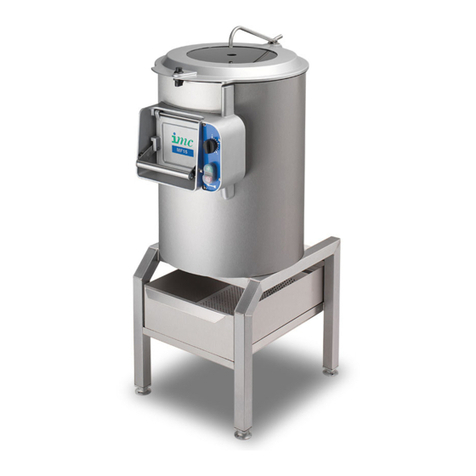
IMC 1 Series User manual

1 | P a g e
SMP-RANGE
SMP25
SMP25 –SERIES 1
INSTALLATION AND OPERATING MANUAL
PLEASE LEAVE WITH OPERATOR
A34/033 R5 ECN 8671 October 2017

2 | P a g e
SMP-RANGE
EC DECLARATION OF CONFORMITY
(Guarantee of Production Quality)
We, Imperial Machine Company Limited of:
Unit 1, Abbey Road, Wrexham Industrial Estate, Wrexham, LL13 9RF
Declare under our sole responsibility that the machine
SMP25 –SERIES 1
As described in the attached technical documentation is in conformity with the Machine Safety
Directive 98/37/EC and is manufactured under quality system BS EN ISO 9001. It is also in
conformity with the protection requirements of the Electro Magnetic Compatibility Directive
2004/108/EEC and is manufactured in accordance with harmonised standards EN 61000-6-1
Immunity and EN 61000-6-3 Emissions (plus product specific standards).
It also satisfies the essential requirements of the Low Voltage Directive 2006/95/EC and is
manufactured in accordance with harmonised standard EN 60204-1 Safety of Machinery
(Electrical Equipment).
Approved by E Plumb, Engineering Manager
Signed at Wrexham, Date October 2017

3 | P a g e
SMP-RANGE
CONTENTS
GUARANTEE ....................................................................................................................4
DELIVERY .........................................................................................................................4
SAMPLE RATING LABEL....................................................................................................4
INTRODUCTION ...............................................................................................................5
YOUR PEELER...................................................................................................................5
CONTROLS .......................................................................................................................6
INSTALLATION .................................................................................................................7
WATER SUPPLY................................................................................................................7
WASTE OUTLET................................................................................................................7
ELECTRICITY SUPPLY CONNECTION .................................................................................8
COMMISSIONING ............................................................................................................9
OPERATION .....................................................................................................................9
SAFETY...........................................................................................................................10
CLEANING......................................................................................................................10
DO’S AND DON’TS .........................................................................................................11
MATERIAL CONTENT......................................................................................................11
MAINTENANCE ..............................................................................................................11
WIRING DIAGRAM 3PH UNITS.......................................................................................12
PARTS ILLUSTRATION ....................................................................................................13
SPARE PARTS LIST..........................................................................................................14
3PH ELECTRICAL CHASSIS & CONTROL BOX...................................................................15
ELECTRICAL SPARE PARTS LIST ......................................................................................16
ORDERING SPARE PARTS...............................................................................................16

4 | P a g e
SMP-RANGE
GUARANTEE
This equipment is guaranteed by IMC for 2 Years from the date of purchase from IMC or from one of
its stockists, dealers or distributors.
The guarantee is limited to the replacement of faulty parts or products and excludes any consequential
loss or expense incurred by purchasers. Defects which arise from faulty installation, inadequate
maintenance, incorrect use, connection to the wrong electricity supply or fair wear and tear are not
covered by the guarantee.
PLEASE OBSERVE THESE INSTRUCTIONS CAREFULLY
This guarantee applies in this form to installations within the UK only.
DELIVERY
The machine is packaged in a carton. Please check the contents against the list below.
Peeler Unit 1
Stand & Filter Basket (integral to the peeler) 1
Peeling plate 1
Inlet hose kit (Optional) 1
Instruction Booklet 1
If any accessories have been ordered they will be supplied in separate packages.
Please notify the carrier and the supplier within three days of receipt if anything is missing or damaged.
Check that the correct machine has been supplied and that the voltage, marked on the rating plate on
the motor, is suitable for the supply and control voltage available. The rating plate is located at the back
of the cylinder near the supply cable inlet.
SAMPLE RATING LABEL

5 | P a g e
SMP-RANGE
INTRODUCTION
This machine is intended for peeling potatoes. Its use may be extended to other root vegetables. It is
not recommended to use this machine for peeling onions.
YOUR PEELER

6 | P a g e
SMP-RANGE
CONTROLS
The peeler has an integral control box on the machine.

7 | P a g e
SMP-RANGE
INSTALLATION
The SMP Peeler is supplied with a stand and is designed to be either free standing or screwed to the
floor (screwing to the floor is recommended). The control box is integral to the machine.
Place the machine in its desired location; level the machine by using a spirit level & adjusting the
levelling feet to suit. If required, mark through the holes in the feet the location of the fixing holes.
Remove the machine and prepare the floor for rawlplugs or other suitable floor fixings. Replace the
unit into working position and screw through the holes in the feet into the rawlplugs or other suitable
fixings. Tighten up the screws.
WATER SUPPLY
Connect the water supply pipe (IMC Inlet Hose Kit Part No. S58/062, or 12mm (1/2”) bore hose) to the
water inlet pipe located on the top of the lid and secure using hose clips. Fit the other end of the supply
pipe to a cold water supply that incorporates a tap or shut off valve that can be used to regulate the
water flow to approximately 3 –4 litres per minute, experience will dictate how much water is required.
Too much and it will splash out of the opening in the lid, too little and waste will collect underneath the
peeler plate. During operation however, there may be minor splashing on the surface of the lid; if this
becomes severe, reduce water flow as required. The maximum water pressure for the supply is 10 bar.
Ensure that an old hose is not used.
PLEASE NOTE: These machines are fitted with a WRAS Approved Type A air-break to prevent back
syphonage into the mains supply. Some local authorities may nevertheless require connection is made
to a storage cistern rather than direct to the mains supply.
This applies to UK installations only. Overseas customers should install the machine in accordance with
local regulations.
If in doubt, check with your local authority
WASTE OUTLET
The peeler has two fixed internal waste outlet locations which both drain into the filter basket located
in the stand, if it is required to remove the waste outlet/s for any reason, it is ESSENTIAL to remove &
discard the gaskets & replace with new ones, (Part No. A11/026).
The waste is discharged from the peeler, through the filter basket and into the drain tray of the stand,
which has a 38mm waste pipe connection. This pipe may either discharge into a gully beneath the
machine or it may be connected via a shallow seal waste trap and fixed pipework into the waste water
system of the building.

8 | P a g e
SMP-RANGE
ELECTRICITY SUPPLY CONNECTION
Before connecting, examine the rating plate attached to the machine to ensure that the characteristics
shown are correct for the supply available. Any changes to the supply or new mains runs should be
carried out by a qualified electrician and in accordance with the IEE Codes of Practice.
These three phase machines should be connected to a 15A isolator providing at least 3mm separation
in all poles. The isolator should be fused at 10A.
The supply to the machine must also be protected by a 30mA RCD.
The mains lead fitted to the machine is the minimum required for individual connection to the mains
supply. Site conditions may vary with additional length of cable run, encapsulation in trunking, etc.
being required. Should this apply, a qualified electrician must alter the lead in accordance with the IEE
Codes of Practice.
WARNING: This machine must be earthed
The wires in the mains lead for three phase supply are coloured:
Green and Yellow Earth
Brown Phase 1
Black
Phase 2
Blue Phase 3
These 3 phase machines do not have a neutral wire. If the supply has a neutral wire isolate it and only
wire the unit to the 3 phases and earth. An equipotential earthing point is located on the back of the
cylinder near the cable outlet if equipotential bonding is required.
Should the mains lead become damaged, it must be replaced by an IMC service agent or a qualified
electrician in order to avoid a hazard.
Should the Control Box baseplate be removed for any reason, the gasket MUST be discarded & replaced
with a new one, (Part No. A11/271).

9 | P a g e
SMP-RANGE
COMMISSIONING
After making the electrical connection, switch on the machine, and check that the direction of rotation
of the peeling plate is CLOCKWISE when viewed from above.
To change the direction of rotation of three phase units, switch off the machine, isolate the supply and
interchange any two of the phase wires. Only a qualified electrician should carry out this change.
OPERATION
1Fit the peeling plate, ensuring that it is properly located on the drive shaft.
2Measure out the potatoes into a container that holds a known measured weight of 25kg of
potatoes. Check the potatoes for stones prior to loading; these could seriously damage the
abrasive. Should stones be present, there will be a discernible noise difference upon operating
the peeler, which will indicate the presence of stones. Switch off IMMEDIATELY and remove the
stones to prevent any damage.
3Load the potatoes into the peeler and close the lid, ensuring the lid handle is securely latched.
The top of the liner can also be used as a maximum loading line.
4Ensure that the chute discharge door is closed and the handle latched.
5Turn on the water supply.
6Set the run time required on the control box - two minutes is normally more than adequate, and
depress the green start button.
7The machine should now be operating. The progress of the peeling process can be viewed
through the window in the lid.
8The peeler can be stopped at any time by pressing the Stop button. It will also stop on
completion of a timed cycle or on the opening of the lid.
9Should the lid be opened, the peeler will stop operating but the timer will continue to count
down. On closing the lid, the start button can again be depressed and the machine will start up
and continue running again (as long as the timer has not ended its cycle).
10 After peeling, turn off the water supply, open the chute door and while keeping the door open,
depress the Start button to evacuate the potatoes (into a suitable receptacle), release the start
button when the peeler is empty.
11 Keep the peeled potatoes under water until required for cooking.

10 | P a g e
SMP-RANGE
SAFETY
The SMP peeler is controlled so that if the electricity supply is interrupted the machine will not restart
automatically.
ON NO ACCOUNT put a hand or implement into the machine, or wedge the door open while
discharging.
ON NO ACCOUNT overfill the machine, as this could invalidate the warranty.
IT IS ADVISABLE for the first use to peel approximately 10 kilograms of potatoes and run the peeler for
approximately 6 –8 minutes. Discard all of the potatoes from this peel and rinse out the machine. This
will remove any loose grit from the peeling plates.
CLEANING
It is essential to clean the machine at least once a day, preferably at the end of each period of operation.
1Switch off at the socket or isolator.
2Remove the lid.
3Lift out the peeling plate.
4Clean the peeling plate in a sink, pot wash or by hosing with a spray.
5Rinse the inside of the peeling chamber and base with warm water, using a mild detergent if
necessary to remove starch build up. Ensure that the door is closed whilst using a spray or similar
inside the peeler.
6Wipe the exterior of the machine with a damp cloth, again using a mild detergent if required.
7Open the chute door and wipe all surfaces with a damp cloth, again using a mild detergent if
required.
NOTE
DO NOT USE CLEANING MATERIALS CONTAINING ABRASIVES OR BLEACHES.
DO NOT STEAM CLEAN.
DO NOT CLEAN WITH A WATER JET.

11 | P a g e
SMP-RANGE
DO’S AND DON’TS
Do Install on a level service.
Do Ensure power supply isolator or socket is accessible with the peeler installed.
Do Clean the machine after each period of use.
Don’tSit or stand on top of the peeler.
Don’tPlace hands inside unit while discharging or peeling.
Don’tUse the unit outside.
MATERIAL CONTENT
The SMP peeler contains the following materials:
Metals Stainless steel, mild steel (inc plated), aluminium, brass and copper.
Plastics and rubber Polycarbonate, nylon, neoprene rubber and EPDM
Other Aluminium oxide, electrical components.
MAINTENANCE
Other than regular cleaning, the SMP-Range of peelers require no maintenance by the end user. It is
recommended that the unit is serviced by an IMC approved engineer at least once a year.
WARNING. Only suitably qualified personnel should service this equipment after becoming
familiar with all safety notices, installation, operation and maintenance procedures related to
the machine.

12 | P a g e
SMP-RANGE
WIRING DIAGRAM 3PH UNITS

13 | P a g e
SMP-RANGE
PARTS ILLUSTRATION
9
8
76
4
5
323
24
2
1
16
25 & 26
12 & 13
15
14
20
18
22
21
19
17
11
10

14 | P a g e
SMP-RANGE
SPARE PARTS LIST
SMP25 SPARE PARTS
ITEM
PART NUMBER DESCRIPTION
1 S59/226 CATCH TRAY
2 S59/225 STAND ASSEMBLY
3 G40/216 MOTOR GEARBOX 0.75kW 3PH
4 S58/549 BEARING HOUSING ASSEMBLY
5 A02/070 O-RING
6 L21/048 ECCENTRIC
7 M79 DOOR ROLLER
8 S59/253 HANDLE ASSY
9 A13/078 M1 NEOPRENE SPONGE SEAL
10 S59/104 LIMIT SWITCH ASSY
11 E59/085 LID LATCH
12 A13/059 M2 SEALING STRIP MODIFIED
13 A13/060 M2 FILLER STRIP MODIFIED
14 M59/005 LID DISC
15 E59/089 WATER SUPPLY PIPE
16 L59/015 SPACER-LID LATCH
17 K08/192 LID SPONGE SEAL
18 L21/047 HANDLE NUT
19 E59/315 Z LINER
20 S59/240 PEELER PLATE ASSEMBLY
21 D28/029 LID SPINDLE STAR WASHER
22 A11/026 WASTE OUT GASKETS
23 G60/389 MAINS CABLE
24 A10/481 ADJUSTABLE FOOT INSERT
25 J04/217 SHOWER WASTE OUTLET
26 J04/242 WASHER. FOAM
27 S58/062 INLET HOSE KIT
28 K09/088 ADHESIVE CYANOACRYLATE
When ordering spare parts or accessories always quote the SERIES AND SERIAL NUMBER of the
machine, found on the rating label.

15 | P a g e
SMP-RANGE
3PH ELECTRICAL CHASSIS & CONTROL BOX
33a
33b 34a
34b & c

16 | P a g e
SMP-RANGE
ELECTRICAL SPARE PARTS LIST
SMP25 SPARE PARTS
ITEM
PART NUMBER DESCRIPTION
33a G30/343 24V AC MINI CONTACTOR
33b G30/299 OVERLOAD RELAY 1 7- 2.3 AMPS
34a G60/334 TRANSFORMER TERMINATED 6VA 400/24V
34b G35/004 FUSE 0.5A SEMI DELAY
34c G35/012 FUSE HOLDER
35 G45/066 TIMER KNOB
36 G45/110 SWITCH RUBBER BOOT
37 G45/109 ON / OFF SWITCH
38 G34A TIMER
39 A11/219 TIMER GASKET
40 A11/271 ELECTRICAL BOX GASKET
41 G45/111 BUTTON CONTACTORS
ORDERING SPARE PARTS
In the event that spare parts or accessories need to be ordered, please always quote the SERIES AND
SERIAL NUMBER of the machine. This is to be found on the rating plate located near the supply cable.
For installations outside the UK, please contact your supplier.
For information on IMC spares and service support (if applicable), please call IMC on +44 (0)1978
661155. Alternatively, contact us via email or fax:
IMC Spares Desk Fax: +44 (0)1978 667759
E-mail: spares@imco.co.uk
IMC Service Desk Fax: +44 (0)1978 667766
E-mail: service@imco.co.uk
Imperial Machine Company Limited
Unit 1, Abbey Road
Wrexham Industrial Estate
Wrexham
LL13 9RF
E-mail: in[email protected]
Website: www.imco.co.uk
This manual suits for next models
1
Table of contents
Other IMC Commercial Food Equipment manuals
Popular Commercial Food Equipment manuals by other brands

Diamond
Diamond AL1TB/H2-R2 Installation, Operating and Maintenance Instruction

Salva
Salva IVERPAN FC-18 User instructions

Allure
Allure Melanger JR6t Operator's manual

saro
saro FKT 935 operating instructions

Hussmann
Hussmann Rear Roll-in Dairy Installation & operation manual

Cornelius
Cornelius IDC PRO 255 Service manual

Moduline
Moduline HSH E Series Service manual

MINERVA OMEGA
MINERVA OMEGA DERBY 270 operating instructions

Diamond
Diamond OPTIMA 700 Installation, use and maintenance instructions

Diamond
Diamond G9/PLCA4 operating instructions

Cuppone
Cuppone BERNINI BRN 280 Installation

Arneg
Arneg Atlanta Direction for Installation and Use
