IMC VC7 Series 22 Programming manual

PublicationNoST1001F February2001
Imperial Machine Company Limited
Harvey Road, Croxley Green, Herts WD3 3AX, England
Telephone: 01923 718000: International + 44 1923 718000
Fax: 01923 777273: International + 44 1923 777273
Telephone: Service 01923 718017 Spares 01923 718018 Fax: 01923 896256
INSTRUCTIONS FORINSTRUCTIONS FOR
INSTRUCTIONS FORINSTRUCTIONS FOR
INSTRUCTIONS FOR
INSTINST
INSTINST
INSTALLAALLA
ALLAALLA
ALLATION OPERATION OPERA
TION OPERATION OPERA
TION OPERATION AND MAINTENANCETION AND MAINTENANCE
TION AND MAINTENANCETION AND MAINTENANCE
TION AND MAINTENANCE
VC7 SerVC7 Ser
VC7 SerVC7 Ser
VC7 Series 22,ies 22,
ies 22,ies 22,
ies 22, VC14 SerVC14 Ser
VC14 SerVC14 Ser
VC14 Series 25ies 25
ies 25ies 25
ies 25
V RANGE POV RANGE PO
V RANGE POV RANGE PO
V RANGE POTT
TT
TAA
AA
ATT
TT
TO PEELING MAO PEELING MA
O PEELING MAO PEELING MA
O PEELING MACHINESCHINES
CHINESCHINES
CHINES
Cl/SfB (73.4) X

11
11
1
V RANGE POTATO PEELING MACHINES
IndexIndex
IndexIndex
Index PagePage
PagePage
Page
Index .......................................................................................................................... 1
On Delivery ................................................................................................................ 2
Guarantee .................................................................................................................. 2
Installation .................................................................................................................. 2
Electricity Supply Connection..................................................................................... 3
Water Supply.............................................................................................................. 4
Waste Discharge........................................................................................................ 5
Operation and Maintenance ....................................................................................... 6
Maintenance and Spare Parts.................................................................................... 7
Wiring Diagrams 1ph and 3ph models ....................................................................... 8
Parts Illustration ......................................................................................................... 9
Parts List.................................................................................................................. 10

22
22
2
V RANGE POTATO PEELING MACHINES
INTRODUCTIONINTRODUCTION
INTRODUCTIONINTRODUCTION
INTRODUCTION
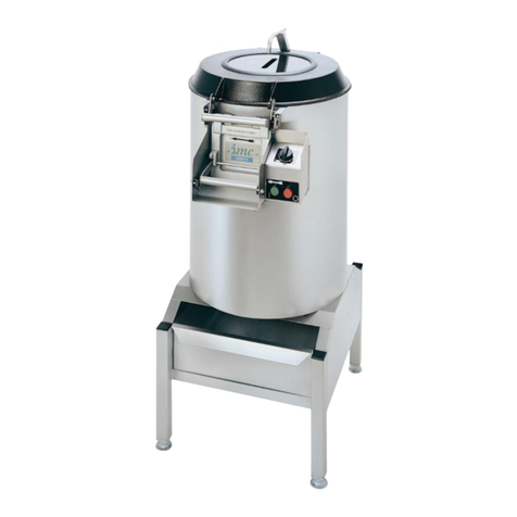
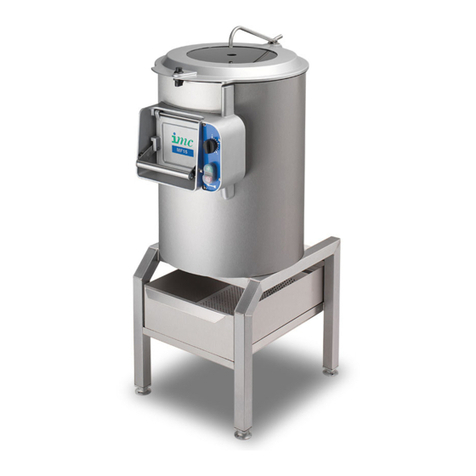
This machine is intended for washing and/or peeling potatoes. Its use may be extended to
certain other root vegetables such as carrots or turnips.
VC7 and VC14 are 3 phase machines without timers. At the date of issue of this manual,
single phase machines are fitted as standard with timers (previously this was an option) and
designated VC7T and VC14T.
ON DELIVERYON DELIVERY
ON DELIVERYON DELIVERY
ON DELIVERY
Bench mounted models VC7 and VC14 may be delivered packed in a carton or unpacked
according to the method of transport. Pedestal models may be delivered unpacked as a
complete unit, or packaged in two cartons. One carton will contain the machine, the other the
telescopic pedestal assembly. Please check the contents and notify both the Carrier and the
Supplier within three days if anything is missing or damaged.
GUARANTEEGUARANTEE
GUARANTEEGUARANTEE
GUARANTEE
This machine is guaranteed by IMC for twelve months from the date of its purchase from IMC
or from one of its stockists, dealers or distributors. The guarantee is limited to the replacement
of parts or products and excludes any consequential loss or expense incurred by purchasers.
Defects which arise from faulty installation, inadequate maintenance, incorrect use, connection
to the wrong electricity supply or fair wear and tear are not covered by the guarantee.
Please observe these instructions carefully.Please observe these instructions carefully.
Please observe these instructions carefully.Please observe these instructions carefully.
Please observe these instructions carefully.
This guarantee applies in this form to installations within the United Kingdom only.
INSTALLATIONINSTALLATION
INSTALLATIONINSTALLATION
INSTALLATION
Bench Models - VC7 and VC14Bench Models - VC7 and VC14
Bench Models - VC7 and VC14Bench Models - VC7 and VC14
Bench Models - VC7 and VC14
These will normally be installed on a work top of some sort or on a draining board. Peeled
potato discharge is commonly into a sink and the sludge discharge can be piped away
separately, possibly using a waste ejector fitting. Alternatively, with lightly used machines the
waste can be directed via an outlet elbow into a sink skip acting as a strainer in the sink.
1 To fasten down the base unit, take off the motor cover. With the cover off, the two
fastening down holes will be visible just forward of the electric motor.
2 Place the base assembly in the required position and mark down through these holes.
3 Remove the base and drill holes through the work top in the marked position.
4 Replace and bolt down using long bolts and nuts (M8 x 95mm are suitable sizes for work
tops of 25mm thickness).
When fixing to a wheeled trolley these same holes are utilised, but the bolts are supplied with
the trolley outfit.
Then proceed with Supply Connection Instructions.

33
33
3
V RANGE POTATO PEELING MACHINES
Pedestal ModelsPedestal Models
Pedestal ModelsPedestal Models
Pedestal Models
These machines must be fastened to the floor.
1 Loosely assemble the machine unit to the pedestal by placing the oval shaped register
around the bottom of the machine unit into the top of the pedestal assembly.
2 Place the whole unit into position and mark around its outside on the floor (note any
height adjustment to be made to pedestal).
3 Put the pedestal back in place on the floor in the mark previously made.
4 Down inside the pedestal the fixing holes will be visible. Mark these through onto the
floor, and fit rawlbolts or other suitable floor fixings.
5 Fasten the pedestal to the floor with these fixings and tighten up. Select height of
pedestal required and secure. Height adjustment to the discharge chute from the floor is
available as follows:
Min 2nd 3rd 4th Max
VC7 725 790 840 890 940mm
VC14 745 810 860 910 960mm
6 Use the rubber plugs to close off the unused holes.
7 Finally, replace the machine unit into the pedestal and fit the three screws tightly.
Proceed with Supply Connection Instructions.
SUPPLY CONNECTION INSTRUCTIONSSUPPLY CONNECTION INSTRUCTIONS
SUPPLY CONNECTION INSTRUCTIONSSUPPLY CONNECTION INSTRUCTIONS
SUPPLY CONNECTION INSTRUCTIONS
ELECTRICITY SUPPLY CONNECTIONELECTRICITY SUPPLY CONNECTION
ELECTRICITY SUPPLY CONNECTIONELECTRICITY SUPPLY CONNECTION
ELECTRICITY SUPPLY CONNECTION
Examine the rating plate attached to the machine to ensure that the characteristics shown are
correct for the supply available.
The control switch should be as near to the machine as the length of cable will allow. If this is
not possible, provided the extra length is not considerable, the cable can be replaced with a
longer piece of the same specification. Unless a jointing box is used DO NOTDO NOT
DO NOTDO NOT
DO NOT splice cable
together but replace with a complete new length back to the terminal box.
The control should be a motor starter but a 13 amp fused or 15 amp round pin switch socket
will serve. These must be 3 pin and EARTHED and on no account must a 5 amp lighting point
be used. Fuse with a 13 amp fuse to BS1363. Three phase machines should be connected to
a 15 amp three pole isolator fused at 5 amps.
When using a motor starter, follow the instructions supplied with it.
New mains supply run to the machine should always be undertaken by a reputable and
competent electrician. The IEE Codes of Practice must be observed.
WW
WW
WARNINGARNING
ARNINGARNING
ARNING: T: T
: T: T
: THISHIS
HISHIS
HIS
APPLIANCEAPPLIANCE
APPLIANCEAPPLIANCE
APPLIANCE
MUSTMUST
MUSTMUST
MUST
BEBE
BEBE
BE
EARTHEDEARTHED
EARTHEDEARTHED
EARTHED

44
44
4
V RANGE POTATO PEELING MACHINES
IMPORTANT - 1 PHASEIMPORTANT - 1 PHASE
IMPORTANT - 1 PHASEIMPORTANT - 1 PHASE
IMPORTANT - 1 PHASE
The wires in the mains lead for single phase machines are coloured in accordance with the
following code:
Green and Yellow EARTH
Brown LIVE
Blue NEUTRAL
As the colours of the flexible cord of this appliance may not correspond with the coloured
marking identifying the terminals in your plug, proceed as follows:
The core which is coloured green and yellow must be connected to the terminal in the plug
which is marked with the letter E or by the earth symbol or coloured green or green and
yellow.
The core which is coloured brown must be connected to the terminal which is marked with the
letter L. The core which is coloured blue must be connected to the terminal which is marked
with the letter N.
IMPORTANT - 3 PHASEIMPORTANT - 3 PHASE
IMPORTANT - 3 PHASEIMPORTANT - 3 PHASE
IMPORTANT - 3 PHASE
The wires in the mains lead for three phase machines are coloured in accordance with the
following code:
Green and Yellow EARTH
or Black/Brown/Blue Phase Wires
After connection, switch on and observe the direction of rotation of the abrasive bottom plate.
This should be clockwise when viewed from above. If not, switch off, and interchange any two
of the phase lead connections.
WATER SUPPLY CONNECTIONWATER SUPPLY CONNECTION
WATER SUPPLY CONNECTIONWATER SUPPLY CONNECTION
WATER SUPPLY CONNECTION
Connections should only be made from a storage tank supply and not directly from the mains.
1/2" bore canvas reinforced hose with hose clips at the ends should be used for the final
connection. Allow sufficient length for the top of the machine to be removed and placed aside
when cleaning without straining or disconnecting the hose. Do not use rigid piping as this will
make internal cleaning difficult unless the machine is dismantled first.
If the supply is taken from a sink tap a Royles Union connection will suffice. Permanent
installations should, however, have a wall mounted control cock fitted with a 1/2" BSP
threaded outlet and hose union.
WASTE OUTLET CONNECTIONWASTE OUTLET CONNECTION
WASTE OUTLET CONNECTIONWASTE OUTLET CONNECTION
WASTE OUTLET CONNECTION
All machines are supplied with 2" BSP threaded outlets: DO NOT REDUCE THIS DIAMETERDO NOT REDUCE THIS DIAMETER
DO NOT REDUCE THIS DIAMETERDO NOT REDUCE THIS DIAMETER
DO NOT REDUCE THIS DIAMETER.
The length of run between the machine and the main junction must be kept to a minimum and
the pipe must have a fall of at least 1:15. Changes of direction should be made by bends
rather than elbows and cleaning eyes should be fitted where possible, in accordance with
standard plumbing practice.
This manual suits for next models
1
Table of contents
Other IMC Commercial Food Equipment manuals
Popular Commercial Food Equipment manuals by other brands

Diamond
Diamond AL1TB/H2-R2 Installation, Operating and Maintenance Instruction

Salva
Salva IVERPAN FC-18 User instructions

Allure
Allure Melanger JR6t Operator's manual

saro
saro FKT 935 operating instructions

Hussmann
Hussmann Rear Roll-in Dairy Installation & operation manual

Cornelius
Cornelius IDC PRO 255 Service manual

Moduline
Moduline HSH E Series Service manual

MINERVA OMEGA
MINERVA OMEGA DERBY 270 operating instructions

Diamond
Diamond OPTIMA 700 Installation, use and maintenance instructions

Diamond
Diamond G9/PLCA4 operating instructions

Cuppone
Cuppone BERNINI BRN 280 Installation

Arneg
Arneg Atlanta Direction for Installation and Use
