7 | P a g e
SP-RANGE
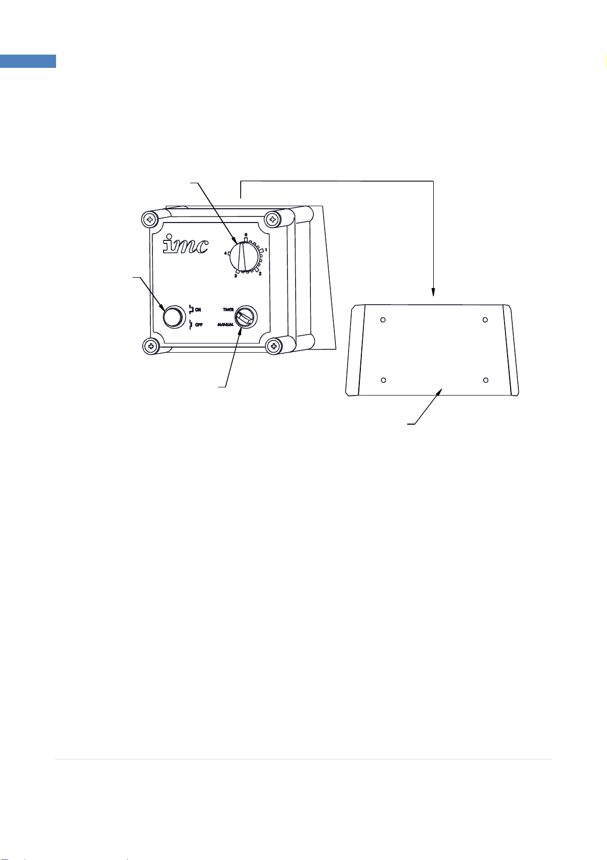
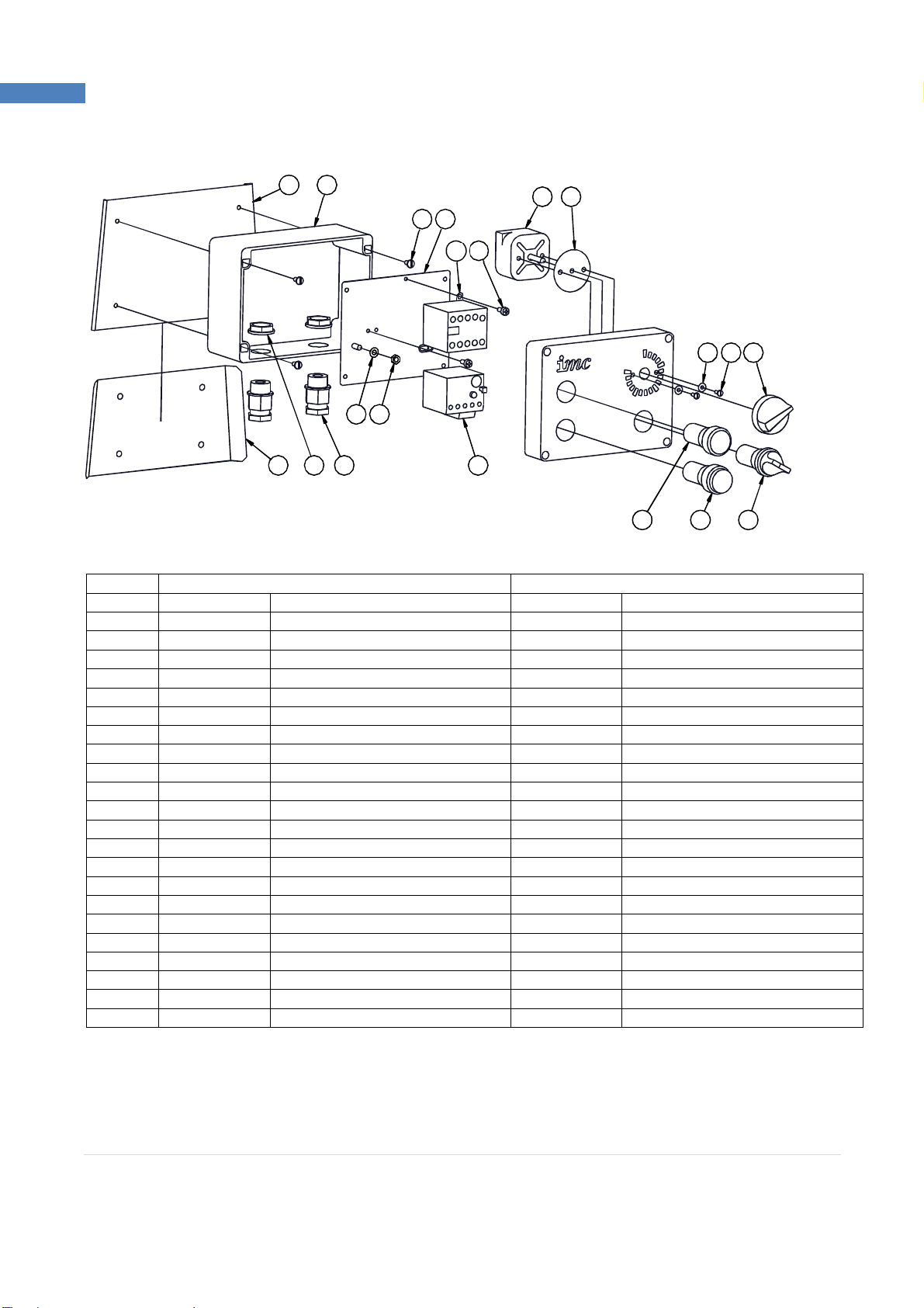
Place the control box bracket in the desired location and mark through the four screw holes. Remove
the bracket and prepare the wall for rawl plugs or other suitable wall fixings. Secure the bracket in
place with four screws. Slide the control box onto its wall bracket.
WATER SUPPLY
Connect the water supply pipe to the water inlet located on the top of the lid, and secure using the
supplied hose clips. Fit the other end of the supply pipe to a cold water supply that incorporates a tap
or shut off valve that can be used to regulate the water flow to approximately 3 –4 litres per minute.
The water inlet is fitted with a baffle to improve the distribution of water into the cylinder. This may
cause minor splashing on the surface of the lid; if this becomes severe, reduce water flow as required.
The maximum water pressure for the supply is 10 bar. Ensure that the hose supplied with the machine
is used and that an old hose is not reused.
PLEASE NOTE: These machines are fitted with an air-break to prevent back syphonage into the mains
supply. Some local authorities may nevertheless require connection is made to a storage cistern rather
than direct to the mains supply.
This applies to UK installations only. Overseas customers should install the machine in accordance with
local regulations.
If in doubt, check with your local authority.
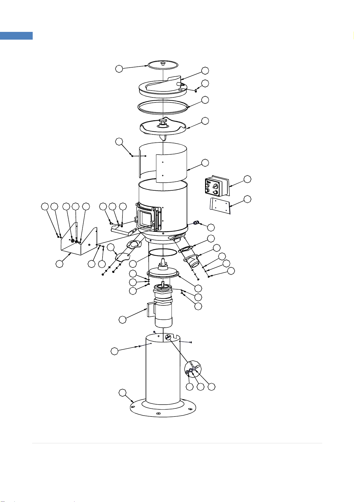
WASTE OUTLET CONNECTION
The peeler has two possible waste outlet locations. If it is required to change the waste outlet location,
remove both the existing waste outlet and the blanking plate on the opposite side. Refit both the waste
outlet and the blanking plate in their new positions.
A flexible hose, supplied with the machine, can be fitted over the waste outlet to direct the waste into
a gully or intercepting tank. If required, secure with the hose clip supplied. Longer lengths of flexible
hose are available from IMC on request.
The waste outlet also incorporates a 2”BSP female thread for connection to standard 54mm (2”) waste
pipe. DO NOT reduce the diameter of the waste pipe to below 54mm. The length of the pipe should
be kept to a minimum and the pipe must have a fall of at least 1:15. Changes of direction should be
made by swept bends rather than elbows and cleaning eyes should be fitted where possible in
accordance with standard plumbing practice.
A trap is not necessary if the discharge is into a gully or an intercepting tank, although a trap must be
provided in the outlet pipe from the intercepting tank. If a trap is required, it should be made with 45°
bends and not with a ‘U’or ‘P’bend or with a bottle trap.