IMC F79/060 User guide

1 | P a g e
Operating and Servicing Instructions
A34/073 R6 ECN 4825 April 2021
WASTESTATION AUTO FEED F79/060 &
REMOTE DEWATERER F78/061
Please make a note of your product details for
future use:
Date Purchased:_________________________
Model Number:__________________________
Serial Number:__________________________
Dealer:_________________________________
________________________________
_______

2 | P a g e
CONTENTS
INTRODUCTION.................................................................................................... 3
MODEL INFORMATION......................................................................................... 3
ON DELIVERY ....................................................................................................... 3
GUARANTEE......................................................................................................... 3
INSTALLATION OPTIONS..................................................................................... 4
FOR THE INSTALLER ........................................................................................... 4
SELECTION OF SITE............................................................................................ 4
MODEL IDENTIFICATION ..................................................................................... 4
SAFETY INSTRUCTIONS...................................................................................... 6
WORKING DIMENSIONS ...................................................................................... 8
WASTESTATION AF.............................................................................................. 8
REMOTE DEWATERER ........................................................................................ 9
CONTROLS AND INDICATIONS......................................................................... 11
OPERATION ........................................................................................................ 13
USER MAINTENANCE ........................................................................................ 14
DAILY CLEANING................................................................................................ 14
CLEANING CYCLE.............................................................................................. 15
CLEARING A JAM................................................................................................ 16
WIRING DIAGRAM .............................................................................................. 17
ORDERING SPARE PARTS................................................................................ 19
FURTHER INFORMATION .................................................................................. 19

3 | P a g e
INTRODUCTION
This machine is intended for the processing of food waste matter by maceration under an
automatic water flow, dewatering of the macerated food waste and discharge of the dewatered
food waste into a receptacle. The ‘grey’ water will be discharged into the drainage system.
MODEL INFORMATION
F79/060 WasteStation AF, 400 volt, 3-phase, 50/60 Hz
F78/061 Remote Dewaterer AF, 400 volt, 3-phase, 50/60 Hz
Please read these instructions carefully for trouble-free installation and operation.
Please observe these instructions carefully.
The guarantee applies in this form to installations within the United Kingdom. Contact your
WasteStation supplier first.
ON DELIVERY
Please check the contents against the following list and notify both the Carrier and Supplier
within 24 hours if anything is missing or damaged.
Fully assembled WasteStation with following items loose: -
Release key = 1 off
Waste bin (240Ltr) = 2 off
Instruction Manual = 1 off
Operating Plaque = 2 off (wall mounted self-adhesive)
Appliance hoses = 3 (2 x WS AF, 1 x DWR)
GUARANTEE
This machine is guaranteed by Lincat for 2 Year from the date of its purchase from Lincat, or
from one of its stockists, dealers or distributors. The guarantee is limited to the replacement of
faulty parts or products and excludes any consequential loss or expense incurred by
purchasers. Defects, which arise from faulty installation, inadequate maintenance, incorrect
use, and connection to the wrong electricity supply or fair wear and tear, are not covered by the
guarantee.
The guarantee applies in this form to installations within the United Kingdom only.

4 | P a g e
Please observe the following instructions carefully.
INSTALLATION OPTIONS
FOR THE INSTALLER
These Instructions contain important information designed to help the user obtain themaximum
benefit from the investment in an IMC WasteStation.
Please read them carefully before starting work, and consult with the supplier in the event of
any queries.
Be sure to leave this Instruction Manual with the user after the installation of the machine is
complete.
The machine is operated from the built-in control box.
SELECTION OF SITE
Select the site of the WasteStation with care so that it is convenient both for the major source
of food waste and for access by machine operators. The machine should be installed as close
to the existing drains as reasonably practicable.
MODEL IDENTIFICATION
The IMC WasteStation AF & Remote Dewaterer grey water macerator appliances are
for the use in commercial establishments only and are for permanent connection.
IMC WASTESTATION
The WasteStation AF comprises of the control cabinet, macerator and pump
assemblies with a hopper capacity of 200 litres.

5 | P a g e
The Remote Dewaterer comprises of a cabinet with a dewaterer unit and removable
240 litre capacity wheeled waste bin.
IMC REMOTE DEWATERER

6 | P a g e
SAFETY INSTRUCTIONS
All safety instructions detailed within this document are to be adhered to for safe
operation, of personnel and the equipment.
The following symbols are used on the product and throughout the product
documentation:
MEANING / DESCRIPTION
SYMBOL
SIGNIFICATION /
DESCRIPTION
WARNING/CAUTION
An appropriate safety
instruction should be
followed or caution to a
potential hazard exists.
AVERTISSEMENT
Une consigne de sécurité
appropriée doivent être
suivies ou garde d'un danger
potentiel existe.
PROTECTIVE EARTH (GROUND)
To identify any terminal which
is intended for connection to
an external conductor for
protection against electric
shock in case of a fault, or
the terminal of a protective
earth (ground) electrode.
TERRE DE PROTECTION
Pour marquer bornes
destinées à être raccordées à
un conducteur de protection
extérieur contre les chocs
éclectiques en cas de défaut
d’isolement, ou pour marquer
la borne de la terre de
protection
DANGEROUS VOLTAGE
To indicate hazards arising
from dangerous voltages.
TENSION DANGEREUSE
Pour indiquer les dangers
résultant des tensions
dangereuses.
HEAVY
This product is heavy and
reference should be made to
the safety instructions for
provisions of lifting and
moving.
LOURD
Ce produit est lourd et se
référer aux instructions de
sécurité pour les dispositions
de soulever et déplacer.

7 | P a g e
SAFETY INSTRUCTIONS (Continued)
•THIS PRODUCT IS TO BE INSTALLED BY A QUALIFIED IMC
APPOINTED INSTALLATION ENGINEER OBSERVING ALL LOCAL
AND REGIONAL CODES.
•ALL ELECTRICAL AND WATER SERVICES ARE TO BE ISOLATED
BEFORE CARRYING OUT ANY REMEDIAL WORK OR
MAINTENANCE TO THE IMC WASTE APPLIANCE.
•THE MACERATOR APPLIANCE CONTAINS NO USER
SERVICEABLE PARTS.
•ENSURE ALL WATER SUPPLY AND WASTE CONNECTIONS ARE
TIGHT BEFORE OPERATION.
•NEVER RUN THE UNIT WITHOUT WATER SUPPLY; SERIOUS
PUMP DAMAGE MAY OCCUR.
•DO NOT POUR HOT OILS/LIQUIDS INTO THE MACERATOR –THIS
COULD LEAD TO DAMAGE TO MACERATOR MOTOR SEALS.
•NEVER PUT HANDS OR OBJECTS OTHER THAN FOOD WASTE
INTO THE HOPPER CHUTE.
•DO NOT PUT STRING, CLOTH, PLASTIC, WIRE, GLASS, CORK OR
METAL OBJECTS INTO THE MACHINE.
•THE MACERATOR APPLIANCE IS RATED FOR 30% NON-
CONTINUOUS DUTY, (18 MINUTES PER HOUR). –issue, 200 kg
waste takes approx. 1 hour to process therefore 60 minutes of use
per 3 hours 20 minutes.
•IN THE EVENT OF A FAULT OR AN EMERGENCY, ISOLATE BOTH
THE ELECTRICAL AND WATER SUPPLIES. THE IMC WASTE
APPLIANCE IS PROVIDED WITH AN ELECTRICAL ISOLATOR.
•THE IMC WASTE APPLIANCE IS FITTED WITH AN EMERGENCY
STOP. THIS SHOULD NOT BE USED TO ISOLATE THE MACHINE.
•THE EMERGENCY STOP BUTTON MUST NOT BE USED AS A
GENERAL ‘STOP’ BUTTON; SERIOUS BLOCKAGES MAY OCCUR.
•ENSURE METALLIC OBJECTS SUCH AS CUTLERY ETC. ARE NOT
EMPTIED INTO THE HOPPER. IF THEY ARE, THEY MUST BE
REMOVED BEFORE STARTING THE MACHINE.
8 | P a g e
•EGG AND CRAB SHELLS MUST NOT BE MACERATED IN BULK, ONLY
TO BE MIXED WITH OTHER FOOD WASTE
THIS CAN CAUSE SERIOUS MACHINE DAMAGE.
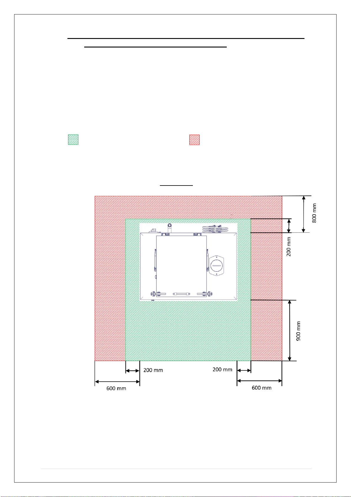
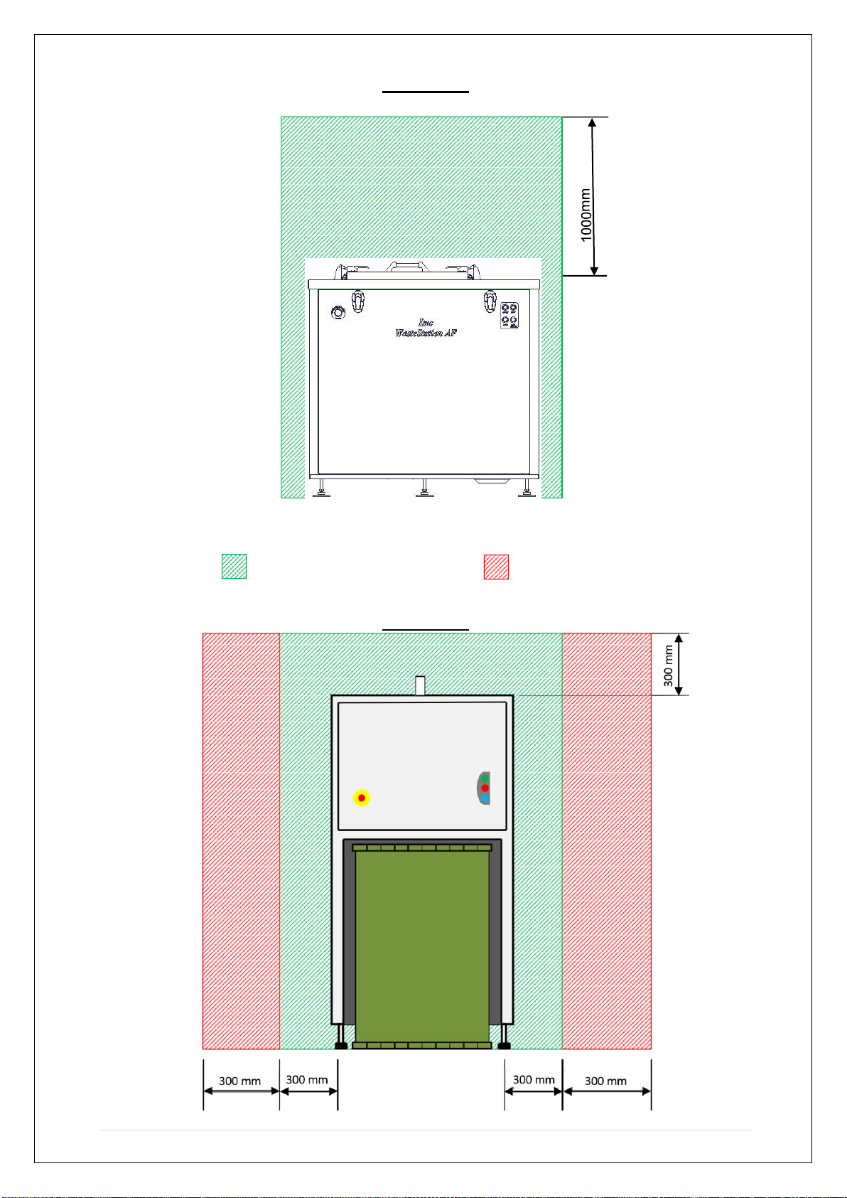
WORKING DIMENSIONS
The following clearances are required for safe operation of the WasteStation
AF appliance and Remote Dewaterer; and also for servicing:
Clearance required for normal Recommended Clearance
required operation for Service Engineer functions
WasteStation AF Plan View
9 | P a g e
Front View
Remote Dewaterer
Clearance required for normal Clearance required
Recommended operation for Service Engineer
functions Front View

10 | P a g e
Plan View
CAUTION:
Controls and Indications should not be obstructed
mm
600
mm
300
mm
300
600
mm

11 | P a g e
CONTROLS AND INDICATIONS
The WasteStation AF is easy to use; this section details the controls and
indications of the WasteStation AF & Remote Dewaterer.
The WasteStation AF & Remote Dewaterer appliances are provided with an
electrical isolator. The isolator is located at the rear of the WasteStation AF, the
Remote Dewaterer does not have a separate isolator as it is provided with all its
power signals by the WasteStation AF and so by isolating the WasteStation AF; it
also isolates the Remote Dewaterer.
Each unit is also provided with an emergency stop button, located on the front
panel of each unit.
The control panel on the WasteStation AF comprises of four illuminated buttons to
operate the machine and their function is described below; the buttons are
replicated on the Remote Dewaterer as indicator lights only:
BUTTON/
LAMP
ACTION
INDICATOR LIGHT (STATUS)
Solid
Flashing
Green
Cycle START
Cycle running
Cycle stopping
Red
Cycle STOP
Bin not in position
Bin full (nearing full
with siren, see
below)
Blue
Cleaning cycle
START
N/A
Cleaning cycle in
progress
Yellow
Auger feed
reverse
START
Feed reversing (to
prevent food jams)
N/A

12 | P a g e
The Green button will START a waste cycle.
The Red button will STOP a waste cycle. The red
indicator provides a collection bin status.
The Blue button starts and provides an indication of the
cleaning cycle.
The Yellow button starts and provides an indication of the
reverse rotation of the auger feed screw to prevent
blockages.
To START a waste cycle, press the Green button.
The indicator will remain illuminated to show that the cycle
is active.
The indicator will flash indicating the cycle is shutting
down.
When the Yellow button is illuminated, this indicates the
direction of the auger feed is reversing.
To STOP the cycle, press the RED button.
A steady red indicator means that the waste collection bin
is not fitted.
A flashing red indicator AND a siren means that the waste
collection bin is nearing fill level.
WARNING!–STOP FEEDING THE MACERATOR
INSTANTLY!
This is essential to prevent blockages. The siren will
cease after 2 seconds and the machine will stop after a
timed period.
When the Yellow button is illuminated, this indicates the
auger feed direction is reversed to prevent blockages.

13 | P a g e
To start a cleaning cycle, press the Blue button
The indicator will flash during the cycle and will stop
flashing when the cleaning cycle has finished.
When the Yellow button is illuminated, this indicates the
direction of the auger feed is reversing to help prevent
blockages.
OPERATION
•For safe operation refer to the Safety Instructions detailed
within this manual.
The macerator appliance is not for continuous duty and should be used for
18 minutes per hour. –issue, 200 kg waste takes approx. 1 hour to process
therefore 60 minutes of use per 3 hours 20 minutes.
DO NOT leave the macerator unattended while in operation.
In the event of an emergency only, use the emergency stop button
provided, isolate both the electrical and water supplies.
If the emergency stop is activated with food waste flowing through the
system, (if possible) the problem should be addressed IMMEDIATELY and
the system should be restarted to prevent waste from settling in the
pipework. If waste settlement occurs, flushing may be needed to help clear
the pipework before restarting, this is to help prevent a blockage.
Operation of the WasteStation AF / Dewaterer appliance is relatively straight
forward.
A. Ensure that the electrical isolator is set to ON and that the water supply
is available.
B. Ensure the collection bin is in position in the Remote Dewaterer for the
collection of the processed waste.
C. Feed accepted waste into the hopper –if unsure, refer to the manual
for accepted and non-accepted types of waste. Fully secure the lid.
D. At the control panel, press the GREEN button to START. This
activates the start-up sequence. Allow the system to fully start before
proceeding to the next step.
E. When the machine has finished processing the food waste, press the
RED button located on the control panel to STOP the cycle.
14 | P a g e
NOTE: The stop cycle time will be in accordance to the installation type and will be
set on commissioning. The green indicator will flash during this period.
The stop cycle has to be allowed to run its course to flush the full system of food
waste.
USER MAINTENANCE
The WasteStation AF / Remote Dewaterer appliance is of low maintenance.
CAUTION: Before carrying out any maintenance task(s), isolate the
electrical power.
The appliance requires daily cleaning only as described below.
DAILY CLEANING
DO NOT use a pressure washer.
Pouring a bucket of warm (NOT HOT), soapy water into the hopper at the end of
each day will help clean the equipment and disperse any residual solids in the
piping. Using the warm, soapy bucket of water, gradually pour the contents along
the internal sides of the hopper and along the auger screw.
If needed, use a ‘dishwashing type brush’ and brush off any deposits of food
necessary.
Wipe over the exterior of the machine, including the back areas that are not
normally visible. Proprietary cleaners may safely be used but avoid particularly
aggressive cleaners and neat bleach solutions.
A cleaning cycle should now be carried out.

15 | P a g e
CLEANING CYCLE
Following the standard daily cleaning routine, the automated cleaning cycle should
also be run.
NOTE: (The Remote Dewaterer needs to be on).
Ensure the power and water supplies are ON.
Press the BLUE button at the control panel to start the cleaning process. Allow the
appliance to complete the cleaning cycle.

16 | P a g e
FAULT FINDING
WARNING:
In the unlikely event of a fault occurring, immediately
isolate the power and water supplies.
If the appliance develops a fault, stop the machine immediately and isolate both the
electrical and water supplies.
In an emergency situation only, the emergency stop button should be used. This
is located on both front panels of the WasteStation AF and Remote Dewaterer.
Pressing the emergency button stops both machines instantly, refer to important
notes in section 6.
NOTE: The emergency stop button should only be used to stop the machine in
an emergency. The red button found on the control box at the front of the
WasteStation AF should be used for routine stopping of the machine operation.
CLEARING A JAM
As a result of a jam occurring, the machine will stall and stop. If this occurs,
proceed as follows:
1. Switch off the machine at the mains or at the isolator switch on the rear panel.
2. Unscrew the macerator lid.
3. Engage the prongs of the release key into the vanes of the rotor and exert
pressure in either direction (i.e. clockwise & anti-clockwise) to free the
blockage.
4. Check that the rotor is free to rotate 360°in both directions and if so, withdraw
the release key, screw down the macerator lid. (If there is still some resistance
when rotating, then repeat steps 3-4 until the jam is cleared).
5. Restore power to the machine and check normal operation by pressing the
green button.

17 | P a g e
WIRING DIAGRAM

18 | P a g e
Machine does not start
Cause
Action
Electrical supply is not turned on.
Switch on supply.
The mains isolator has tripped.
Call site electrician to reset the isolator. If
problem persists contact service personnel.
Waste bin is full (flashing red light)
Empty and then replace the bin
Waste bin is out of position (solid red light)
Replace the bin in its correct position inside the
bin enclosure on the machine.
Baffle is not correctly fitted.
Check baffle is in position and secured. If
problem persists contact service personnel.
One of the motor overload relays has tripped.
Rectify the problem then reset the overload
relay.
Emergency stop button has been pressed.
Deal with the emergency then reset the button
by turning it clockwise as shown on the button.
Unexpected system stop
Cause
Action
Electrical supply turned off.
Switch on supply.
The mains isolator has tripped.
Call site electrician to reset the isolator. If
problem persists contact service personnel.
Waste bin is full (flashing red light)
Empty and then replace the bin
Waste bin is out of position (solid red light)
Replace the bin in its correct position inside the
bin enclosure on the machine.
Baffle is not correctly fitted.
Check baffle is in position and secured. If
problem persists contact service personnel.
Motor overload has tripped.
Allow motor to cool for 10 minutes and restart.
If problem persists contact service personnel.
Emergency stop button has been pressed.
Deal with the emergency then reset the button
by turning it clockwise as shown on the button.
Waste jammed in disposer grinding unit.
Remove blockage from grinding unit.
See instructions on page 3.
Waste not processed
Cause
Action
A blockage has occurred in the waste pipe.
Clear blockage from waste pipe.
Slurry in Bin
Cause
Action
Feeding too quickly.
Allow to clear and feed more slowly.

19 | P a g e
ORDERING SPARE PARTS
In the event that spare parts or accessories need to be ordered, please always quote the
SERIES AND SERIAL NUMBER of the machine. This is to be found on the rating plate
located near the supply cable.
For installations outside the UK please contact your supplier.
For information on IMC spares and service support (if applicable), please call Lincat on +44
(0) 1522 875520. Alternatively, contact us via email:
Lincat Spares Desk E-mail: spar[email protected]o.uk
Lincat Limited
Whisby Road,
Lincoln, LN6 3QZ,
United Kingdom
Tel: +44 (0)1522 875500
E-mail: [email protected]
Website: www.Lincat.co.uk
FURTHER INFORMATION
HTTPS://LINCAT.CO.UK/BRANDS/IMC
https://www.youtube.com/watch?v=1hSfEPKi-fg
This manual suits for next models
1
Table of contents
Other IMC Industrial Equipment manuals


