IMC ARGUSfit User manual

imcTest & Measurement GmbH • Voltastr.5 • 13355Berlin • Germany
© 2023 imcTest & Measurement GmbH
imc ARGUSfit
Getting started
Edition 1 - 2023-06-06

© 2023 imcTest & Measurement GmbH imc ARGUSfit - Getting started, Edition 1 - 2023-06-06
Page 2
Disclaimer of liability
The contents of this documentation have been carefully checked for consistency with the hardware and
software systems described. Nevertheless, it is impossible to completely rule out inconsistencies, so that we
decline to offer any guarantee of total conformity.
We reserve the right to make technical modifications of the systems.
Copyright
© 2023 imcTest & Measurement GmbH, Germany
This documentation is the intellectual property of imcTest & Measurement GmbH. imcTest & Measurement
GmbH reserves all rights to this documentation. The applicable provisions are stipulated in the "imc Software
License Agreement".
The software described in this document may only be used in accordance with the provisions of the "imc
Software License Agreement".
Open Source Software Licenses
Some components of imc products use software which is licensed under the GNU General Public License (GPL).
Details are available in the About dialog.
A list of the open source software licenses for the imc measurement devices is located on the
imcSTUDIO/imcWAVE/imcSTUDIO Monitor installation medium in the folder "Products\imc DEVICES\OSS" or
"Products\imc DEVICEcore\OSS" or "Products\imc STUDIO\OSS". If you wish to receive a copy of the GPL sources
used, please contact our Hotline.

© 2023 imcTest & Measurement GmbH imc ARGUSfit - Getting started, Edition 1 - 2023-06-06
Page 3
Notes regarding this document
This document is an excerpt from the manual of the device / the module.
This document provides important notes on using the device / the module. Safe working is conditional on
compliance with all safety measures and instructions provided. The manual is to be used as a kind of reference
book. You can skip the description of the modules you do not have.
Additionally, all accident prevention and general safety regulations pertinent to the location at which the device
is used must be adhered to.
These instructions exclusively describe the device, not how to operate it by means of the software!
If you have any questions as to whether you can set up the device / module in the intended environment, please
contact the imc hotline. The measurement system has been designed, manufactured and unit-tested with all due
care and in accordance with the safety regulations before delivery and has left the factory in perfect condition. In
order to maintain this condition and to ensure safe operation, the user must observe the notes and warnings
contained in this chapter and in the specific sections applicable to the concrete device. Never use the device
outside the specification.
This will protect you and prevent damage to the device.
Special notes
Warning
Warnings contain information that must be
observed to protect the user from harm or to
prevent damage to property.
Note
Notes denote useful additional information on a
particular topic.
Reference
A reference in this document is a reference in
the text to another text passage.

© 2023 imcTest & Measurement GmbH imc ARGUSfit - Getting started, Edition 1 - 2023-06-06
Page 4
Table of contents
Table of contents
1 General introduction ................................................................................................. 5
1.1 imc Customer Support / Hotline .................................................................................................... 5
1.2 Legal notices ................................................................................................................................... 5
1.3 Explanation of symbols .................................................................................................................. 8
1.4 Latest changes in content .............................................................................................................. 9
2 Safety ...................................................................................................................... 10
3 Assembly and connection ........................................................................................ 13
3.1 After unpacking... ......................................................................................................................... 13
3.2 Before commissioning .................................................................................................................. 13
3.3 Notes on connecting .................................................................................................................... 14
3.3.1 Precautions for operation ................................................................................................................................ 14
3.3.2 Click mechanism ............................................................................................................................................... 15
3.3.3 Power supply .................................................................................................................................................... 16
3.3.4 Fiber Converter ................................................................................................................................................. 18
3.3.5 UPS-NiMH ......................................................................................................................................................... 19
3.3.6 Powering on ...................................................................................................................................................... 23
3.3.7 Powering off ..................................................................................................................................................... 23
3.3.8 Remote control of the base unit ....................................................................................................................... 23
3.3.9 Internal data carrier.......................................................................................................................................... 24
3.3.10 LED display ARGFT-BASE ................................................................................................................................. 27
4 Maintenance and servicing ...................................................................................... 28
4.1 Maintenance and servicing .......................................................................................................... 28
4.2 Cleaning ........................................................................................................................................ 28
4.3 Storage ......................................................................................................................................... 28
4.4 Transport ...................................................................................................................................... 28
5 Start of operation Software / Firmware ................................................................... 29
5.1 Installation - Software .................................................................................................................. 29
5.1.1 System requirements ........................................................................................................................................ 29
5.2 Connect the device ....................................................................................................................... 29
5.3 Connecting via LAN in three steps ............................................................................................... 30
5.4 Firmware update .......................................................................................................................... 32
6 Pin configuration ..................................................................................................... 34
6.1 Power ............................................................................................................................................ 34
6.2 Remote ......................................................................................................................................... 34
6.3 Base Unit ...................................................................................................................................... 35
6.3.1 GPS ................................................................................................................................................................... 35
6.3.2 CANSAS ............................................................................................................................................................. 35
6.4 Measurement Modules ................................................................................................................ 36
6.4.1 UTI-6 ................................................................................................................................................................. 36
Index .......................................................................................................................... 38

© 2023 imcTest & Measurement GmbH imc ARGUSfit - Getting started, Edition 1 - 2023-06-06
Page 5
imc Customer Support / Hotline Chapter 1
1 General introduction
1.1 imc Customer Support / Hotline
If you have problems or questions, please contact our Customer Support/Hotline:
imcTest & Measurement GmbH
Hotline
(Germany):
+49 30 467090-26
E-Mail:
hotline@imc-tm.de
Internet:
https://www.imc-tm.com
International partners
For our international partners see https://www.imc-tm.com/distributors/.
Tip for ensuring quick processing of your questions:
If you contact us you would help us, if you know the serial number of your devices and the version info of the
software. This documentation should also be on hand.
·
The device's serial number appears on the nameplate.
·
The program version designation is available in the About-Dialog.
1.2 Legal notices
Quality Management
imcTest & Measurement GmbH holds DIN-EN-ISO-9001 certification
since May 1995. You can download the CE Certification, current
certificates and information about the imc quality system on our website:
https://www.imc-tm.com/quality-assurance/.
imc Warranty
Subject to the general terms and conditions of imcTest & Measurement GmbH.

© 2023 imcTest & Measurement GmbH imc ARGUSfit - Getting started, Edition 1 - 2023-06-06
Page 6
Legal notices Chapter 1
Liability restrictions
All specifications and notes in this document are subject to applicable standards and regulations, and reflect the
state of the art well as accumulated years of knowledge and experience. The contents of this document have
been carefully checked for consistency with the hardware and the software systems described. Nevertheless, it
is impossible to completely rule out inconsistencies, so that we decline to offer any guarantee of total
conformity. We reserve the right to make technical modifications of the systems.
The manufacturer declines any liability for damage arising from:
·
failure to comply with the provided documentation,
·
inappropriate use of the equipment.
Please note that all properties described refer to a closed measurement system and not to its individual slices.
Attach covers over the module connectors on the upper and lower sides.
Guarantee
Each device is subjected to a 24-hour "burn-in" before leaving imc. This procedure is capable of detecting almost
all cases of early failure. This does not, however, guarantee that a component will not fail after longer operation.
Therefore, all imc devices are granted liability for a period of two years. The condition for this guarantee is that
no alterations or modifications have been made to the device by the customer.
Unauthorized intervention in the device renders the guarantee null and void.
Notes on radio interference suppression
imc ARGUSfit devices satisfy the EMC requirements for an use in industrial settings.
Any additional products connected to the product must satisfy the EMC requirements as specified by the
responsible authority (within Europe1) in Germany the BNetzA - "Bundesnetzagentur" (formerly BMPT-Vfg. No.
1046/84 or No. 243/91) or EC Guidelines 2014/30/EU. All products which satisfy these requirements must be
appropriately marked by the manufacturer or display the CE certification marking.
Products not satisfying these requirements may only be used with special approval of the regulating body in the
country where operated.
All lines connected to the imc ARGUSfit should not be longer than 30m and they should be shielded and the
shielding must be grounded.
Note
The EMC tests were carried out using shielded and grounded input and output cables with the exception of
the power cord. Observe this condition when designing your experiment to ensure high interference
immunity and low jamming.
1 If you are located outside Europe, please refer the appropriate EMC standards used in the country of operation.
14
© 2023 imcTest & Measurement GmbH imc ARGUSfit - Getting started, Edition 1 - 2023-06-06
Page 7
Legal notices Chapter 1
Cables and leads
In order to comply with the value limits applicable to Class B devices according to part 15 of the FCC regulations,
all signal leads connected to imc ARGUSfit must be shielded.
Unless otherwise indicated, no connection leads may be long leads (<30m) as defined by the standard IEC
61326-1. LAN-cables (RJ 45) and CAN-Buscables are excepted from this rule.
Only cables with suitable properties for the task (e.g. isolation for protection against electric shock) may be
used.
ElektroG, RoHS 2, WEEE, CE
The imcTest & Measurement GmbH is registered with the authority as follows:
WEEE Reg. No. DE 43368136
valid from 24.11.2005
Reference
https://www.imc-tm.com/elekrog-rohs-weee/ and https://www.imc-tm.com/ce-conformity/
FCC-Notice
This product has been tested and found to comply with the limits for a Class B digital device, pursuant to Part 15
of the FCC Rules. These limits are designed to provide reasonable protection against harmful interference in a
residential installation. This equipment generates, uses, and can radiate radio frequency energy and, if not
installed and used in accordance with the instructions, may cause harmful interference to radio communications.
However, there is no guarantee that interference will not occur in a particular installation. If this equipment does
cause harmful interference to radio or television reception, which can be determined by turning the equipment
on and off, the user is encouraged to try to correct the interference by one or more of the following measures:
·
Reorient or relocate the receiving antenna.
·
Increase the separation between the equipment and the receiver.
·
Connect the equipment into an outlet on a circuit different from that to which the receiver is connected.
·
Consult our imc Hotline or an experienced technician for help.
Modifications
The FCC requires the user to be notified that any changes or modifications made to this product that are not
expressly approved by imc may void the user's authority to operate this equipment.

© 2023 imcTest & Measurement GmbH imc ARGUSfit - Getting started, Edition 1 - 2023-06-06
Page 8
Explanation of symbols Chapter 1
1.3 Explanation of symbols
CE Conformity
see CE chapter 1.2
No household waste
Please do not dispose of the electrical/electronic device with household waste, but at the
appropriate collection points for electrical waste, see also chapter 1.2 .
Potential compensation
Connection for potential compensation
Grounding
Connection for grounding (general, without protective function)
Protective connection
Connection for the protective conductor or grounding with protective function
Attention! General danger zone!
This symbol indicates a dangerous situation;
Since there is insufficient space for indicating the rated quantity at the measuring inputs,
refer to this manual for the rated quantities of the measuring inputs before operation.
Attention! Injuries from hot surfaces!
Surfaces whose temperatures can exceed the limits under certain circumstances are
denoted by the symbol shown at left.
ESD-sensitive components (device/connector)
When handling unprotected circuit boards, take suitable measures to protect against ESD
(e.g. insert/remove ACC/CANFT-RESET).
Possibility of electric shock
The warning generally refers to high measurement voltages or signals at high potentials and
is located on devices suitable for such measurements. The device itself does not generate
dangerous voltages.
DC, Direct Current
Supply of the device via a DC voltage source (in the specified voltage range)
5
5

© 2023 imcTest & Measurement GmbH imc ARGUSfit - Getting started, Edition 1 - 2023-06-06
Page 9
Explanation of symbols Chapter 1
RoHS of the PR China
The limits for hazardous substances in electrical/electronic equipment applicable in the PRC
are identical to those in the EU. The restrictions are complied with (see chapter 1.2 ). A
corresponding "China-RoHS" label is omitted for formal/economic reasons. Instead, the
number in the symbol indicates the number of years in which no hazardous substances are
released. (This is guaranteed by the absence of named substances).
Observe the documentation
Read the documentation before starting work and/or operating.
1.4 Latest changes in content
Please help us to improve our documentation:
Which terms or descriptions are incomprehensible?
What additions and enhancements you suggest?
Where have material mistakes slipped in?
Which spelling, translation or typing errors have you found?
Responses and other feedback should be directed to the Hotline
Completions and error remedies in the manual edition 1
Chapter
Change
5

© 2023 imcTest & Measurement GmbH imc ARGUSfit - Getting started, Edition 1 - 2023-06-06
Page 10
Chapter 2
2 Safety
This section provides an overview of all important aspects of protection of the users for reliable and trouble-free
operation. Failure to comply with the instructions and protection notes provided here can result in serious
danger.
Responsibility of the operator
imc ARGUSfit is for use in commercial applications. The user is therefore obligated to comply with legal
regulations for work safety.
Along with the work safety procedures described in this document, the user must also conform to regulations
for safety, accident prevention and environmental protection which apply to the work site. If the product is not
used in a manner specified by the manufacturer, the protection supported by the product may be impaired.
The user must also ensure that any personnel assisting in the use of the imc ARGUSfit have also read and
understood the content of this document.
Operating personnel
This document identifies the following qualifications for various fields of activity:
·
Users of measurement engineering: Fundamentals of measurement engineering. Basic knowledge of electrical
engineering is recommended. Familiarity with computers and the Microsoft Windows operating system. Users
must not open or structurally modify the measurement device.
·
Qualified personnel are able, due to training in the field and to possession of skills, experience and familiarity
with the relevant regulations, to perform work assigned while independently recognizing any hazards.
Warning
·
Danger of injury due to inadequate qualifications!
·
Improper handling may lead to serious damage to personnel and property. When in doubt, consult qualified
personnel.
·
Work which may only be performed by trained imc personnel may not be performed by the user. Any
exceptions are subject to prior consultation with the manufacturer and are conditional on having obtained
corresponding training.
© 2023 imcTest & Measurement GmbH imc ARGUSfit - Getting started, Edition 1 - 2023-06-06
Page 11
Chapter 2
Special hazards
This segment states what residual dangers have been identified by the hazard analysis. Observe the safety notes
listed here and the warnings appearing in subsequent chapters of this manual in order to reduce health risks and
to avoid dangerous situations. Existing ventilation slits on the sides of the device must be kept free to prevent
heat accumulation inside the device. Please operate the device only in the intended position of use if so
specified.
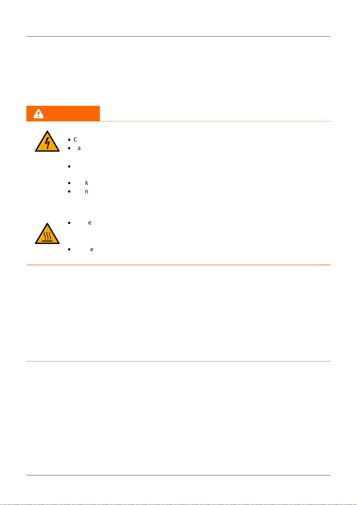
Danger
Lethal danger from electric current!
·
Contact with conducting parts is associated with immediate lethal danger.
·
Damage to the insulation or to individual components can be lethally dangerous.
Therefore:
·
In case of damage to the insulation, immediately cut off the power supply and have repair
performed.
·
Work on the electrical equipment must be performed exclusively by expert electricians.
·
During all work performed on the electrical equipment, it must be deactivated and tested for
static potential.
Injuries from hot surfaces!
·
Devices from imc are designed so that their surface temperatures do not exceed limits
stipulated in EN 61010-1 under normal conditions.
Therefore:
·
Surfaces whose temperature can exceed the limits under circumstances are denoted by the
symbol shown at left.
Industrial safety
We certify that imc ARGUSfit in all product configuration options corresponding to this documentation conforms
to the directives in the accident prevention regulations in "Electric Installations and Industrial Equipment" (DGUV
Regulation 3)*. This confirmation applies exclusively to devices of the imc ARGUS series, but not to all other
components included in the scope of delivery.
This certification has the sole purpose of releasing imc from the obligation to have the electrical equipment
tested prior to first use (§ 5 Sec. 1, 4 of DGUV Regulation3). This does not affect guarantee and liability
regulations of the civil code.
*
previously BGV A3.

© 2023 imcTest & Measurement GmbH imc ARGUSfit - Getting started, Edition 1 - 2023-06-06
Page 12
Chapter 2
Observe notes and warnings
Devices from imc have been carefully designed, assembled and routinely tested in accordance with the safety
regulations specified in the included certificate of conformity and has left imc in perfect operating condition. To
maintain this condition and to ensure continued danger-free operation, the user should pay particular attention
to the remarks and warnings made in this chapter. In this way, you protect yourself and prevent the device from
being damaged.
Read this document before turning on the device for the first time carefully.
Warning
Before touching the device sockets and the lines connected to them, make sure static electricity is diverted
to ground. Damage arising from electrostatic discharge is not covered by the warranty.

© 2023 imcTest & Measurement GmbH imc ARGUSfit - Getting started, Edition 1 - 2023-06-06
Page 13
After unpacking... Chapter 3
3 Assembly and connection
3.1 After unpacking...
Check the delivered system immediately upon receiving it for completeness and for possible transport damage.
In case of damage visible from outside, proceed as follows:
·
Do not accept the delivery or only accept it with reservations
·
Note the extent of the damage on the packing documents or on the delivery service's packing list.
·
Begin the claims process.
For an overview of the accessories supplied as standard, please refer to the data sheet of the supplied ARGUSfit
module. Check the accessories for completeness.
Note
File a claim about every fault as soon as it is detected. Claims for damages can only be honored within the
stated claims period.
3.2 Before commissioning
Condensation may form on the circuit boards when the device is moved from a cold environment to a warm
one. In these situations, always wait until the device warms up to room temperature and is completely dry
before turning it on. The acclimatization period should take about 2 hours.
Ambient temperature
The limits of the ambient temperature cannot be strictly specified because they depend on many factors of the
specific application and environment, such as air flow/convection, heat radiation balance in the environment,
contamination of the housing / contact with media, mounting structure, system configuration, connected cables,
operating mode, etc. This is taken into account by specifying the operating temperature instead. Furthermore, it
is not possible to predict any sharp limits for electronic components. Basically, reliability decreases when
operating under extreme conditions (forced ageing). The operating temperature data represent the extreme
limits at which the function of all components can still be guaranteed.
© 2023 imcTest & Measurement GmbH imc ARGUSfit - Getting started, Edition 1 - 2023-06-06
Page 14
Notes on connecting Chapter 3
3.3 Notes on connecting
3.3.1 Precautions for operation
Certain ground rules for operating the system, aside from reasonable safety measures, must be observed to
prevent danger to the user, third parties, the device itself and the measurement object. These are the use of the
system in conformity to its design, and the refraining from altering the system, since possible later users may not
be properly informed and may ill-advisedly rely on the precision and safety promised by the manufacturer.
Note
If you determine that the device cannot be operated in a non-dangerous manner, then the device is to be
immediately taken out of operation and protected from unintentional use. Taking this action is justified under
any of the following conditions:
I. the device is visibly damaged,
II. loose parts can be heard within the device,
III. the device does not work
IV. the device has been stored for a long period of time under unfavorable conditions (e.g. outdoors or in
high-humidity environments).
1. Observe the data in the manual chapter "Technical Specifications", to prevent damage to the unit through
inappropriate signal connection.
2. Note when designing your experiments that all input and output leads must be provided with shielding
which is connected to the ground ("CHASSIS") at one end in order to ensure high resistance to
interference and noisy transmission.
3. Unused, open channels (having no defined signal) should not be configured with sensitive input ranges
since otherwise the measurement data could be affected. Configure unused channels with a broad input
range or short them out. The same applies to channels not configured as active.
4. If you are using a removable storage media, observe the notes in the imc software manual.
Particular care should be taken to comply with the storage device's max. ambient temperature limitation.
5. Avoid prolonged exposure of the device to sunlight.
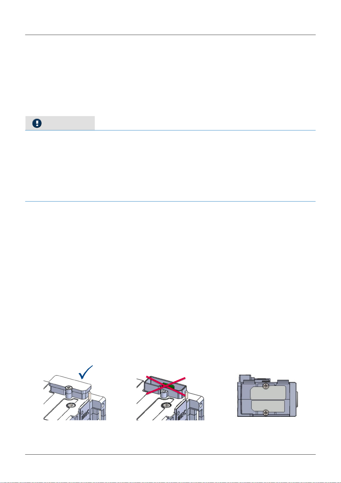
Due to their function, the imc ARGUSfit modules, just like the CANSASfit modules, are open at the connection
points (module connectors). This is not a problem when used in a controlled, dry environment. In order to
protect a module (or even a group connected in series) against foreign objects and moisture, please carry out
the following measure:
Attach covers over the module connectors on the upper and lower sides.
Two covers per module are fixed at the left side of the module (parking position).
Fig. 1: parking position of
covering caps
module connector protected
with covering cap
module connector
not protected
© 2023 imcTest & Measurement GmbH imc ARGUSfit - Getting started, Edition 1 - 2023-06-06
Page 15
Notes on connecting Chapter 3
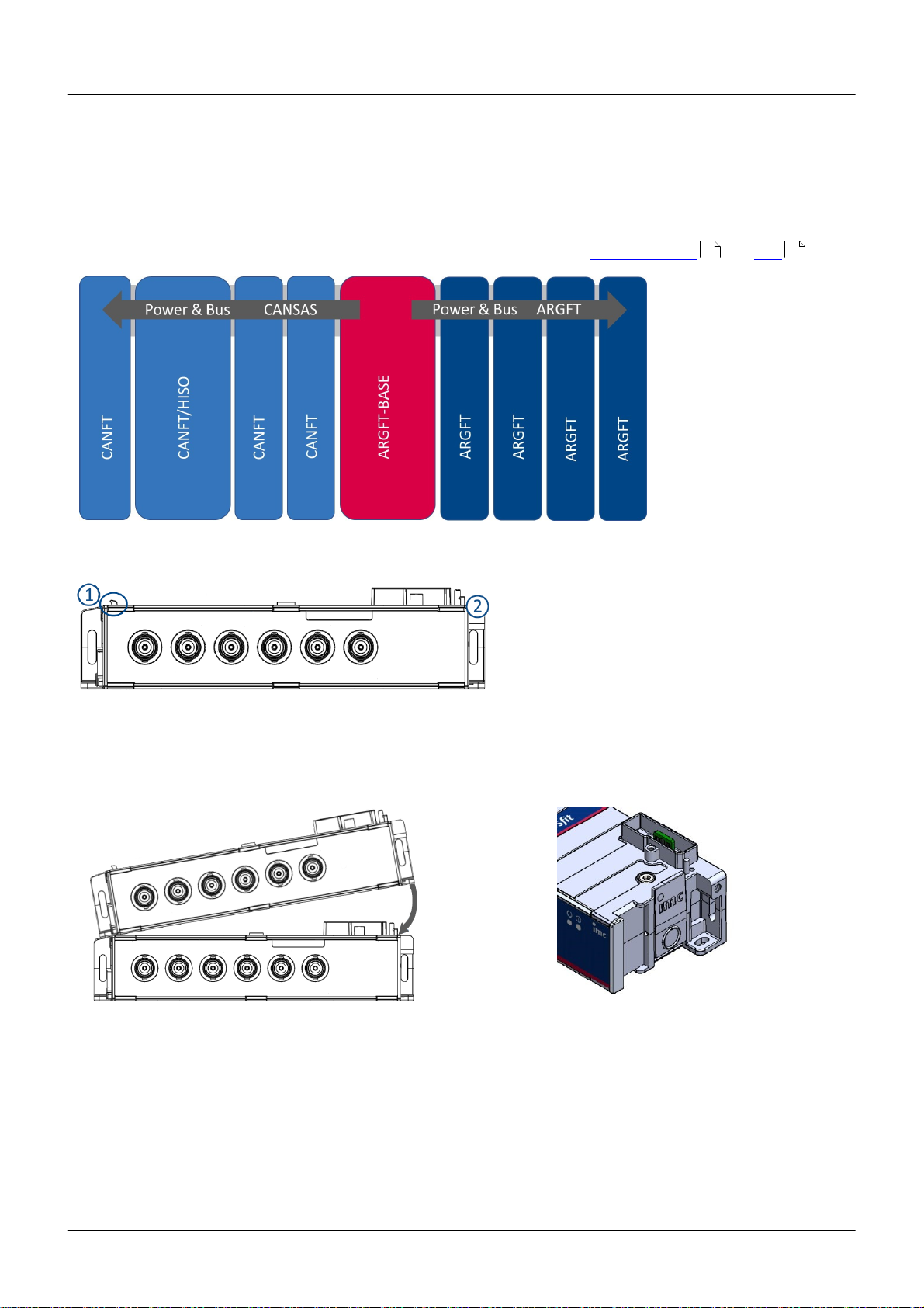
3.3.2 Click mechanism
imc ARGUSfit (ARGFT) modules and imc CANSASfit (CANFT) modules can be mechanically and electrically
connected by a click-lock, without tools and without additional connecting cables.
The CANFT Module are connected
to the system on the left side of the
ARGFT base unit, see Fig. 2.
ARGFT
base unit
ARGFT modules are connected to the system on the
right side of the ARGFT base unit.
Further rules, see Fiber converter and UPS
Fig. 2: Order of possible Click connections
Fig. 3: Locking tongue & locking latch
Stacking the modules
1. Hook tongues into the grooves, see Fig. 3 Position (1) "tongue".
2. Press modules together
Fig. 4: locking latch
3. To finish mechanical connection, press on the imc Logo (2) on the locking latch. You will hear a click.
Now the modules are mechanically locked and electrically connected.
Removing modules from the stack
1. Press the circle on the locking latch, see Fig. 4.
You will hear a click.
2. Pull tongues, see Fig. 3 position (1) out of the grooves.
18 19
© 2023 imcTest & Measurement GmbH imc ARGUSfit - Getting started, Edition 1 - 2023-06-06
Page 16
Notes on connecting Chapter 3
3.3.3 Power supply
An imc ARGUSfit system can be operated with a DC supply voltage that is fed to the overall system via a socket
compatible with LEMO.EGE.0B.302 on the base unit ("POWER").
The permissible supply voltage range is 10 to 50 V DC (ultra-wide range). For the AC/DC adapter ("desktop
power supply") supplied with the base unit, the specified AC voltage range on the input side is 110 V.. 240 V
50/60 Hz. With regard to EN 61326-1 and EN 61010-1, the DC supply inputs are not specified for connection to a
DC mains supply.
Connecting a DC supply source such as a car battery is also fundamentally possible. Please note when making
such a connection:
·
Grounding of the imc ARGUSfit system must be provided. If the supply voltage source has a ground
reference (ground connection to the (-)terminal, then the device is automatically grounded via the (-)
terminal. The supplied power adaptor is prepared in this way.
·
The supply line must be of low impedance via a cable with a sufficient cross-section. Any (interference
suppression) filters (interference suppression) filters in the supply circuit should not contain series
inductances greater than 1mH. should be present. Otherwise, an additional parallel capacitor is necessary.
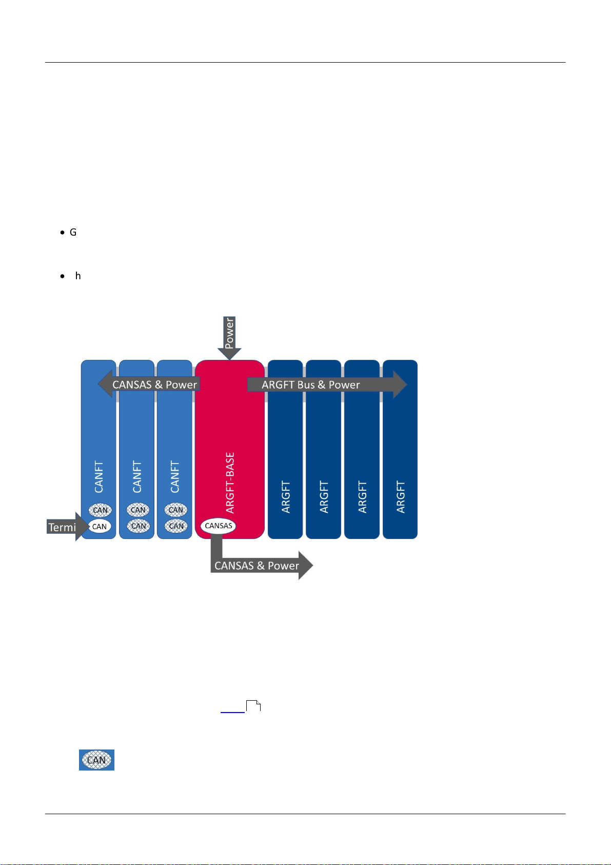
Fig. 5: Power supply via ARGFT base unit
Left
Base
Right
all CANSASfit modules
ARGUSfit Base
all ARGUSfit modules
(CANFT modules)
CANFT
CAN node 1 is available on the ARGFT base unit for connecting CANFT modules
via a LEMO cable. The 5-pin LEMO socket on the base unit is marked:
"CANSAS". The CANFT modules connected via this LEMO socket are directly
supplied by the ARGFT system supply (is not related to CAN-GND),
see Fig. 6 . A further supply of the CANFT modules is not necessary and
must not be carried out (see CANFT topology in the section Commissioning of
the imcCANSAS - Modules and Software Manual).
The external CAN connections of the CANFT modules "clocked on" to the base unit (CAN
node2) are switched off, see Fig. 5.
17

© 2023 imcTest & Measurement GmbH imc ARGUSfit - Getting started, Edition 1 - 2023-06-06
Page 17
Notes on connecting Chapter 3
Fig. 6: Power supply of ARGFT and CANFT
Notes
·
Termi:
The CAN terminator 120 Ω, LEMO.0B plug (ACC/CANFT-TERMI, 13500242) must only be connected to the
CANFT module block, which is connected to the base unit (CANSAS) via a LEMO cable, see Fig. 6. The
CANFT modules directly coupled to the ARGFT base unit are automatically terminated via ARGFT and do
not require a termi.
·
Note that the operating temperature of the power supply adaptor is designed for 0 °C to 40 °C. This also
applies if your unit should be suitable for an extended temperature range.
·
When connecting the power supply, please note that the supply line must be of low impedance via a
cable with a sufficient cross-section. Any additional (interference suppression) filters connected in the
supply circuit should not contain series inductances greater than 1 mH. Otherwise, an additional parallel
capacitor is necessary.
References
·
Technical details concerning ARGFT power supply, see manual chapter "Technical Specs" and
you can find the pin configuration in chapter "Power"
·
For an application with the Fiber converter, see chapter "Fiber converter" .
·
For an application with the Power supply (UPS-NiMH) module, see chapter "UPS-NiMH" .
34
18
19
© 2023 imcTest & Measurement GmbH imc ARGUSfit - Getting started, Edition 1 - 2023-06-06
Page 18
Notes on connecting Chapter 3
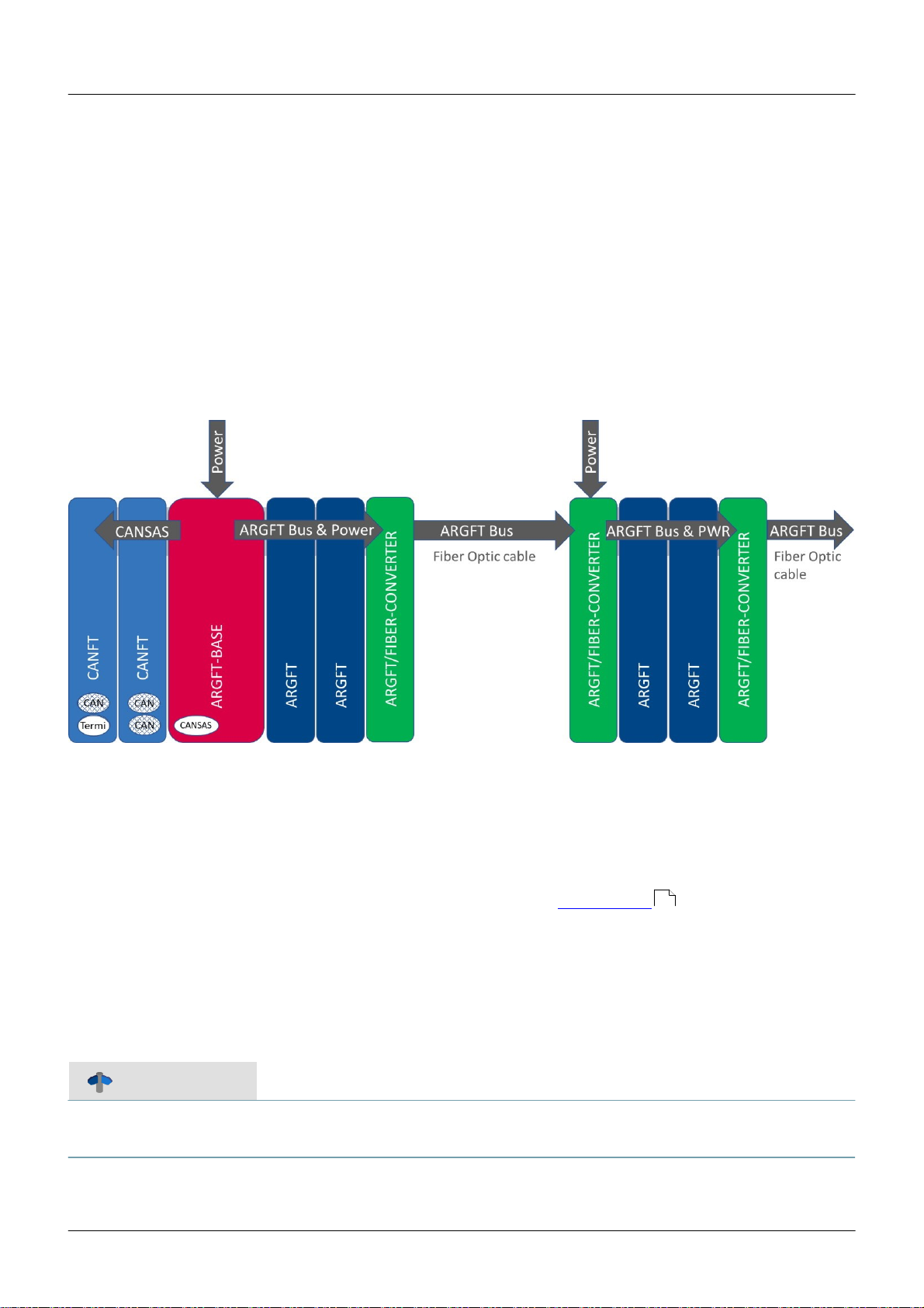
3.3.4 Fiber Converter
The Fiber Converter is a clickable module for the modular imc ARGUSfit system. It allows decentralized
distributed system topologies.
The module converts the internal high-speed ARGUS system bus, which connects the ARGUS measurement
amplifier and interface modules via the click connector, to a fiber-optic data link in the sense of a media
converter. Thus, the click connection can be extended to a spatially distributed arrangement of the entire ARGUS
system by a pair of converters (master/slave) and a fiber optic cable.
The remote module block uses a joint power supply at is fed into the slave converter module.
Fiber converter application
One fiber converter each is clicked onto the right (master) or left (slave) side of an imc ARGUSfit module block.
The converters have a uniform design and recognize their master/slave function automatically:
Base unit block
Master converter
Satellite block #1
further #2..n
The voltage supply of the base block is realized via the supply socket of the base unit. The power supply of the
satellite block (ARGFT module block #1) and possibly further module blocks #2..n is realized via the supply socket
of the slave fiber converters clicked onto these module blocks. For this purpose, a DC supply voltage or an AC/DC
mains adapter must be connected to the LEMO.0B (2-pin) "POWER" socket of the converter (optional accessory).
For these module blocks #2..n, the same specified AC voltage range applies on the input side, as well as the note
regarding EN 61326-1 and EN 61010-1 as for the base unit in chapter "Power supply ".
If the slave fiber converter detects no signal activity via the connected fiber cable, it deactivates the power
supply of the clicked modules and the slave fiber converter is in sleep mode with reduced power consumption. If
signal activity is detected, the power supply for the clicked modules is switched on. Thus, switching off the base
unit always leads to switching off the satellite module blocks as well, and the slave fiber converters are put into
sleep mode.
Reference
Technical specs for the Fiber Converter, see manual chapter "Technical Specs".
LED functionalities of the Fiber Converter, see manual chapter "Technical Specs / Status- and Power LED".
16
© 2023 imcTest & Measurement GmbH imc ARGUSfit - Getting started, Edition 1 - 2023-06-06
Page 19
Notes on connecting Chapter 3
3.3.5 UPS-NiMH
Powering on/off
The supply module (ARGFT/UPS-NIMH) switches on when
·
the module's own pushbutton is pressed and an external supply is applied via the "POWER IN" socket at the
same time.
·
a pushbutton connected to the module's own "REMOTE" socket is pressed and at the same time an
external supply is applied via the "POWER IN" socket.
·
a switch connected to the module's own "REMOTE" socket is closed and an external supply via the "POWER
IN" socket is applied at the same time.
An imc ARGUSfit-BASE connected to the power supply module receives a shutdown command via the plugged
"REMOTE" accessory cable during operation or the power supply module switches off without an imc ARGUSfit-
BASE connected when / if
·
the module's own button is pressed.
·
a button connected to the module's own remote socket is pressed.
·
a switch connected to the module's own remote socket is opened.
·
if an overload case occurs (for details see section "Output power" and section "Output-side overcurrent
protection" ).
·
if the UPS buffer duration has expired or the battery is completely discharged in battery mode.
The supply module switches off with the imc ARGUSfit-BASE connected if
·
the imc ARGUSfit-BASE, after being active, has been shut down and has switched itself off.
·
the imc ARGUSfit-BASE has still not switched itself off 20 seconds after a shutdown command (error case
with the imc ARGUSfit-BASE).
If the power supply module does not respond to all attempts to switch it off, it can be switched off by pressing
the module's button for at least 4seconds. This prevents damage to the batteries due to deep discharge.
Reference
For the power supply module, the same specified voltage range applies on the input side, as well as the
note regarding EN 61326-1 and EN 61010-1 as for the base unit in chapter "Power supply ".
Remote socket
The supply module has a "REMOTE" socket for switching the supply module on and off and a "REMOTE OUT"
socket for switching an imc ARGUSfit base unit on and off.
The assignment of the "REMOTE" socket is identical to the assignment of other imc supply modules (e.g. imc
CRFX/HANDLE-xxx). A static switch (between pin1 and pin2) or a push button (between pin3 and pin4) can be
connected for switching on and off.
A jumper between GND (pin1/3/5) and -MUTE (pin6) can be used to mute the internal buzzer of the supply
module for buffer operation.
In order for the supply module to switch the imc ARGUSfit-BASE on and off, the corresponding accessory cable
must be connected between "REMOTE OUT" and the "REMOTE" socket on the imcARGUSfit-BASE, see Fig. 7 .
20
20
16
34
20

© 2023 imcTest & Measurement GmbH imc ARGUSfit - Getting started, Edition 1 - 2023-06-06
Page 20
Notes on connecting Chapter 3
Output voltage for connecting the imc ARGUSfit-BASE and additional measuring modules.
The supply module passes the external supply voltage unregulated to the output. In buffer mode, the internal
battery voltage is regulated to approx. 12 V and applied to the output. The supply module has three "POWER
OUT" sockets connected in parallel, to which the output voltage for the connected devices is applied. The
available output power of the module is divided between all three connections. The assignment is identical with
the "POWER IN" socket. In order for the supply module to supply the imcARGUSfit-BASE, the corresponding
accessory cable must be connected between "POWER OUT" and the "POWER" socket on the imcARGUSfit-BASE,
see Fig. 7 .
Fig. 7: Power supply via ARGFT/UPS-NIMH (power supply module)
Output power
The supply module has an extended wide range input of 10..50VDC. In this range an output power of 50W is
available. Below 10VDC it is switched to battery operation. At low temperatures, the performance of the
accumulators is limited, which means that the full output power may not be available in the buffer case. It is
reduced by 1W/K below +15°C.
Output-side overcurrent protection
Since theoretically any number of modules could be connected to the supply module, the supply module has
two independent current limiting circuits to protect the internal circuitry:
1. short-circuit protection (reaction time 10..30ms)
2. static overload protection (reaction time approx. 1s)
The short-circuit protection limits the output current to a resulting output power of typically approx. 70..85W,
depending on the output voltage. If this limit is exceeded, the output voltage is cut after approx. 10..30ms and is
only enabled again after approx. 4 seconds. If the short-circuit has not been eliminated then, another 4 seconds
are waited and so on. During this "waiting" the "LIMIT" LED of the supply module flashes red every second.
The overload protection measures the output power every second, evaluates it and will shut down the system in
case of a static overload. If the permissible static output power of 50 W is exceeded, a shutdown process is
initiated after 10 seconds (after 1 second in the buffer case). The "LIMIT" LED lights up yellow at an output
power > 80 % and red at an output power > 95 % of the maximum permissible static output power.
20
Table of contents
Other IMC Industrial Equipment manuals


