imes-icore CORiTEC 350i Series User manual
Article number:
51100X X350
Original
Operating manual
Date created:
December 11, 2019
Operating manual
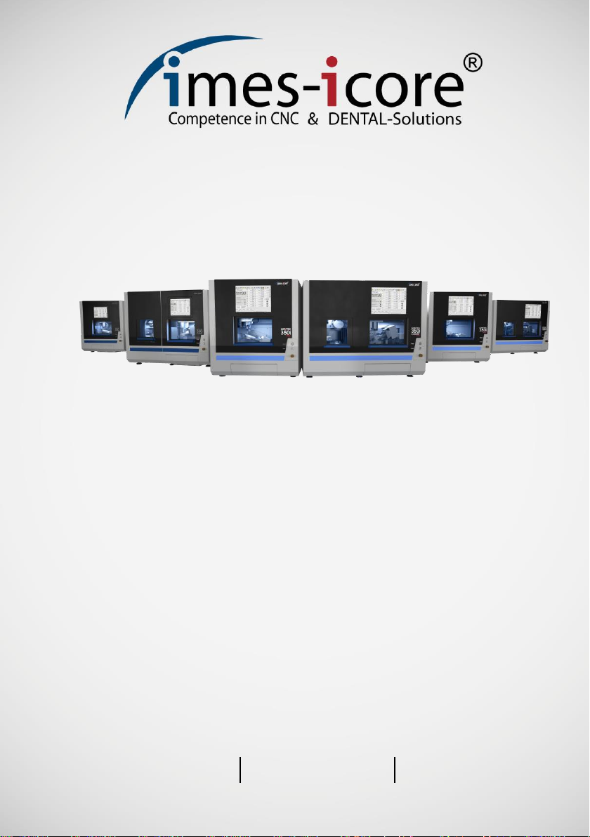
CORiTEC 350i series
CNC-Machine


Table of contents
1Basic guidelines....................................................................................................9
1.1 About using this operating manual...........................................................................9
1.2 Explanation of the machine types and designations.................................................9
1.2.1 Overview of the respective chapters......................................................................10
1.2.2 Explanation of the warning and information fields ..................................................11
1.2.3 Explanation of symbols..........................................................................................12
1.2.4 Symbols on the packaging.....................................................................................14
1.2.5 Symbols on the device...........................................................................................15
1.3 Information about this operating manual................................................................15
1.4 Limitations of liability..............................................................................................16
1.5 Copyright...............................................................................................................16
1.6 Trademark protection.............................................................................................16
1.7 Guarantee .............................................................................................................17
1.8 Technical modifications .........................................................................................17
1.9 Warranty Milling spindle.........................................................................................17
1.10 Accessories and modifications...............................................................................17
1.11 Contact..................................................................................................................18
1.11.1 Manufacturer.........................................................................................................18
1.11.2 Customer service...................................................................................................18
2For your safety.....................................................................................................19
2.1 Responsibility of the operator ................................................................................19
2.2 Information about the intended use........................................................................20
2.3 Brief description.....................................................................................................20
2.4 Intended use..........................................................................................................21
2.5 Residual risks and fundamental dangers ...............................................................22
2.5.1 Reasonably foreseeable misuses ..........................................................................23
2.5.2 Danger due to electrical energy.............................................................................24
2.5.3 Mechanical hazards...............................................................................................25
2.5.4 Dangers due to high temperatures.........................................................................25
2.5.5 Danger of fire.........................................................................................................26
2.5.6 Substance hazards (dust)......................................................................................27
2.5.7 Substance hazards (vapours)................................................................................27
2.5.8 Noise/sound emissions..........................................................................................28
2.5.9 Freeing a trapped person.......................................................................................28
2.5.10 In case of emergency ............................................................................................28
2.5.11 In case of fire.........................................................................................................29
2.6 Personnel requirements.........................................................................................29
2.6.1 Qualifications.........................................................................................................30
3Description of the machine.................................................................................31
3.1 Materials................................................................................................................31
3.2 Cooling lubricant CORiTEC mill & grind liquid........................................................32
3.3 Milling tools............................................................................................................32
3.4 Permissible milling tools.........................................................................................32
4Technical data......................................................................................................33
4.1 CORiTEC 350i series ............................................................................................33
4.2 CORiTEC 350i (Loader).........................................................................................34
4.3 CORiTEC 350i (Loader) PRO................................................................................35
4.4 CORiTEC 350i (Loader) PRO +.............................................................................36
4.5Ambient and installation conditions........................................................................36
4.6 Requirement for a compressed air connection.......................................................37
4.6.1 Air purity................................................................................................................37
4.7 Emissions..............................................................................................................37

4.7.1 Noise emissions....................................................................................................37
4.8 Type plate............................................................................................................. 38
5Structure and views............................................................................................ 39
5.1 Front view .............................................................................................................39
5.1.1 CORiTEC 350i (PRO) (+)...................................................................................... 39
5.1.2 CORiTEC 350i Loader (PRO) (+).......................................................................... 40
5.2 Side view left.........................................................................................................41
5.2.1 CORiTEC 350i (PRO) (+)...................................................................................... 41
5.2.2 CORiTEC 350i Loader (PRO) (+).......................................................................... 42
5.3 Side view, right......................................................................................................43
5.3.1 CORiTEC 350i (Loader) (PRO).............................................................................43
5.3.2 CORiTEC 350i (Loader) PRO + ............................................................................44
5.4 Rear view..............................................................................................................45
5.4.1 CORiTEC 350i (PRO) (+)...................................................................................... 45
5.4.2 CORiTEC 350i Loader (PRO) (+).......................................................................... 46
5.5 Tool magazine (direct changer).............................................................................47
5.5.1 CORiTEC 350i (PRO) (+)...................................................................................... 47
5.5.2 CORiTEC 350i Loader (PRO) (+).......................................................................... 48
5.6 View of Loader area.............................................................................................. 49
5.7 Buttons and switches (front side)........................................................................... 50
5.8 Connection panel..................................................................................................51
5.8.1 CORiTEC 350i Loader (PRO)................................................................................51
5.8.2 CORiTEC 350i (Loader) PRO + ............................................................................52
5.9 Supply connections...............................................................................................53
5.10 Maintenance unit...................................................................................................54
5.11 Cooling lubricant system .......................................................................................55
5.12 Cooling lubricant tank............................................................................................56
5.13 Ionizer device........................................................................................................57
5.14 View axle structure................................................................................................58
5.15 Coordinate system................................................................................................58
5.16 Assignment of the movement axes........................................................................ 58
5.17 Safety equipment on the machine......................................................................... 59
5.17.1 EMERGENCY STOP switch.................................................................................. 59
5.17.2 Protection and access doors .................................................................................60
5.17.3 Separating door inside ..........................................................................................62
5.17.4 Protective door monitoring.....................................................................................63
5.17.5 Protective door lock...............................................................................................63
5.17.6 Cover button ......................................................................................................... 63
5.18 Working and hazard area...................................................................................... 63
5.18.1 Working area......................................................................................................... 63
5.18.2 Hazard area..........................................................................................................63
5.19 Safety equipment that the operator might have to retrofit.......................................64
6Transport and packaging.................................................................................... 65
6.1 Safety instructions for transport.............................................................................65
6.1.1 Improper transport................................................................................................. 65
6.1.2 Eccentric centre of gravity.....................................................................................66
6.2 Transporting pallets............................................................................................... 66
6.3 Transport locks......................................................................................................66
6.4 Carry handles (transport aid)................................................................................. 66
6.5 Packaging.............................................................................................................67
6.6 Handling packaging materials ...............................................................................67
6.7 Standard scope of delivery.................................................................................... 68
7Installation and first commissioning ................................................................. 69
7.1 Safety instructions for installation and first commissioning.....................................69
Table of contents
Other imes-icore Medical Equipment manuals

Popular Medical Equipment manuals by other brands


Getinge
Getinge Arjohuntleigh Nimbus 3 Professional Instructions for use

Mettler Electronics
Mettler Electronics Sonicator 730 Maintenance manual

Pressalit Care
Pressalit Care R1100 Mounting instruction

Denas MS
Denas MS DENAS-T operating manual

bort medical
bort medical ActiveColor quick guide

AccuVein
AccuVein AV400 user manual


