manuals.online logo
Brands
  1. Home
  2. •
  3. Brands
  4. •
  5. SkyLink
  6. •
  7. Accessories
  8. •
  9. SkyLink Garage Door Monitor GM-318T User manual

SkyLink Garage Door Monitor GM-318T User manual

1. INTRODUCTION
In order for the sensor to communicate with the receiver properly, the sensor’s code
must match with the receiver’s code. Code connectors 1 to 6 can be found by opening
the battery cover of the sensor. Note: Before opening the battery cover, it is necessary
to remove the transparent protective cover. Keep it for future use. User is required to
set these code connectors randomly and the code settings on the sensor and receiver
must be the same. Each position of the code connector can be set to “+”, “-‘ or “0”
position. Refer to the diagram below to set the code con-
nectors properly. If the connector is placed on the top and
middle posts, that column is set on “ + ”. If the connector is
placed on the middle and bottom posts, that column is set
on “ - ”. If the connector is removed completely, (not placed
on any posts), it is set to “ 0 ”. (see diagram for examples
of how to set a column to the three different positions).
2.SETUPTHEGARAGEDOORMONITORTM SENSOR
Garage Door MonitorTM
Sensor Model GM-318T
3.POWERUPTHEGARAGEDOORMONITORTM SENSOR
After setting up all the connectors, the sensor is ready to be powered
up.
Remove the battery cover on the sensor and insert the 3V lithium
battery to the sensor as shown in the diagram.
The LED on the sensor will flash 8 times to indicate the unit is properly
powered and there is signal transmission to the receiver. The receiver
will respond to the transmitted signal depending on the orientation of
the sensor. Make sure to put the transparent protective cover back in
place after inserting the battery.
If the detection rod on the sensor is fully extended, one of the red LED
on the receiver will flash, and the buzzer will also emit beeping to
indicate a door is open. If the detection rod is inside the sensor, the
green LED on the receiver will glow steadily, indicating the sensor is in
a closed position.
You can change the orientation of the sensor and you should see the
change in response of the receiver. If the sensor and receiver are
working properly in close proximity, you can now begin to install the
sensor onto your garage door.
Zone
connectors
Code Connectors on Sensor
Insert 3V battery to the sensor
1. CODE CONNECTORS
2.ZONECONNECTORS
4 pcs 3 x 18 screws
1pc 2x5screw
The garage door monitorTM is designed to monitor the status of
your garage door and advise you if the door is open. By placing
the sensor on the door panel, you will be alerted when the door
is open. When the garage door is open, receiver will beep and
flash.
In this package, you should find a Garage Door MonitorTM
sensor, 3V lithium battery, double-sided foam tape mounting
screws and a clip.
Please follow the instructions below to set up your garage door
sensor properly.
AB
Zone 1 + +
Zone 2 + -
Zone 3 - +
Zone 4 - -
Note: If you experience interference from a nearby system, which could
accidentally trigger your system, please change the code settings on the
sensor and receiver. The code setting on the sensor and receiver should
still match after changing the code setting.
Clip
Note: A connector
can be removed with
the clip, as shown.
‘+’ ‘-’
‘0’
Remove transparent
protective cover
3V Lithium
battery
+
“+” positive
side up
Detection
rodis fully
retracted
Detection
rod is fully
extended
Double-sided foam tape
Garage Door
MonitorTM Sensor
Clip
Each receiver can work with up to 4 different sensors (to represent 4
different zones on the receiver). There are 2 connectors that determine
the zone number 1, 2, 3, or 4. These 2 connectors can be found by
opening the battery cover. Please follow the chart below to set the zone
number. If the sensor is set to zone number 1, then the receiver zone 1
signal will correspond to this sensor.
“-“ on the table means the connector for that position should be removed.
“+” on the table means the connector for that position should be placed on
the posts.
Table 1
CUSTOMER SERVICE
Email:[email protected] (Reply within 24 hrs)
http://www.skylinkhome.com
P/N.101A230-001 Rev.1
USPatent6,597,291
©2003 SKYLINK GROUP
5.OPERATION
6. LOSS OF SIGNAL INDICATION
10. WARRANTY
4 Screws
Double-sided
foam tape
1/2Inch
8. FCC
This device complies with Part 15 of the FCC Rules. Operation is subject to the
following two conditions: (1) This device may not cause harmful interference, and
(2) This device must accept any interference received, including interference
that may cause undesired operation.
WARNING:
Changes or modifications to this unit not expressly approved by the party
responsible for compliance could void the user’s authority to operate the
equipment.
4. INSTALLATION
Note:
When the garage door is opening / closing, make
sure the sensor does not interfere with the safety
reversing sensor or safety beam sensor supplied
with your existing garage door opener.
Step 2 – Mount the sensor onto your garage door
You can mount the sensor onto your garage door
with double-sided foam tape if the surface of your
garage door is smooth and clean enough to provide
a good adhesive surface, such surface can usually
be found on a metal garage door. Please ensure the
surface is smooth and clean. Important: The
bottom of the sensor should be 1/2 inch above
the ground. (Refer to Diagram A)
For wooden garage doors, it is recommended to
mount the sensor with screws onto the garage door
with 3 x 18 screws provided.
Note: Ensure you straighten up the antenna on the
receiver to receive the best possible reception.
When the garage door is open, the sensor will send a signal to the receiver.
It will beep and the corresponding zone red LED will flash.
If the sensor is set to zone 1, zone 1 red LED on the receiver will flash, and
the receiver will emit a continuous “single beep”, i.e. “beep” pause, “beep”,
pause….. etc.
If the sensor is set to zone 4, zone 4 red LED will flash, and the receiver will
emit a continuous “4 beeps”, i.e. “beep beep beep beep” pause “beep beep
beep beep” pause ……etc.
By the number of beeps emitted by the receiver, user can identify which zone
is triggered.
When the battery level on the sensor drops to a certain level, or the sensor is
out of the operating range, the receiver will show a “loss of signal” indication.
The red LED representing that zone will flash rapidly, i.e. if zone 1 sensor is
lost, the zone 1 red LED will flash rapidly.
When the loss of signal indication occurs, move the receiver closer to the
corresponding sensor and trigger that sensor. If the red LED stops flashing
rapidly, that means the receiver or sensor needs to be relocated. If the “loss
of signal” indication persists, replace the battery of that sensor.
7.OTHERHOUSEHOLDALERTTM SENSORS
To prevent possible SERIOUS INJURY or DEATH from a closing garage door:
- Activate door ONLY when it can be seen clearly, is properly adjusted, and there
are no obstructions to door travel.
- ALWAYS keep garage door in sight until completely closed. NEVER permit
anyone to cross path of closing garage door.
9.WARNING
If, within one year from date of purchase, this product should become
defective (except battery), due to faulty workmanship or materials, it will be
repaired or replaced, without charge. Proof of purchase and a Return
Authorizationarerequired.
If you would like to order Skylink’s products or have difficulty getting them to
work, please :
1. visit our FAQ website at www.skylinkhome.com, or
2. email us at [email protected] (reply within 24 hrs), or
3. call our toll free at 1-800-304-1187 from Monday to Friday, 9 am to 5 pm EST.
11. CUSTOMER SERVICE
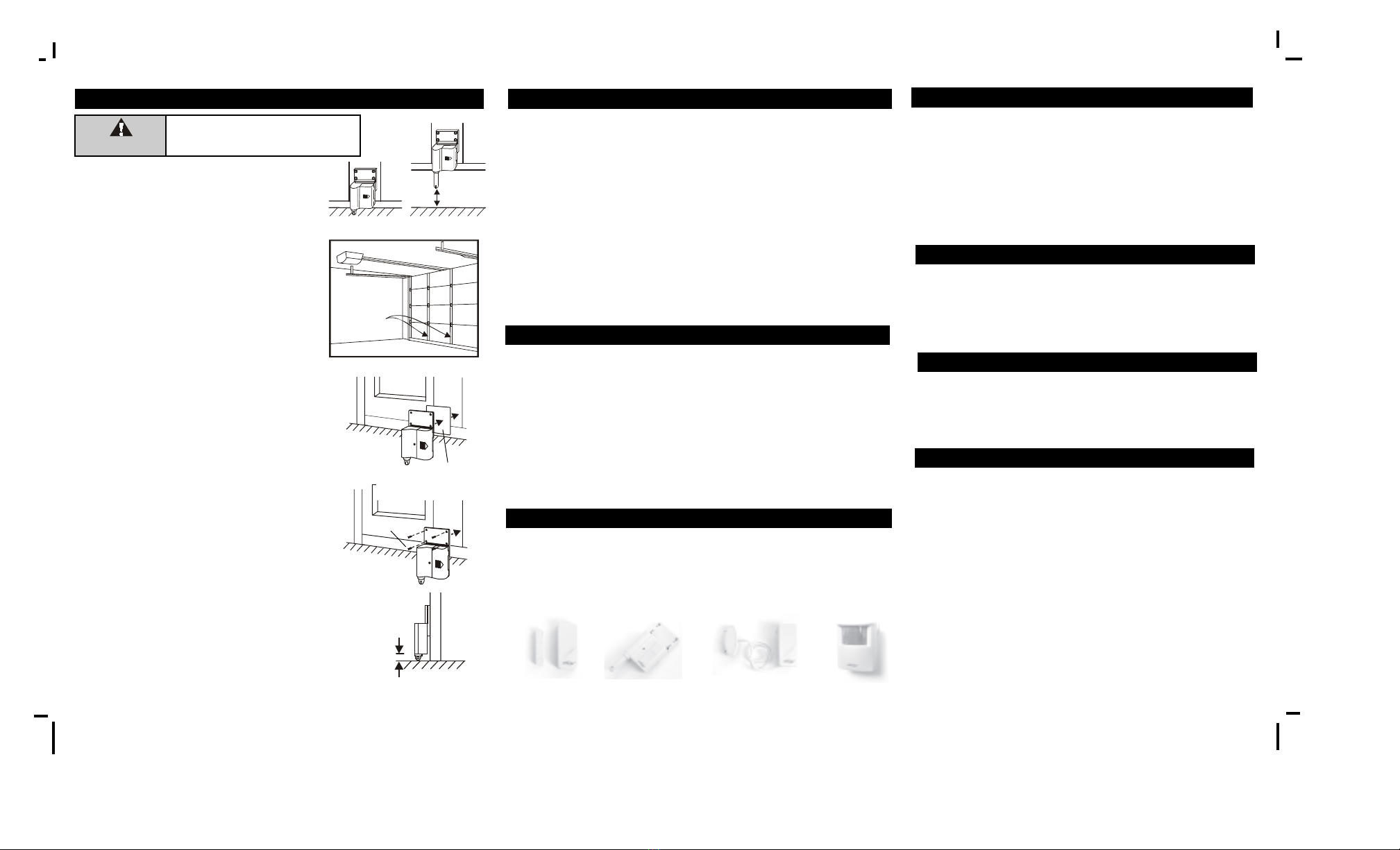
DiagramA
The Houselink®receiver can work with up to 4 different sensors: garage
door monitor sensors, door / window sensors, water sensors, indoor/
outdoor motion sensors, etc. Please visit www.skylinkhome.com or contact
us at [email protected] for more information of how to fully utilize
your Garage Door MonitorTM.
Step 1 – Select a spot on your garage door to
mount the sensor
Before you install the sensor onto the garage
door, make sure the garage door is closed.
The sensor assembly should be mounted on
one of the vertical supports of your garage
door near the bottom.
When the door is closed, the detection rod
should be retracted. When the door is open,
the detection rod will be extended.
One of
Vertical
Supports
Door closed Door open
Unplug the power cord of your garage
door opener before installation to ensure
power is not connected.
WARNING

Other SkyLink Accessories manuals

SkyLink WT-433 User manual

SkyLink

SkyLink WT-433 User manual

SkyLink WD-MT User manual

SkyLink

SkyLink WD-MT User manual

SkyLink HA-434TL User manual

SkyLink

SkyLink HA-434TL User manual

SkyLink GS-MT User manual

SkyLink

SkyLink GS-MT User manual

SkyLink HA-318T Guide User manual

SkyLink

SkyLink HA-318T Guide User manual

SkyLink WD-318T User manual

SkyLink

SkyLink WD-318T User manual

SkyLink WD-434T Manual

SkyLink

SkyLink WD-434T Manual

SkyLink Monitor GS-102 Guide User manual

SkyLink

SkyLink Monitor GS-102 Guide User manual

SkyLink TS-101A User manual

SkyLink

SkyLink TS-101A User manual

SkyLink PS-SD1-CH User manual

SkyLink

SkyLink PS-SD1-CH User manual

SkyLink PS-201 User manual

SkyLink

SkyLink PS-201 User manual

SkyLink HA-318T User manual

SkyLink

SkyLink HA-318T User manual

SkyLink PS-434A User manual

SkyLink

SkyLink PS-434A User manual

SkyLink PS-103 User manual

SkyLink

SkyLink PS-103 User manual

SkyLink Monitor GM-434TL Guide User manual

SkyLink

SkyLink Monitor GM-434TL Guide User manual

SkyLink WA-MT User manual

SkyLink

SkyLink WA-MT User manual

SkyLink FS-433 User manual

SkyLink

SkyLink FS-433 User manual

SkyLink ID-318 User manual

SkyLink

SkyLink ID-318 User manual

Popular Accessories manuals by other brands

Toto NEOREST 600 installation instructions

Toto

Toto NEOREST 600 installation instructions

Verano V610 Oslo installation manual

Verano

Verano V610 Oslo installation manual

Philips DLA91000H Specifications

Philips

Philips DLA91000H Specifications

Thuraya LM-P5 operating instructions

Thuraya

Thuraya LM-P5 operating instructions

SGB ELLIPSE 2 Series Hardware manual

SGB

SGB ELLIPSE 2 Series Hardware manual

VERTBAUDET 70303-0084 instruction manual

VERTBAUDET

VERTBAUDET 70303-0084 instruction manual

Intracom WiBASTM OSDR-HUB Installation

Intracom

Intracom WiBASTM OSDR-HUB Installation

Yamaha FW16E owner's manual

Yamaha

Yamaha FW16E owner's manual

Waterpik WP-500 Series manual

Waterpik

Waterpik WP-500 Series manual

Poweradd Pilot 4GS Pro user manual

Poweradd

Poweradd Pilot 4GS Pro user manual

DIAL PEC-A-5300-1M user manual

DIAL

DIAL PEC-A-5300-1M user manual

Sleepace Dot Quick setup guide

Sleepace

Sleepace Dot Quick setup guide

Roland DUO-CAPTURE EX owner's manual

Roland

Roland DUO-CAPTURE EX owner's manual

Clas Ohlson DB300 quick start guide

Clas Ohlson

Clas Ohlson DB300 quick start guide

Symbol CRD 2 00-1000S Series Quick reference guide

Symbol

Symbol CRD 2 00-1000S Series Quick reference guide

GE VE736AM installation instructions

GE

GE VE736AM installation instructions

Lord MicroStrain 3DM-CV5-15 user manual

Lord MicroStrain

Lord MicroStrain 3DM-CV5-15 user manual

SWEEX MM004PV3 manual

SWEEX

SWEEX MM004PV3 manual

manuals.online logo
manuals.online logoBrands
  • About & Mission
  • Contact us
  • Privacy Policy
  • Terms and Conditions

Copyright 2025 Manuals.Online. All Rights Reserved.