7
INSTALLERUSER
MAINTENANCE TECHNICIAN
1.4 HYDRAULIC CONNECTION.
Attention: before connecting the water heater and
so as not to make the warranty null and void on the
DHW heat exchanger, wash the system thoroughly
(piping, etc.) in a way to remove any residue that
could compromise the good functioning of the
water heater. Hydraulic connections must be made
in a rational way following the set-up of the water
heater couplings.
Attention: to preserve the duration of appliance
eciency features, in the presence of water whose
features can lead to the deposit of lime scale, installa-
tion of the polyphosphate dispenser is recommended.
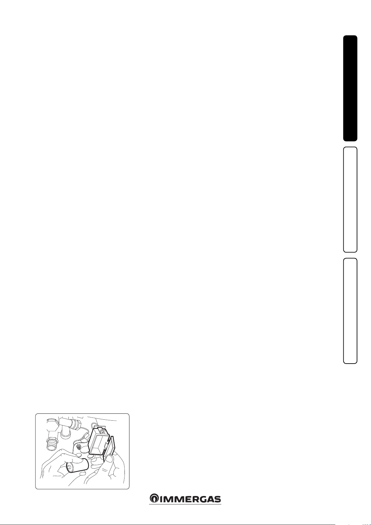
1.5 ELECTRIC POWER SUPPLY.
is water heater is powered by direct current via
one 1.5 V “LR 20” alkaline battery.
N.B.: The appliance is supplied by Immergas
with a battery in the packaging box and then not
connected.
In the ignition phase, it is therefore necessary to
connect it, setting it up in the correct position.
e battery is housed in a relevant compartment
organised in the lower le area, near to the hydraulic
couplings (Fig. 1-3).
Attention: water heater pipes must never be used
to earth the electric or telephone lines. Ensure that
this does not occur before the battery is inserted.
1.6 VENTILATION OF THE ROOMS.
In the room in which the water heater is installed
it is necessary that at least as much air ows as
that requested for by normal combustion of the
gas and ventilation of the room. Natural air ow
must take place directly through:
- permanent openings in the walls of the room
to be ventilated that lead towards the outside;
- ventilation pipes, individual or branched type.
e air used for ventilation must be withdrawn
directly from outside, in an area away from
sources of pollution. Natural air flow is also
allowed indirectly by air intake from adjoin-
ing rooms. For further information relating to
ventilation of the rooms follow that envisioned
in the current technical regulations.
Evacuation of foul air. In the rooms where the
gas appliances are installed it may also be neces-
sary, as well as the intake of combustion agent air,
to evacuate foul air, with consequent intake of a
further equal amount of clean air.
is must be realised respecting the provisions
of the technical regulations in force.
1.7 FLUE DUCTS.
egasapplianceswithattachmentfortheue gasdis-
charge pipe must have direct connection to chimneys
or safely ecient ues. e combustion products can
bedischargeddirectly outsideonlyif thesearemissing,
aslongas thecurrenttechnical regulationsfortheue
terminal are respected as well as the existing laws.
Connection to chimneys or ues. e connection
of the appliances to a chimney or ue takes place by
means of ue ducts.
In the event of ttings with pre-existing ues, these
must be perfectly clean because the detachment of any
wastefromthewallsduringfunctioning,couldblockthe
passage of ue gases, thus causing extremely dangerous
situations for the user.
e ue ducts must be connected to the chimney
or ue in the same room in which the appliance is
installed or, at most, in the adjoining room and must
complywiththe requirements indicatedbythecurrent
technical regulations.
1.8 FLUES/CHIMNEYS.
For the appliances with natural draught individual
chimneys and branched ues can be used.
Individual chimneys. e individual ues must be
dimensioned with respect to the standard in force.
Branched ues. In buildings with lots of oors,
branched ues can be used for the natural draught
evacuation of combustion products. New ues must
be designed following the calculation method and
provisions of the current technical regulations.
Chimney caps. e chimney cap is a device po-
sitioned on the top of an individual chimney or
branched collective ue. is device facilitates the
dispersion of combustion products, even in bad
weather conditions, and prevents the deposit of
foreign bodies.
is must meet the requirements of the current
technical regulations.
In order to prevent the formation of counter-
pressures that prevent the discharge of combustion
products into the atmosphere, the outlet height
corresponding to the top of the chimney/ue, inde-
pendently of any caps, must be out of the “respect
area”. It is therefore necessary to use the minimum
heights indicated in the gures stated in current
technical regulations.
Direct exhaust outside. e natural draught ap-
pliances to be connected to a chimney or a ue can
discharge the combustion products directly to the
outside, through a pipe passing through the perim-
eter walls of the building. In this case discharge takes
place through an ue duct, which is connected to a
draught terminal at the outside.
Positioning the draught terminals. e draught
terminals must:
- be installed on external perimeter walls of the
building;
- be positionedaccordingtothe minimumdistances
specied in current technical standards.
Combustion products exhaust of natural draught
or fan assisted appliances in open-top closed
environments. In spaces closed on all sides with
open tops (ventilation pits, courtyards etc.), direct
combustion product exhaust is allowed for natural
draught or fan assisted gas appliances with a heat
input rangefrom4to 35kW, providedthe conditions
as per the current technical standards are respected.
Important: it is prohibited to put the fumes exhaust
control device out of order voluntarily. Every piece
of this device must be replaced using original spare
parts ifthey have deteriorated. Inthecaseof repeated
interventions of the fumes exhaust control device,
check the ue exhaust pipe and the ventilation of the
room in which the water heater is located.
1.9 GAS SYSTEM STARTUP.
To start up the system, refer to the technical stand-
ards in force.
In particular, for new gas systems:
- open windows and doors;
- avoid presence of sparks or naked ames;
- bleed all air from the pipelines;
- check that the internal system is properly sealed
according to technical regulations in force.
1.10 APPLIANCE STARTUP IGNITION.
To commission the water heater (the operations listed
below must only be performed by a qualied rm and
without any unauthorised persons):
- check that the internal system is properly sealed ac-
cordingto thespecicationsset forth by regulations
in force;
- ensurethatthe typeofgasusedcorrespondstowater
heater settings;
- check that there are no external factors that may
cause the formation of fuel pockets;
- switch the appliance on and check correct ignition;
- make surethatthegasowrateandrelevantpressure
values comply with those given in the manual (see
par. 3.11);
- check the correct ventilation of the rooms;
- checkthe existingdraughtduringnormalfunction-
ing of the appliance, e.g. a draught gauge positioned
at the exit of the appliance combustion products;
- check that there is no backflow of combustion
products into the room, even during functioning
of fans;
- ensure that the chimney safety device intervenes in
the event of gas supply failure and check the relative
intervention time;
e water heater must not be started up even if only
one of the checks should be negative.
1.11 KITS AVAILABLE ON REQUEST.
• Water/gas connection cock kit (on request).
e gas cock is indispensable and must be type-
approved for the pre-xed use.
• Flexible pipes connection kit. ey can be used for
the DHW circuit connection.
e above-mentioned kits are supplied complete
with instructions for assembly and use.
Fig. 1-3


 null")
 null")


 Operation and maintenance instructions")