IMMI SMARTDOCK User manual
U.S. Patent No.
7,922,246
Patents Pending

2
Table of Contents
Page
General Information........................................................................................... 3
Warnings and Cautions..................................................................................... 4
Tools .................................................................................................................... 6
SmartDock Parts ................................................................................................ 6
Initial Set-Up and Adjustment .......................................................................... 7
Select Valve Retaining Tab .................................................................... 8
Install the Valve Retaining Tab.............................................................. 9
Raise SmartDock “Head”..................................................................... 10
Adjust “Wing”........................................................................................ 10
Open the SmartDock............................................................................. 11
Insert Cylinder into SmartDock........................................................... 11
Adjust Head Height ............................................................................... 12
Final “Wing” Adjustment...................................................................... 12
Installing the SmartDock into the Seat......................................................... 13
Normal Usage Adjustment ............................................................................. 14
Use .................................................................................................................. 15
Maintenance..................................................................................................... 16

3
SmartDock®Installation | User’s Guide
3
General Information
SmartDock is a hands-free self-contained breathing apparatus (SCBA) holder for re
apparatus. In the event of a collision, the top claws lock from inertial forces for a secure
hold.
The NFPA 1901 committee wants to ensure that SCBA bottles stored in the re apparatus
cab do not become projectiles during a crash. For this reason, the NFPA standard states that
“the bracket holding device and its mounting shall retain the SCBA unit when subjected to
a 9-G force.”
With traditional SCBA brackets, there are two things that must happen for the bottles to
remain in place:
1. The reghter must place the bottle in the bracket and latch it in place.
2. The bracket must be strong enough to hold the bottle.
The rst item is the responsibility of the reghter, and the second is the responsibility of
the bracket provider.
The unique feature of the SmartDock hands-free SCBA holder is that it removes the need
for the reghter to perform any extra latching, buckling or strapping action when placing
the bottle in the bracket.
Once installed per these instructions, the SmartDock is designed to meet NFPA 1901
requirements without any extra action by the reghter, other than properly placing the
bottle into the bracket.
The SmartDock uses inertia to keep the claws locked during deceleration. This inertial
action ensures that the SmartDock system will hold an SCBA bottle during an impact
caused by a crash.
Short of bolting the SCBA bottle to the structure of the cab, there is no way to guarantee
the bottle will always be retained if the crash is sufciently severe. The SmartDock bracket
has been tested to exceed NFPA 1901 requirements during a frontal crash. This capability
provides the optimum combination of convenience and strength, keeping the bottle retained
beyond NFPA requirements and eliminating the risk that a reghter will forget to engage
the strap or the latch. For these reasons, SmartDock provides the safest solution to in-cab
SCBA storage available today.

4
SmartDock®Installation | User’s Guide
Failure to follow these warnings may result in serious injury or death.
• Read all SmartDock Installation / User’s Guide instructions before installing or
using SmartDock.
• SmartDock is to be used for SCBA bottle and air pack storage only.
• Keep air pack harness loose when seated and belted. Bottle may not stay in holder
during a crash if the user has the harness strapped on tightly. Per NFPA Standard
1901, SCBA straps should be worn loosely when riding in the vehicle.
• Ensure proper t of SCBA in SmartDock claws.
• Ride only with SCBA installed in seat.
• Always wear seat belt – SCBA harness is not designed to hold reghter in a
crash.
• Use only with SCBA bottle and air pack weighing less than 35 lbs.
• Verify that the valve retainer brand ID matches the brand of the air pack you are
using. If they do not match, the pack may not be retained during a crash.
• Adjust to t before use
The SmartDock SCBA holder must be adjusted to t the SCBA bottle to be stored
in it. Do not store any air pack or bottle that does not meet the t criteria. Storing
any SCBA bottle and pack that does not t properly is dangerous as it may not be
retained during a crash.
• Claw Grip/Adjustment
The claws grip the bottle during a crash. The claw assembly must be adjusted
vertically so it grips the bottle where air pack harnesses, hoses or other
obstructions do not prevent the claws from closing properly. Do not store any
bottle and air pack if the claws cannot be adjusted to be clear of obstructions.
Never modify the SmartDock to adjust the claws
outside of the range provided.
• Air packs must be maintained in good condition and kept clean. Storing dirty, oily
or damaged bottles may affect the ability of the SmartDock to hold the bottle. The
SmartDock must be kept clean. Make sure the claws are kept clean and oil free. To
clean the SmartDock, use only warm water and mild detergent.
• Without inserting an air pack, check the claws periodically to make sure they
freely open and snap shut. This can be done by pulling the claws open by hand
and then shutting them again.
• Use only furnished SAE grade 5 fasteners to attach the SmartDock unit to seat
brackets.

5
SmartDock®Installation | User’s Guide
Standards Reference:
NFPA-1901, 2009 Edition, Standard for Automotive Fire Apparatus
NFPA-1852, 2009 Edition, Standard on Selection, Care, and Maintenance of Open-Circuit
Self-Contained Breathing Apparatus (SCBA)
Users must read and follow these instructions.
They are written to comply with NFPA guidelines.
Valve Retainer
During a crash, the air pack is held in place by the claws and valve retainer. The valve
retainer is the receptacle into which the valve must t (see drawing below). The shape of
the bottle valve is not the same for all air pack manufacturers, therefore the proper valve
retainer must be used. For ease of operation and safety, the correct valve retainer must be
properly matched to the SCBA valve being used. To facilitate matching of the correct valve
retainer to SCBA valve, the valve retainers have been marked for easy identication. Verify
that the valve retainer brand ID matches the brand of the air pack you are using
(if additional information is needed, see chart on pg. 9). If they do not match, the
pack may not be retained during a crash.
Failure to install, maintain and use SmartDock
in accordance with the instructions in this Installation
/User’s Guide and those provided by the Vehicle
Manufacturer can result in serious injury or death.
6
SmartDock®Installation | User’s Guide
Tool List
• 1/4 inch and 3/16 inch hex sockets and hex keys (Allen wrench)
• 9/16 inch socket
• 1/2 inch socket
• T45 Torx Plus socket or key
• Torque wrench capable of reading from 8 to 30 ft*lbs (100 to 360 in*lbs)
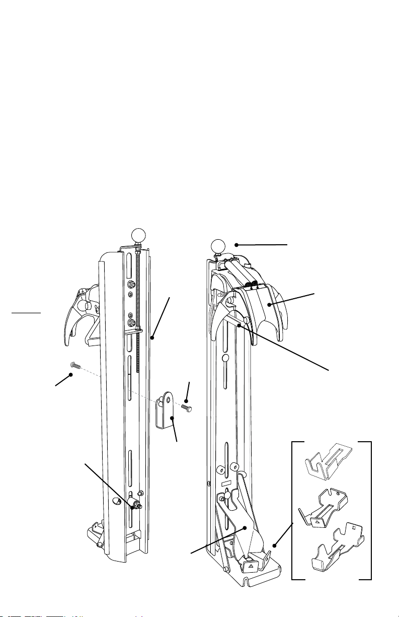
SmartDock Parts
Wing
Vertical
Support
Bracket
Guide
Plate
Claw
Assembly
Height
Adjustment
Knob
Mounting
Hardware
Included Valve
Retaining Tabs
5/16 – 18
Button Head
Screw
5/16 – 18
Hex Flange
Screw
Upper
Mounting
Bracket
PAGE 8 FIGURE 1 REV 2
7
SmartDock®Installation | User’s Guide
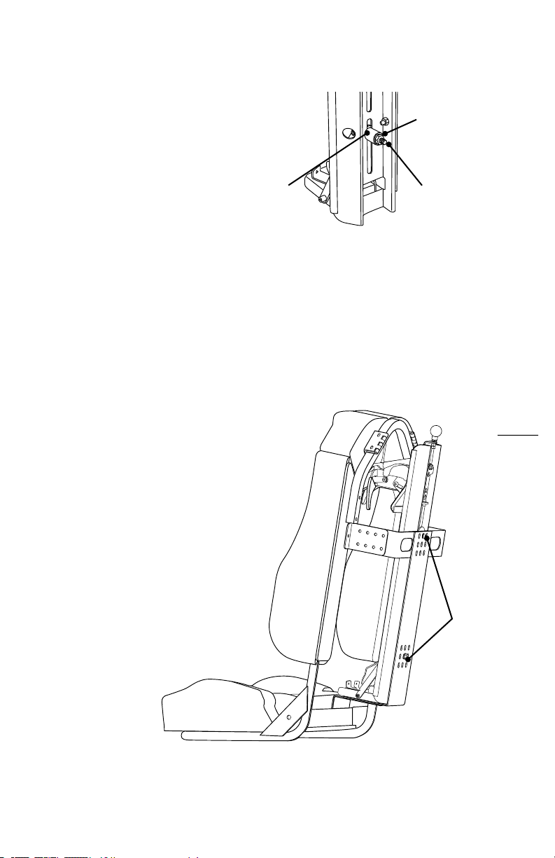
PAGE 7 FIGURE 2
Mounting Hardware and
Loose Parts
Verify parts list.
• (1) 5/16 – 18 bolt (pre-installed)
• (1) spacer (pre-installed)
• (1) 5/16 – 18 locking nut
• (1) additional valve retaining tab
• (1) 5/16 – 18 button head screw
• (1) 5/16 – 18 hex ange screw
• (1) upper mounting bracket
Locknut
Spacer Bolt
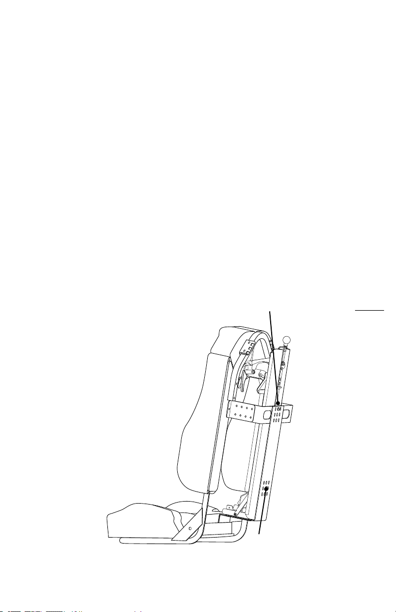
SmartDock Initial Set-Up
and Adjustment
Initial set-up and adjustments should be
performed with the SmartDock removed
from the SCBA seat, as access to some
adjustments will be difcult or impossible.
Remove the SmartDock from the seat by
removing the mounting nut and bolt from
the backside of the seat.
Make sure to note the mounting position
for easy re-installation.
Mounting
Bolt & Nut

8
SmartDock®Installation | User’s Guide
PAGE 8 FIGURE 1 REV 2
The SmartDock assembly has been pre-
congured to accommodate the Scott,
Draeger, Survivair and Sperian SCBA
valves. If this is the valve used in the
seat where the SmartDock system is to be
installed, refer to step 3 to verify that the
cylinder ts properly. If a different SCBA
valve will be used, the following instructions
explain how to congure the SmartDock for
each SCBA valve brand.
Step 1. Select Valve Retaining Tab
Each SmartDock assembly ships with three
reversible valve retaining tabs. These three tabs
give you ve options, accommodating virtually
every SCBA manufacturer on the market today.
If the wrong valve retainer tab is used, the air pack
may not be retained during a collision and could
result in serious injury or death.
Scott SCBA Valve
Note: Steps 1 - 2 should be followed before the
SmartDock assembly is installed in the seat.
Unmarked Tab
Square Tab
Triangle Tab
Circle Tab
U-Tab

9
SmartDock®Installation | User’s Guide
Step 2. Install the Valve Retaining Tab
a. Using the table above, identify the SCBA brand and
the corresponding valve retainer tab that you use.
b. Using the appropriate valve retaining tab,
mount it to the bottom plate using the
3/8-16 hex bolt and washer as shown.
Slide the tab as far forward as possible.
This position will work well with most
SCBA systems. Torque the hex bolt to
280 in*lbs (23 ft*lbs). The smaller hex
head bolt on the bottom plate works as
a key in the slot to provide fore and aft
alignment of the valve-retaining tab to
ensure proper t.
c. Reinstall the guide plate by aligning the
tab into the slot in the bottom plate.
Using a 3/16 inch hex key, install the
¼-20 socket head cap screw as shown
and torque to 100 in*lbs (8 ft*lbs).
If a tighter t is desired, repeat the
instructions in (b) and adjust the tab
rearward by small amounts until the
desired t is achieved.
PAGE 9 FIGURE 2_REV 2
Valve Retaining Tab
3/8 -16 Bolt
& Washer
1/4-20 Cap
Screw
Guide
Plate
10
MSA G1
Interspiro Scott
Draeger
Survivair
Sperian
ISI
MSA Tall
MSA Short
Square Triangle Circle Unmarked U-Tab
Valve Retainer Identication Mark

10
SmartDock®Installation | User’s Guide
PAGE 10 FIGURE 1
Height
Adjustment
Knob
Step 3. Raise SmartDock Head
Before installing the cylinder into the SmartDock
for the rst time, verify that the SmartDock head is
at least as high or slightly higher than the length
of the SCBA cylinder as measured from the bottom
of the valve to the rounded end of the cylinder. Use
caution when working with the SmartDock head to
avoid pinch points.
Note: Turning the height adjustment
knob clockwise raises the head and
counter-clockwise lowers the head.
Step 4. Adjust Wing
Using a T45 Torx Plus key, loosen the socket head
cap screws on both sides that hold the wing adjust-
ment and adjust the wing to its most rearward
position. It is only necessary to loosen the cap
screws about a 1/4 turn.
Wing
Cylinder Height + 1/4 Inch
Adjustment Direction
T45 Socket Cap Screw
11
SmartDock®Installation | User’s Guide
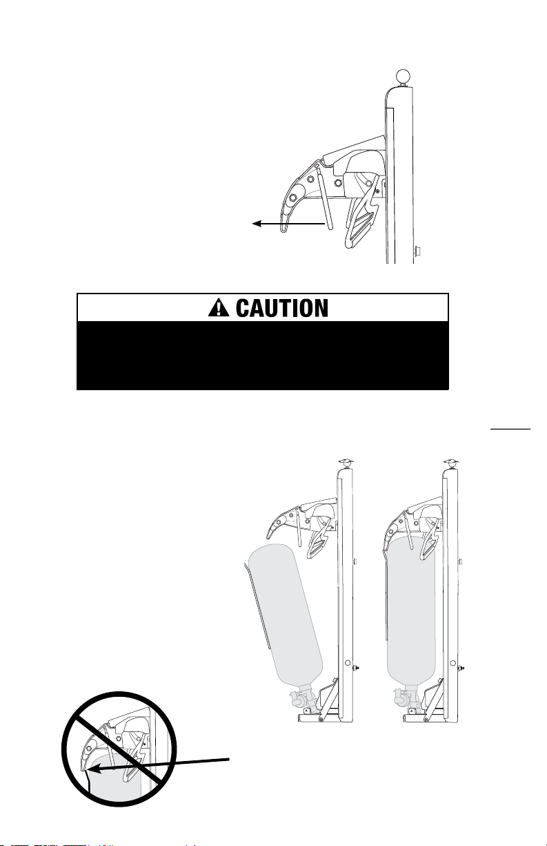
Step 5. Open the SmartDock
Grasp the yellow side of the “claw” on the Smart-
Dock head and pull it out while rotating it up. The
mechanism will be staged in its open position.
Verify that the strap is tightly secured around
the SCBA cylinder.
SmartDock claw assembly uses high spring force to open
and close. Use caution and avoid potential pinch points when
operating claw assembly manually.
Step 6. Insert Cylinder into
SmartDock
You are now ready to insert the SCBA
cylinder into the SmartDock and complete
the initial adjustment procedure.
a. Place SCBA cylinder valve into
SmartDock valve retaining tab.
b. Push the top of the SCBA cylinder
into the open SmartDock head,
which will automatically close
once inserted far enough.
Note: Insertion will become easier after
nal adjustments have been made.
Pull
Note: No part of the SCBA
pack (frame, hoses, etc.)
should be inside the claw.

12
SmartDock®Installation | User’s Guide
Step 7. Adjust Head Height
During normal operation, the SmartDock head should just
touch the top of the SCBA air cylinder. Adjust the head
height by turning the height adjustment knob counterclock-
wise to lower the head until the gap between the top of the
SCBA air cylinder and the bottom of the SmartDock head is
eliminated. The top of the SCBA air cylinder should be just
touching the bottom of the SmartDock head.
Step 8. Final “Wing” Adjustment
The SmartDock “wing” holds the SCBA
air cylinder in the proper orientation and
helps close the head when inserting the
SCBA air cylinder into the SmartDock.
Holding the SCBA air cylinder forward
against the two front claws, loosen the
two wing adjusting screws using a T45
Torx Plus key, swing the wing forward
until it touches the SCBA air cylinder,
and then tighten the wing adjusting
screws to 22 ft*lbs of torque.
The wing is not intended to be tight
against the SCBA air cylinder, and there
will be a small amount of play between
the SCBA air cylinder and the wing.
Gap
Height
Adjustment
Knob
Gap No Gap
Wing Adjusting
Screw
Wing
Air Cylinder
Forward
Swing Wing Forward
Against Air Cylinder
13
SmartDock®Installation | User’s Guide
Installing the SmartDock
Into the Seat
The SmartDock ships with pre-installed mounting bolts and spacers
for seat installation. The SmartDock uses the existing SCBA holder
mounting brackets that are supplied with SCBA compatible seats.
1. Place the SmartDock in the seat and check the
position of the pre-installed mounting bolts and
spacers. If the pre-installed bolts do not line up with
the existing mounting holes, the upper mount may be
loosened and shifted in the upper slot, and the lower
bolt and spacer can be relocated into either of the
lower mounting slots.
2. Align the mounting bolts with the desired holes
in the seat and secure them to the seat using the
supplied 5/16-18 locking nut for the lower mount and
the 5/16-18 hex ange screw for the upper mount.
Torque all fasteners to 20 ft*lbs. using a 1/2 inch
socket.
SmartDock can be mounted directly to the back
wall. This will require a wall mount kit (F104617),
which can be purchased from IMMI Customer
Service at 866.765.5835.
5/16-18 Hex Flange
Screw
5/16-18
Locking Nut

14
SmartDock®Installation | User’s Guide
Normal Usage Adjustment
During normal use, the SmartDock head must be raised or lowered to properly t the
SCBA and ensure the safe functioning of the system. This is due to small differences
in SCBA air cylinder length that can affect the t of individual SCBA air cylinders and
the SmartDock.
• If the head is too high, the SCBA air cylinder will seem loose in the SmartDock,
as the head will not be touching the top of the SCBA air cylinder. If severely
out of adjustment, the claw may seem like it stays open too long, and it may
be difcult to keep the pack, hoses and straps out during the insertion of the
SCBA.
• If the head is too low, the SCBA air cylinder will be difcult to insert and the
SmartDock head will require some force to completely close instead of draw-
ing the air cylinder in automatically. In some severe cases, the head may not
close at all.
To lower the SmartDock head, turn the height adjustment knob
counterclockwise as if you were trying to “unscrew” the knob.
To raise the SmartDock head, turn the height adjustment knob clockwise
as if you were trying to “tighten” the knob.
When tilting the cab for maintenance, it is recommended to remove SCBA packs from
the SmartDock.

15
SmartDock®Installation | User’s Guide
If you are unable to determine what type or size
of valve you have, do not use SmartDock. Using an
unapproved tank and/or valve could result in the
tank being released in a crash. Serious injury or
death could result. Contact 866.765.5835 if
you have questions regarding t and use of
SmartDock.
SmartDock Use
Use the following steps to safely ride in the seat when traveling to a re:
(Note: You should only ride with the SCBA installed in the seat.)
1. Wear bunker gear prior to entering the cab.
2. Enter cab safely using a three-points-of-contact method.
3. Wear air pack that is stored in the seat back.
4. Leave the SCBA pack harness loose until you exit the seat.
5. Buckle seat belt.
6. Indicate to driver that you are buckled safely in the seat.
7. Do not unbuckle seat belt until the vehicle has come to a stop, the parking brake is
engaged and the ofcer indicates it is safe to exit the cab.
8. Exit the seat by bending forward to release the SmartDock and then tighten the pack
harness straps.

16
SmartDock®Installation | User’s Guide
©2017 IMMI. All rights reserved. 08/17 3160P PN914672 Rev11
18881 IMMI Way | Westeld, IN 46074-3001 | 866.765.5835
imminet.com
Maintenance
The SmartDock needs to be kept clean. Make sure the claws are kept clean and oil
free. Check the claws periodically to make sure they freely open and snap shut. To
clean the SmartDock, use only warm water and mild detergent. Never lubricate.
Air packs must be maintained in good condition and kept clean. Storing dirty, oily or
damaged bottles may affect the ability of the SmartDock to hold the bottle. For proper
maintenance of air packs, refer to: NFPA 1852 Standard on Selection, Care and
Maintenance of Open-Circuit Self-Contained Breathing Apparatus (SCBA).
For additional information, visit
imminet.com/re-and-ems-vehicles/smartdock/.
BRINGING SAFETY TO PEOPLE
Other manuals for SMARTDOCK
2
Table of contents


