CLiC-iT PROTECTMAN RODEOSTOP B100 User manual


NOTICE D’UTILISATION
RODEOSTOP B100
SOMMAIRE
I. Informations générales
II. Utilisation prévue et applications
III. Limites d’utilisations
IV. Sauvetage
V. Modification de l’équipement
VI. Vérification de l’équipement avant son utilisation
VII. Installation du cordage
VIII. Caractéristique de l’équipement de protection individuelle qui requiert une
vérification par l’utilisateur avant de s’en servir
IX. Tout système doit être immédiatement retiré de la circulation si…
X. Exigences relatives au point d’ancrage
XI. Instructions relatives à la manière de se relier au point d’ancrage
XII. Instructions relatives au point d'accrochage correct à utiliser sur le harnais et
à la manière de s'y relier
XIII. Pour les systèmes d'arrêt des chutes
XIV. Instruction précisant qu'un harnais d'antichute doit être le seul dispositif de
protection du corps
XV. Avertissement précisant que dans un système d'arrêt de chute il faut vérifier
l'espace libre (Tirant d'air)
XVI. Information relative au danger susceptible d'affecter la performance de
l'équipement
XVII. Instructions sur la protection pendant le transport du matériel
XVIII. Informations relatives à la signification de tous les marquages, symboles sur
l'équipement
XIX. Lorsqu'il est requis qu'un examen de ce type soit effectué par un organisme
notifié
XX. Méthode de nettoyage, de désinfection et d'entretien
XXI. Recommandation concernant la fréquence des examens périodiques
Page
2
2
2
3
3
3
4
4
5
5
6
6
6
6
6
7
7
7
8
8
9

- 2 -
I. Informations générales
L’antichute RODEOSTOP B100 répond aux exigences de la directive européenne
89/686 CEE. Il estconforme à la norme EN 360 : 2002 A.R.A. Les tests ont été réalisés
avec une corde semi statique antipode de marque BEAL® (réf : CE EN 1891 type A
⌀10 mm, d’une résistance statique supérieure à 1500 DaN).
II. Utilisation prévue et applications
L’antichute RODEOSTOP doit avoir son point d’accrochage deux mètres au-dessus
d’une plateforme et doit être attaché avec des mousquetons à vis de type EN 362 de
résistance minimum supérieure à 1500 DaN. Tous les matériels (E.P.I.) utilisés en
complément doivent être référencés CE pour l’Europe. Tous les éléments doivent être
compatibles (bien lire la notice de chaque appareil).
Le RODEOSTOP B100 doit être utilisé avec :
-une corde semi statique antipode (réf : CE EN 1891 type A ⌀10 mm, d’une
résistance statique supérieure à 1500 DaN).
-un dispositif d’ancrage conforme à la norme CE EN 795
-un connecteur à vis conforme à la norme EN 362 reliant l’ancrage
RODEOSTOP B100.
-un connecteur à vis conforme à la norme EN 362 permettant la liaison du
support d’assurage au point d’accrochage dorsal, sternal ou ventral du harnais.
-un harnais d’antichute conforme EN 361 avec un point d’accrochage dorsal ou
sternal.
-aucune longe ne peut être ajoutée entre le connecteur à vis permettant la liaison
du support d’assurage au point d’accrochage du harnais.
III. Limites d’utilisations
L’antichute RODESTOP B100 doit être utilisé VERTICALEMENT.
Le mouvement pendulaire doit être limité à un maximum de 30° en prenant comme
repères le deuxième brin du cordage servant de fil à plomb.
Ne pas utiliser au-dessus ou à l’intérieur d’une cuve ayant des produits corrosifs.
Il est interdit de placer un câble métallique sur la poulie à l’intérieur du RODEOSTOP
B100.
Attention aux conditions médicales susceptibles d’affecter la sécurité de la personne
lors de l’utilisation normale de l’équipement. La personne doit être en bonne condition
physique pour résister à la surcharge provoquée par l’arrêt de la chute et pour pouvoir
attendre pendu dans son harnais les secours ou s’évacuer rapidement par elle-même.

- 3 -
L’équipement ne doit être utilisé que par une personne formée et compétente pour
l’utiliser en toute sécurité.
Il doit être utilisé par une seule personne de charge maximum de 130 kilos.
La personne doit lire ou se faire expliquer les instructions de la notice et s’y conformer.
Le non-respect de la notice peut présenter des risques de très graves blessures voire
un danger de mort.
IV. Sauvetage
Un plan de sauvetage doit être mis en place avant de commencer à travailler afin de
faire face à tous problèmes susceptibles de survenir pendant le travail. Une autre
personne sur place doit prévenir les secours en cas d’urgence.
Si les secours tardent à venir, le RODEOSTOP B100 permet à l’utilisateur de
s’évacuer tout seul avec un huit de montagne tout doucement à la descente, avec
arrêt, départ à volonté ou d’être évacué en toute sécurité de la même manière par une
autre personne positionnée au sol.
V. Modification de l’équipement
Le RODEOSTOP B100 ne peut en aucun cas être modifié ou ouvert.
Toute réparation de l’appareil par des personnes non agrée par le fabricant est
interdite.
Toutes les réparations doivent être effectuées dans un centre agrée par le fabriquant
ou par lui-même sur devis ou sur prix forfaitaire pour les pièces à changer.
Tout manquement à ces règles résultera à une non garantie de l’appareil par le
fabricant.
VI. Vérification de l’équipement avant son utilisation
Avant toute utilisation du RODEOSTOP B100, vérifier que le point d’ancrage soit bien
placé à la verticale au-dessus du plan de travail et qu’il résiste à une charge de 1500
DaN.
Vérifier que l’ensemble de l’appareil est en parfait état et que toutes les vis
d’assemblages sont présentes et bien fixées.
VII. Installation du cordage
- 4 -
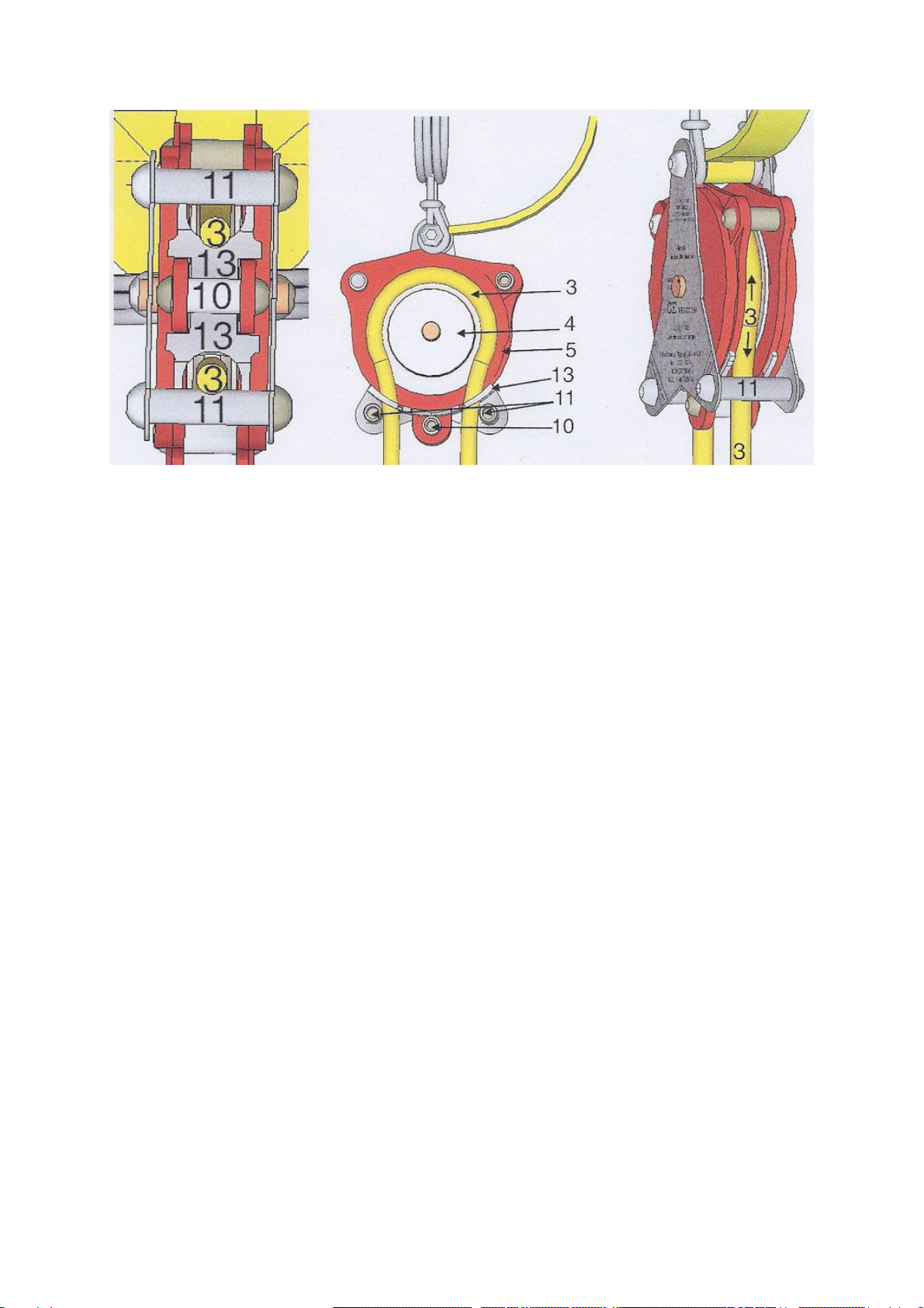
L’installation du cordage dans le RODEOSTOP B100 est simple.
Sous l’appareil introduire la corde (3) entre la pièce de pincement (13) et l’entretoise
(11).
Faire suivre la corde (3), en l’appuyant dans le fond de la gorge de la poulie etressortir
la corde (3) de l’autre côté entre la pièce de pincement (13) et l’entretoise (11). Voir le
croquis ci-dessus.
Il faut veiller à ce que la corde (3) soit bien passée en appuie dans le fond de la gorge
de la poulie (4) jusqu’à la sortie de cette corde (3) de l’autre côté entre la pièce de
pincement (13) et l’entretoise (11) du bas de l’appareil.
Vérifier à nouveau que la corde (3) de sauvetage est correctement installée dans
l’appareil, en la tirant doucement dans les deux sens. Elle doit circuler librement dans
la poulie folle. Puis tirer d’un coup sec, il doit se produire un arrêt net avec un blocage
du cordage. Faites de même avec l’autre brin, un arrêt net avec blocage doit se
produire également.
La manière d’utiliser le RODEOSTOP B100 ne dispense pas les utilisateurs de se
conformer aux normes en vigueur régissant chacune des activités concernées.
VIII. Caractéristiques de l'équipement de protection individuelle qui
requiert une vérification par l'utilisateur avant de s'en servir
Bien lire tous les paragraphes de cette notice, notamment les paragraphes XII, XV et
XVI avant d'utiliser l'ensemble de l'E.P.I., puis prendre le temps de bien contrôler tout
l'équipement.
Sur le harnais d'antichute, il faut examiner les sangles, les fils des coutures, l'état des
boucles, la corrosion, les déformations et les salissures.

- 5 -
Vérifier l'état de l'élingue, acier ou sangle ; vérifier sur l'antichute les traces de coups,
les fissures, le bon état du marquage.
Vérifier que toutes les vis d'assemblages de l'appareil sont présentes et bien fixées.
Accrocher l'appareil à hauteur d'homme et faire circuler le cordage sur toute sa
longueur pour en contrôler le bon état, déceler s'il y a des traces de brûlures, d'huiles,
d'abrasion, de coupures et vérifier qu'il n'y a pas de nœuds parasites en formation sur
tout le parcours de la corde.
Contrôler à nouveau le fonctionnement du blocage du cordage.
Pour être plus en sécurité, n'utiliser que des mousquetons à vis, conforme à la norme
EN 362.
IX. Tout système doit être immédiatement retiré de la circulation :
- si la sécurité est mise en doute.
- lors d'un contrôle ou pour une autre raison, si l'E.P.I. présente des signes
d'endommagement par voie de choc ou autres motifs de disfonctionnement, il est
impératif de mettre immédiatement l'appareil hors service, de lui mettre une étiquette
portant la mention inutilisable et de le retourner à un centre agrée par le fabricant ou
au fabricant pour une remise en état.
- s'il a été utilisé pour arrêter une chute, le sortir du circuit et contrôler à nouveau
l'appareil par une personne compétente.
X. Exigences relatives au point d'ancrage
Ne jamais travailler au-dessus de l'antichute placé sous le point d'ancrage.
L'antichute doit être placé à la verticale au minimum à deux mètres au-dessus du plan
de travail de la personne attachée par le pontet dorsal ou sternal de son harnais.
Choisir de préférence un point d'ancrage réservé à cet usage, ou qui présente une
résistance minimum de 1500 daN, en cas de doute le faire contrôler par un organisme
agrée.
Le point d'ancrage doit être complètement dégagé de tout obstacle pour ne pas nuire
au bon fonctionnement de l'antichute.
Le choix de l'emplacement et de la fixation du point d'ancrage est de la responsabilité
du chef de chantier, ou d'une entreprise spécialisée.
XI. Instructions relatives à la manière de se relier au point d'ancrage
Installer le point d'ancrage comme expliqué au paragraphe X.

- 6 -
Relier l'antichute au point d'ancrage avec un mousqueton de la norme EN 362, ou
avec une élingue norme CE ou en sangle ou câble acier d'une résistance de 2000 Kg
minimum.
XII. Instructions relatives au point d'accrochage correct à utiliser sur
le harnais et à la manière de s'y relier
Veillez à toujours se relier au circuit de sécurité du RODEOSTOP B100 par le pontet
dorsal, sternal du harnais d'antichute.
Utiliser une boucle à huit si nécessaire.
Attention il est interdit de placer une rallonge entre la boucle à huit du cordage
d'assurage et le pontet dorsal, sternal du harnais. Seul le mousqueton de liaison de la
norme EN 362 est prévu pour cela.
XIII. Pour les systèmes d'arrêt des chutes
Il est essentiel que quand la personne monte, elle doit faire attention que la corde
d'assurage n'accumule pas de mou.
Si l'installation est correcte, cela ne devrait pas se produire.
Au cas où cela se produirait, rétablir la tension du cordage en changeant les réglages
du circuit, en redescendant un peu ou en tirant légèrement sur le cordage d'assurage.
XIV. Instruction précisant qu'un harnais d'antichute doit être le seul
dispositif de protection du corps
Partout où il y a risque de chute, il faut utiliser un harnais d'antichute équipé d'un pontet
dorsal, sternal et, possédant une fessière confortable et réglable.
XV. Avertissement précisant que dans un système d'arrêt de chute il
faut vérifier l'espace libre (Tirant d'air)
Attention, chaque fois qu'il y a un risque de chute, il est important de vérifier qu'il n'y a
pas d'obstacle saillant sous la personne qui utilise un antichute.
Ilfaut prévoir un espace de vide assez important.Le tirantd'air ne doit pas être inférieur
à la hauteur de la personne plus 1,35 mètre pour un cordage tendu, vertical et
rectiligne.
Le tirant d'air = hauteur de la distance d'arrêt des chutes.
XVI. Information relative au danger susceptible d'affecter la
performance de l'équipement
S'assurer que toutes les cordes et sangles soient protégés contre les dommages dû
au frottement ou aux coupures qui pourraient être provoqués par des surfaces
abrasives ou des angles coupants, coupures de cutter ou autres, arêtes vives, agents

- 7 -
chimiques, sources de chaleur, grain de soudure, poussières, sable, ciment dans
l'appareil.
Interdiction de décrocher une personne en coupant la corde avec un cutter.
XVII. Instructions sur la protection pendant le transport du matériel
Il est très important que le RODEOSTOP B100 soit protégé pendant tous les
transports. Le reste de l'E.P.I. à savoir (cordages, harnais, mousquetons) doit être
transportés bien rangés dans un coffre ou un sac approprié, à l'abri des chocs et
rangés à sa place habituelle au retour du chantier.
Tout transport en vrac dans le sable, poussière du plancher d'un véhicule risque de
rendre inutilisable à court terme l'antichute, les cordages et le harnais.
XVIII. Informations relatives à la signification de tous les marquages,
symboles sur l'équipement
Le marquage est réalisé par procédé laser sur la chape inox de l'antichute
ROSDEOSTOP B100.
SUR LA FACE AVANT EST GRAVE :
•un cadran des douze mois qui indique le mois de fabrication.
•deux demi cadrans des années qui indiquent l'année de la fabrication et de la
révision.
•un pictogramme représente un livre avec une bougie (lire la notice d'utilisation).
•un pictogramme représente un poids maximum de 130 Kg.
•conforme à la norme européenne CE0082-EN 360 : 2002.
•CE0082 0082, numéro d'identification de l'APAVE SUDEUROPE, organisme
notifié en charge du contrôle de production et ayant réalisé l'examen CE de
type.
•l'inscription : antichute automatique.
•le nom et la marque commerciale : RODEOSTOP B100.
•le numéros de lot : exemple : lot 0101 N° série 0001.
•un moyen d'identification : nom du fabricant et coordonnées PROTECTMAN
•Tel.: (33) 0145345205 Fax: (33) 0954178012 www.rodeostop.com.
•un pointillé oblique traçant le cordage de chaque cotés sous la chape inox
marqué "⌀10 mm" et "Rope semi statique CE EN 1891 A".
INFORMATION DE MARQUAGE POINÇONNAGE :
Un marquage par poinçonnage sera effectué. Ce sera le poinçonnage des mois et des
années, effectuées directement sur la chape inox, quand la pièce est démontée lors
de sa révision obligatoire des douze mois.
SUR LA FACE ARRIERE EST GRAVE :

- 8 -
•Figure 1 : Utilisation de l'antichute B100 en position verticale avec un cordage
tendu par un contrepoids ;
•Figure 2 : Utilisation de l'antichute B100 en position verticale circuit fermé
alternatif "va-et-vient" avec un cordage tendu par un contrepoids ;
•un pointillé sur chaque côté représente le passage du cordage sous la chape
inox marqué "⌀10 mm" et "Rope semi statique CE EN 1891 A".
XIX. Lorsqu'il est requis qu'un examen de ce type soit effectué par un
organisme notifié
APAVE SUDEUROPE SAS
17, boulevard Paul Langevin
38600 Fontaine
France
CONTACTER LE SIÈGE DU FABRICANT DU RODEOSTOP B100 :
Protectman
2 Rue Maisant
92190 MEUDON
France
Tel : 00 331 4534 5205
Fax : 00 339 5417 8012
Email: rodeostop@gmail.com
XX. Méthode de nettoyage, de désinfection et d'entretien
Les E.P.I. ayant été utilisés dans certains lieux contaminés doivent être décontaminés
ou détruits sur place par les services spéciaux. Ne plus les transporter ni les utiliser
avant toute décontamination.
Il est formellement interdit d'utiliser de l'air comprimé ou de l'eau pour le nettoyage de
l'antichute. Le nettoyage de l'antichute doit être effectué seulement avec une éponge
humide, à la rigueur quelques gouttes de liquide vaisselle ou savon. Rincer et essuyer
avec un chiffon humide. Si l'eau rentre dans l'appareil il suffit de pendre l'appareil pour
éviter que l'eau ne stagne à l'intérieur. Il est important d'utiliser le matériel propre et en
bon état. Pour cela il est nécessaire de se conformer strictement à ces méthodes.
SECHER L'EQUIPEMENT MOUILLE :
Si l'E.P.I. est mouillé laissez le sécher naturellement à l'écart de toutes sources de
chaleurs directes.
CONDITION DE STOCKAGE :

- 9 -
Le matériel doit être stocké dans un endroit sec et propre loin des sources de chaleurs
et d'humidité.
Les E.P.I craignent les déformations, les vibrations ou les u.v. Les E.P.I.sales peuvent
être attaqués par la vermine et les rongeurs, l'antichute sera suspendu par son
mousqueton, ne pas entreposer les E.P.I. sur le sol.
METHODE D'ENTRETIEN ADAPTE - LUBRIFICATION :
L'antichute RODEOSTOP B100 demande très peu d'entretien.
Le maintenir propre est son gage de longue vie.
Ne jamais huiler ni graisser RODEOSTOP B100.
Ne jamais démonter RODEOSTOP B100.
Pour des raisons de sécurité, tous les travaux de remise en état (réparation) doivent
être faits à l'usine ou par un réparateur agrée, sur forfait ou sur devis pour les pièces
à changer.
DUREE DE VIE :
La durée de vie du produit est difficile à prévoir, elle dépend de l'utilisation et de
l'entretien de l'équipement.
Elle est de 5 ans pour une utilisation normale, et de 2 ans pour une utilisation intensive,
cette durée de vie pourra être reconduite à l'issue des résultats du contrôle périodique.
XXI. Recommandation concernant la fréquence des examens
périodiques
Le RODEOSTOP B100 à rappel automatique doit être retourné tous les douze mois à
l'usine ou dans un centre agrée pour un contrôle annuel obligatoire. Le RODEOSTOP
de plus de 5 ans d'âge nécessite d'une remise en service (échange standard) dans
nos ateliers.
Date du prochain contrôle : voir sur la fiche de révision ou douze mois après la date
d'achat.
RODEOSTOP®-B100 répond aux exigences de la directive européenne
89/686/CEE et est conforme à la norme EN 360 : 2002 A.R.A.
- Protectman France 2014 -

INSTRUCTIONS FOR USE
RODEOSTOP B100
SUMMARY
Page
I. General information
II. Anticipated use and application
III. Limits to use
IV. Rescue
V. Modification of the equipment
VI. Checking the equipment before use
VII. Installing the rope
VIII. Characteristics of personal safety equipment which require checking before use
IX. The complete device must be immediately withdrawn from circulation if…
X. Anchorage point requirements
XI. Instructions for linking up to the anchorage point
XII. Instructions for linking the anchorage point to the harness
XIII. For fall arrest systems it is essential that…
XIV. A fall arrest device is the only apparatus…
XV. Warning : Check the area where the RODEOSTOP B100 is to be used
XVI. The potential danger affecting the performance of the equipment
XVII. Protection when transporting the material
XVIII. The simplification of symbols & marking on the equipment
XIX. Contacting the head office of PROTECTMAN the manufacturer of the equipment
XX. For the security and information of the non-France-based purchasers of the
RODEOSTOP B100
XXI. Cleaning and disinfecting the RODEOSTOP B100
XXII. The periodic check-up
2
2
2
3
3
3
4
5
5
5
5
5
6
6
6
6
7
7
7
8
8
9

- 2 -
I. GENERAL INFORMATION AND DISCRIPTION
The fall arrest device RODEOSTOP B100 meets and complies with all the
requirements of the European directives 89/686 CEE. It conforms to standards
CE0082 –EN360: 2002 A.R.A. Tests have been carried out with semi-static antipode
rope BEAL (ref: CE1891 type A Ø10/10.5 mm with static resistance more than 1500
DaN)
II. ANTICIPATED USE AND APPLICATION
The fall arrest device RODEOSTOP B100 must have its anchorage point two meters
above a platform and must be attached with connectors CE EN362 with a minimum
resistance more than Rr 1500 DaN. All the complementary components used must
be European CE recognized, CE referenced and be compatible with each other.
(Read carefully the operating instructions for each item).
The RODEOSTOP B100 must be used with:
A. An anchorage point complying with European standard CE EN 795.
B. A connector complying with European standard CE EN 362 linking the anchorage
point to RODEOSTOP B100.
C. A connector complying with European standard CE EN 362 links the
RODEOSTOP B100 to the harness.
D. A fall arrest device harness complying with European standard CE EN 361
equipped with dorsal, sternum and ventral attachment points.
E. Nothing is to be added or come between the connector linking the RODEOSTOP
B100 to the harness.
III. RESTRICTIONS OF USE OF THE RODEOSTOP B100
The angle of the pendulum movement must not exceed 30 degrees.
Do not use above or inside a tank or cistern containing corrosive products.
Never put a metallic cable on the pulley inside the RODEOSTOP B100.
Great care must be taken to ensure that everyone using the fall arrest device is in
good physical health. An unforeseen emergency such as an arrest of the
RODEOSTOP B100 can make heavy demands on the user, so it is essential to be fit
to cope successfully with such situations.
The device is to be used only by a competent and trained person.
The RODEOSTOP B100 should only be used by one person at a time who does not
exceed 130 kilos in weight.

- 3 -
The person must read or have explained to him/her the instructions. Disregard of the
instructions can lead to very serious risks and injury and even to death.
IV. RESCUE
Safety procedures must be set up well in advance of use so that any problem arising
later can be dealt with quickly and effectively. Another person must also be present
to get help in an emergency.
If the help is slow in coming the RODEOSTOP B100 enables the user to lower
himself down alone gently with a “8” descender (“8” shaped buckle) controlling his
own movements such as stopping and starting.
Alternatively, someone on the ground can evacuate the user in difficulty in the same
way and in complete safety.
V. MODIFICATION OF THE EQUIPMENT
Under no circumstances should the RODEOSTOP B100 be modified or opened up.
Repairs can only be effected by people authorized by the manufacturer.
All repairs must be done by the manufacturer on the basis of an estimate or an all-
inclusive price for the parts or in a workshop authorized by the manufacturer.
Any departure from these restrictions will invalidate the manufacturer’s guarantee.
VI. CHECKING THE EQUIPMENT BEFORE USE
Before use check that the anchorage point is completely vertical above the work
place and that it can accept a charge of 1500 DaN.
Check that everything on the RODEOSTOP B100 is in a perfect state and that all
screws are tightly fixed.
VII. INSTALLING THE ROPE
Rope installation in the RODEOSTOP B100 is easy.
At the bottom of the device introduce the rope (3) in the U of the groove (13) inside
the brace (11). Pull the rope (3) through by pushing it into the center of the pulley and
bringing the rope out again (3) on the other side in the U slot inside the brace (11).
See sketch below.

- 4 -
Bottom view internal view side view
Make sure that the rope (3) has passed all-round the center of the pulley (4) until it
comes out on the other side in the U groove (13) between the two braces (11) at the
bottom of the apparatus.
Check again that the safety rope (3) is correctly installed in the apparatus by gently
pulling it in both directions. The rope should circulate freely on the pulley. Then give
the rope a sharp pull. This should stop the rope and block it. Do the same with the
other side. This should produce the same results by stopping and blocking the rope.
VIII. CHARACTERISTICS OF PERSONAL SAFETY
Equipment that require checking before use.
Carefully read everything, but particularly sections VII, XV and XVI of the instructions
for Use of the RODEOSTOP B100 before use, then take time to check all the
equipment.
Harness: check the straps, the stitching of the seams, the state of the buckles and
the signs of corrosion and warping. Also, the general cleanliness and freedom from
dirt.
Sling: check the condition steel or strap, signs of cracking, the good state of the
markings and traces of knocks.
Check that all fixtures are tight and in good condition.
Hold up the apparatus and check that the full length of the rope is in good working
order with no traces of burning, oil, wear and tear, cuts and no sign of parasitic
knots.

- 5 -
Also, check again to ensure the rope functions properly and stops and blocks
correctly.
To be totally safe only use connectors European reference: EN 362.
IX. THE APPARATUS MUST BE IMMEDIATELY WITHDRAWN FROM
CIRCULATION IF……
…..there are doubts about the safety system.
…..when during a check-up or for any other reason the fall arrest device shows signs
of damage through a knock or other cause of malfunction, it is imperative to put the
apparatus out of service and attach a label to that effect. Then the apparatus should
be sent to a center authorized by a manufacture for repair.
…..it has been used for arresting a fall, remove from use and get a competent person
to give another check-up.
X. ANCHORAGE POINT REQUIREMENTS
Never work above the fall arrest device or under an anchorage point.
The fall arrest device must be placed vertically at least two meters above the work
place of the person attached by the dorsal, sternum, or ventral attachment on his
harness.
The anchorage point must be completely clear of any obstacle which could
jeopardize the smooth functioning of the fall arrest device.
The choice and fixing of the anchorage point is the responsibility of the site manager
or specialized firm.
XI. INSTRUCTIONS FOR LINKING UP TO THE ANCHORAGE POINT
Install the anchorage point as explained in section X.
Link up the fall arrest device to the anchorage point with a connector complying with
European standard EN 362 or with a sling or strap complying with European
standards or alternatively with steel cable capable of withstanding a minimum charge
of 2000 kilos.
XII. INSTRUCTIONS FOR LINKING UP THE ANCHORAGE POINT TO THE
HARNESS
Always be careful to link up the RODEOSTOP B100 safety system by means of the
dorsal, sternum or ventral connector on the harness.

- 6 -
Use an “8” shaped buckle if necessary.
Never put an extension or whatever between the “8” shaped buckle of the safety rope
and the dorsal, sternum or ventral attachments on the harness. Only the connector of
European standard EN 362 is designed for that.
XIII. FOR THE FALL ARREST SYSTEM IT IS ESSENTIAL THAT…...
.…..the person going up should take great care that the safety rope does not build up
any slack.
That should never happen if the installation has been properly done: the rope should
always be taut.
However if the safety rope does become slack then rope tension can be re-
established by lowering the apparatus and going down a little or by giving the safety
rope a gentle pull –or two.
XIV. A FALL ARREST DEVICE IS THE ONLY APPARATUS.…..
…..wherever there is a risk of a fall it is essential to use a fall arrest harness
equipped with dorsal, sternum and ventral connectors fitted above the waist with a
comfortable and adjustable seat.
XV. WARNING: CHECK THE AREA WHERE THE RODEOSTOP B100 IS TO BE
USED
Wherever there is a risk of a fall it is important to ensure there are no obstacles or
obstructions under the person using the fall arrest device.
A large open space is essential for such activity. There must be an area of at least
the height of the person plus another 1.35 metres for a taut, vertical and rectilinear
rope system.
XVI. THE POTENTIAL DANGERS AFFECTING THE PERFORMANCE OF THE
EQUIPMENT
Make quite sure that the ropes and straps are protected from danger caused by
rubbing, scraping and friction caused by abrasive and sharp edged surfaces, acute
pointed angles, cuts from Stanley Knifes; chemical products, heat; bits of soldering or
welding, dust, sand, cement getting inside the apparatus.
Do not release a person from the device by cutting the rope with a Stanley Knife.

- 7 -
XVII. PROTECTION WHILE TRANSPORTING THE MATERIAL
It is very important to protect the RODEOSTOP B100 during transport to avoid
damage. All the parts of the fall arrest system (ropes, harness, connectors) should be
carefully placed in a suitable container and sheltered from knocks and rubbing into
each other. On return to the site the RODEOSTOP B100 should be stored away
carefully.
There is a real risk that the ropes, harness and fall arrest device scattered higgledy –
piggledy on the dusty, sandy floor of a vehicle will quickly become unusable if taken
to the site in such a way.
XVIII. THE SIGNIFICANCE OF SYMBOLS AND MARKINGS ON THE EQUIPMENT
The laser-engraved markings on the stainless-steel casing of the RODEOSTOP
B100 carry important information.
➢a dial of twelve months
➢a semicircle dial of years
➢a book (read the instructions for use)
➢a pictogram representing a maximum weight of 130 kg
➢the European standard reference CE0082-EN360: 2002 A.R.A.
➢the inscription: automatic full arrest device, the name and trade mark –Rodeostop
B100
➢the lot number –for example lot 0101 serial number 0001
➢a means of identification: manufacturer’s name and address: PROTECTMAN tel.
(33) 0145345205 fax: (33) 0954178012 www.rodeostop.com
➢an oblique dotted line showing ropes on each side under stainless steel casing
engraved 10/10.5mm semi-static CE EN 1891A
INFORMATION ON THE DIE-STAMPING:
Marking by die-stamping will be effected as and when appropriate. This will be the
die-stamping of the months and years directly onto the stainless-steel casing during
the dismantling necessitated by the obligatory annual check-up.
XIX. CONTACTING THE HEAD OFFICE OF THE MANUFACTURER OF
RODEOSTOP B100
Protectman
2 Rue Maisant
92190 MEUDON
FRANCE
Tel: 00 331 4534 5205

- 8 -
Fax: 00 339 5417 8012
Email: rodeostop@gmail.com
XX. FOR THE SECURITY AND INFORMATION OF NON-FRANCE-BASED
PURCHASERS OF THE RODEOSTOP B100
If the fall arrest device is sold in a country other than France, then it is obligatory to
provide and include the following with the apparatus:
The instructions for use, for maintenance, periodic check-ups and repair in the
language of the country.
In accordance with European legislation operating instructions for the RODEOSTOP
B100 which is originally for exclusive distribution in France must be translated into
the principal languages later.
XXI. CLEANING AND DISINFECTING THE RODEOSTOP B100
Fall arrest devices that have been used in contaminated places must be
decontaminated on the spot by the appropriate specialized services. Do not move or
use before proper decontamination has been carried out.
It is categorically forbidden to use compressed air or water to clean the fall arrest
device. Cleaning should only be done with a damp sponge or if absolutely necessary
a few drops of washing-up liquid or soap may be added. Rinse and dry with a moist
cloth. If water does get into the apparatus hang it up to prevent the water from
stagnating inside. It is important to be able to use a device which is clean and in good
condition, so to do that these cleaning methods must be strictly adhered to.
DRYING WET EQUIPMENT:
If the fall arrest device has got wet, then dry it out naturally away from direct heat.
STORING CONDITIONS:
The material must be stored in a dry and clean place well away from all sources of
heat and humidity. Fall arrest devices must not be subject to vibrations or sunlight to
avoid warping.
The storage place used for the apparatus must be free therefore from vibrations and
sunlight. Dirty fall arrest devices attract vermin and rodents, so hang the
RODEOSTOP B100 on a hook and do not put on the ground.
MAINTENANCE AND LUBRICATION:
The RODEOSTOP B100 requires very little maintenance.
Keeping it clean is a guarantee for a long life for the apparatus.

- 9 -
Never oil or grease the RODEOSTOP B100
Never dismantle the RODEOSTOP B100
For security reasons, all repairs must be done at the factory or by an authorized
repairer for a fixed price quotation for the parts changed.
LIFETIME:
The lifetime of the product is difficult to predict; it depends on the use and
maintenance of equipment.
She is 5 years for normal use, and 2 years for heavy use, this life may be renewed at
the end of the results of periodic inspection.
XXII. THE PERIODIC CHECK-UP
The automatic return RODEOSTOP B100 must be sent back to the factory or an
authorized center every twelve months for a check-up and renewal date of next
check-up: see the check-up sheet or twelve months after the purchase date.
- Protectman France 2014 -

BEDIENUNGSANLEITUNG
RODEOSTOP B100
INHALT
Inhalt Seite
I. allgemeine Informationen 3
II. Anwendung 3
III. Nutzungseinschränkungen 3
IV. Rettung 4
V. Änderungen der Ausrüstung 4
VI. Überprüfen der Ausrüstung vor dem Einsatz 4
VII. Einlegen des Seiles 5
VIII. Merkmale der PSA, die vor dem Gebrauch überprüft werden müssen 6
IX. Ablegereife 6
X. Anforderung der Ankerpunkte 6
XI. Anleitung für den Anschlag am Ankerpunkt 7
XII. Anleitung für die Verbindung von Gurt und Sicherungssystem 7
XIII. Wichtige Hinweise für Höhensicherungsgeräte 7
XIV. Wann ist ein Höhensicherungsgerät erforderlich 8
XV. Voraussetzungen für die Anwendung 8
XVI. potenzielle Gefahren für die Effizienz des Geräts 8
XVII. Transportsicherung 8
XVIII. Symbole und Markierungen auf den Gerät 9
XIX. Kontakt 9
XX. Hinweise für nicht-französische Kunden 9
XXI. Reinigung und Desinfektion von RODEOSTOP B100 10
XXII. Revision 11
Table of contents
Languages:
Other CLiC-iT Safety Equipment manuals

CLiC-iT
CLiC-iT ADVENTURE Installation instructions

CLiC-iT
CLiC-iT RiDER Instructions for use

CLiC-iT
CLiC-iT M8 User manual

CLiC-iT
CLiC-iT ADVENTURE Installation instructions

CLiC-iT
CLiC-iT RiDER Pulley User manual

CLiC-iT
CLiC-iT C-BODY User manual

CLiC-iT
CLiC-iT RiDER Instructions for use

CLiC-iT
CLiC-iT RiDER Instructions for use

CLiC-iT
CLiC-iT CLiC-iT 21 User manual

CLiC-iT
CLiC-iT C-PASS User manual


