Impco ITK-4 User manual

April, 2008 IMPCO Technologies Inc. PPI-105-REV.B
3030 South Susan St. Page 1 of 29
Santa Ana, CA 92704
www.impcotechnologies.com
ITK-4 Test Kit
User’s Manual
IMPORTANT:
Any maintenance, service or repair should be performed by trained and experienced service
technicians. Proper tools and equipment should be used to prevent injury to the servicing technician,
property or system components. Service repairs should always be performed in a safe environment
and the technician should always wear protective clothing to prevent injury.
PPI-105 REV B IMPCO Technologies Inc. April, 2008
Page 2 of 29 3030 South Susan St.
Santa Ana, CA 92704
www.impcotechnologies.com
Chapter I
ITK-4 Test Kit Contents
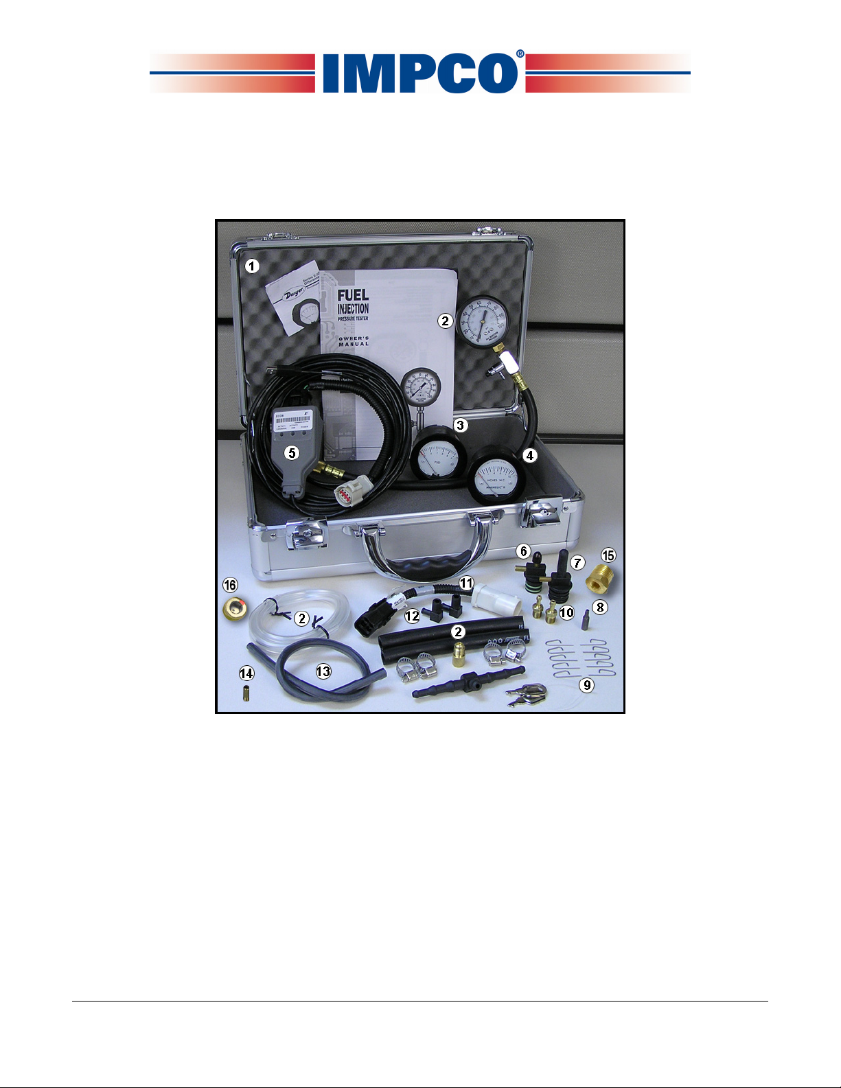
ITK-4 Kit and its components
The ITK-4 Test Kit (figure #1) was designed to replace both the ITK-2 and ITK-3 test kits and can be
used on both Spectrum Series II and Series III systems. The ITK-4 Test Kit incorporates a new dongle
(ECOM Cable P/N E2046002) to connect your Diagnostic Scan Tool (DST) to a Series II or Series III
equipped vehicle. The ECOM Cable is equipped with a Spectrum III DLC connector for direct series III
connection. To connect the ECOM Cable to a series II vehicle DLC you will need to use the adapter
cable (E1557400) included in the kit (refer to chapter II for complete instructions). The ECOM Cable is
Controller Area Network (CAN) enabled for high-speed connection to CAN enabled systems.
April, 2008 IMPCO Technologies Inc. PPI-105-REV.B
3030 South Susan St. Page 3 of 29
Santa Ana, CA 92704
www.impcotechnologies.com
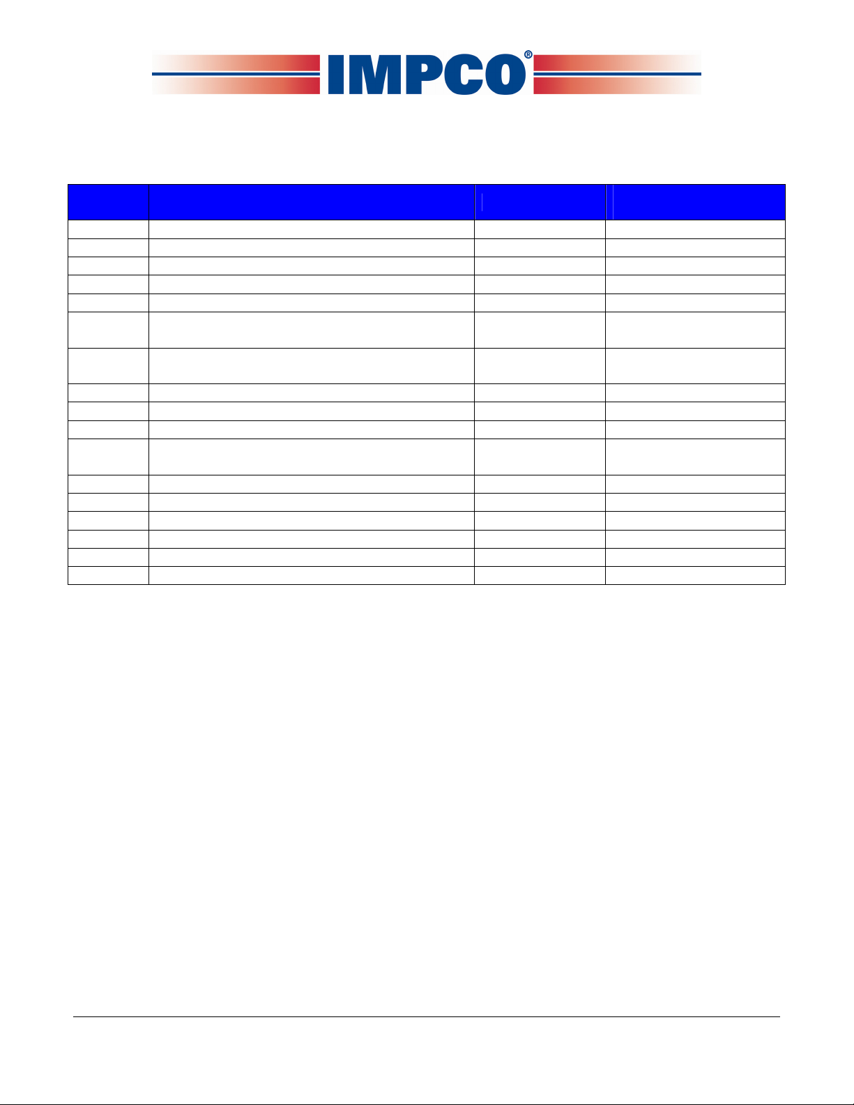
The ITK-4 Test Kit contains all items listed in table #1. If your kit is missing any component, or has any
damaged items, please call your OEM technical support group for instructions.
ITEM DESCRIPTION QTY USED IMPCO PART
NUMBER
1 Case, Metal, 14.25 x 9 x 4.25 1 C9-50724-001
2 Gauge, Test Gasoline Fuel System 1 TG-31119-001
3 Test Kit Gauge 0-5 PSID (2-5205) 1 TG-005
4 Test Kit Gauge 0-10” WC (2-5010) 1 TG-010
5 ASM, CAN Dongle (ECOM Cable) 1 E2046002
6 Fitting Assembly, Test Cap (System II LPR
Secondary Pressure Test Adapter) 1 AF4-31105
7 Assembly, Fitting Test Cap ¾” (System III
EPR Secondary Pressure Test Adapter) 1 AF4-50254-002
8 Tool, 20 IPR Torx-Plus Bit 1 T7-50172
9 Pin, Retainer 10 P1-30559
10 Fitting, 1/8” NPT / 3/16” HS Nip Brass 2 F4-4
11 Harness Adaptor, Spectrum II DLC to
Spectrum III Diagnostics Cable 1 E1557400
12 Fitting, 1/8” NPT ¼” HS El Nylon 2 F4-8
13 Hose, 3/16” ID Vacuum, Bulk 4 ft H1-11
14 Fitting, ¼ UNF, ¼ HS Vac Nip 1 F4-2
15 Brass Fitting 1 B3-26
16 Test Plug 1 P3-51214-001
NA User’s Manual, ITK-4 Test Kit 1 PPI-105
Table #1

PPI-105 REV B IMPCO Technologies Inc. April, 2008
Page 4 of 29 3030 South Susan St.
Santa Ana, CA 92704
www.impcotechnologies.com
Chapter II
ECOM Cable and DST Software Installation
A. Software Minimum Hardware Requirements:
Supported operating systems are:
Windows Vista
Windows XP
Windows 2000
Minimum processor speed:
Pentium II: 450 MHz
Pentium III: 1.0 GHz (Vista)
Minimum RAM requirement:
Windows Vista: 512 MB
Windows XP: 256 MB
Windows 2000: 128 MB
PC/laptop must have at least one available USB port (ECOM cable supports USB port only).
B. DST Software Installation:
NOTE: Before installing the DST software, close all other programs to ensure the installation
process will not be interrupted.
The ECOM software will be provided to you by your OEM supplier, internet download, CD, etc..
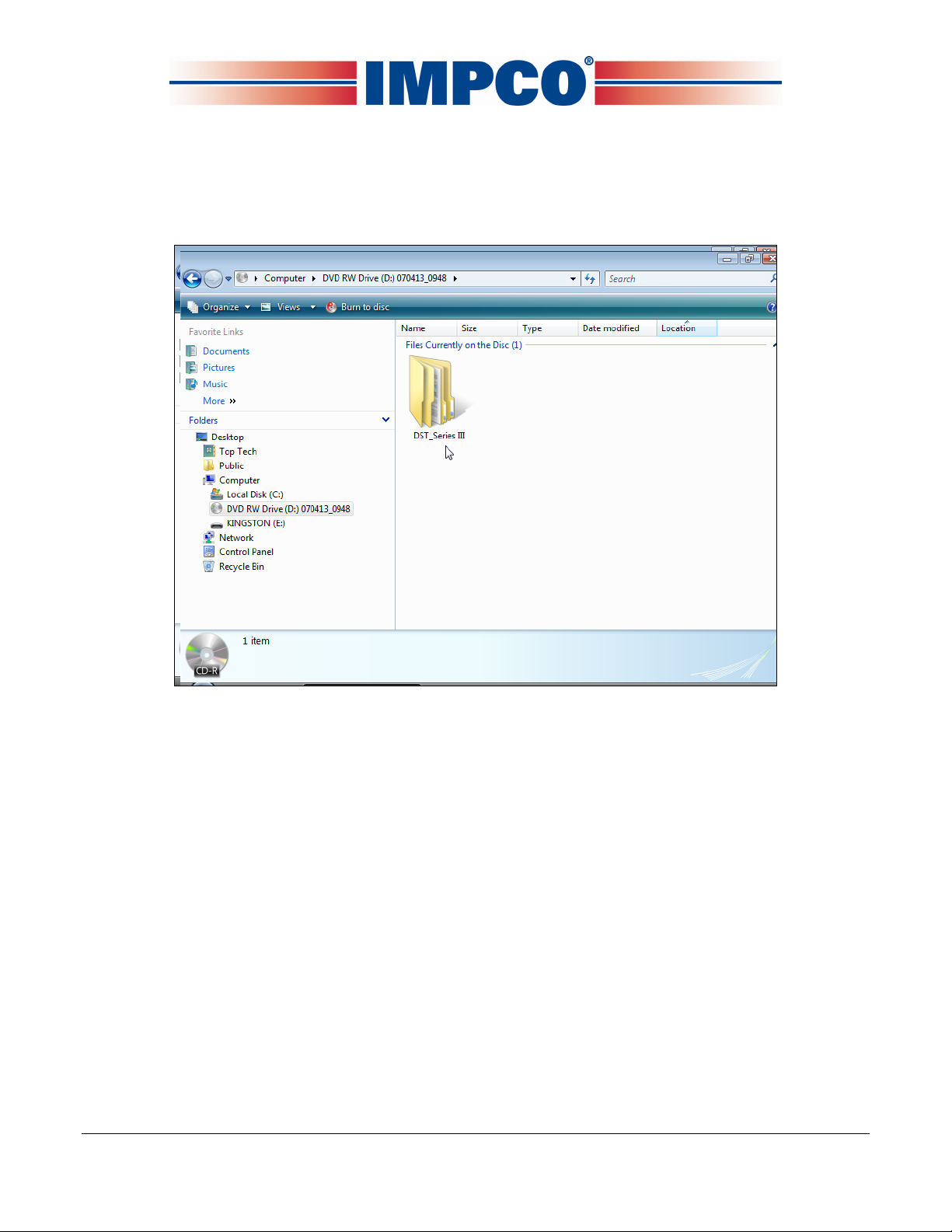
Regardless of the source, you must navigate to the DST_Series II or DST_Series III folder. Follow
the directions starting on the next page.

April, 2008 IMPCO Technologies Inc. PPI-105-REV.B
3030 South Susan St. Page 5 of 29
Santa Ana, CA 92704
www.impcotechnologies.com
•Open the DST_Series II or DST_Series III folder
•Open the Latest_GCP_Display folder

PPI-105 REV B IMPCO Technologies Inc. April, 2008
Page 6 of 29 3030 South Susan St.
Santa Ana, CA 92704
www.impcotechnologies.com
•Double click on “setup.exe” (application file) to start the windows installer. If a previous version
of the GCP software is installed, the uninstaller may remove the previous version and exit. You
will be required to start the installer again to install the new version.
•Click “Next” to continue

April, 2008 IMPCO Technologies Inc. PPI-105-REV.B
3030 South Susan St. Page 7 of 29
Santa Ana, CA 92704
www.impcotechnologies.com
•Click “Next” to continue
•Click “Next” to continue

PPI-105 REV B IMPCO Technologies Inc. April, 2008
Page 8 of 29 3030 South Susan St.
Santa Ana, CA 92704
www.impcotechnologies.com
•Click the “Finish” box to complete the installation.
•Click “Yes” to restart your computer

April, 2008 IMPCO Technologies Inc. PPI-105-REV.B
3030 South Susan St. Page 9 of 29
Santa Ana, CA 92704
www.impcotechnologies.com
•Once installed, the software can be accessed from Start Menu→Programs→
Impco GCP Display→Impco GCP Display
PPI-105 REV B IMPCO Technologies Inc. April, 2008
Page 10 of 29 3030 South Susan St.
Santa Ana, CA 92704
www.impcotechnologies.com
INSTALLING THE USB ADAPTER DRIVER
If your computer does not have an RS232 serial port you will need to install the USB adapter
driver. You do not need to install this driver if you plan to use the ECOM DLC cable.
•Open the DST_Series II or DST_Series III folder

April, 2008 IMPCO Technologies Inc. PPI-105-REV.B
3030 South Susan St. Page 11 of 29
Santa Ana, CA 92704
www.impcotechnologies.com
•Open the “USB Driver” folder
•Double click on “setup.exe” (application file) and follow the on screen prompts.
Installing the ECOM DLC cable driver
The ECOM USB cable is designed to replace both the serial DLC and the USB adapter cables. It
also provides communication to the ECM on the CAN line for systems that are CAN enabled. It
requires the installation of the ECOM driver and is compatible with the Series II and Series III DST
software programs.

PPI-105 REV B IMPCO Technologies Inc. April, 2008
Page 12 of 29 3030 South Susan St.
Santa Ana, CA 92704
www.impcotechnologies.com
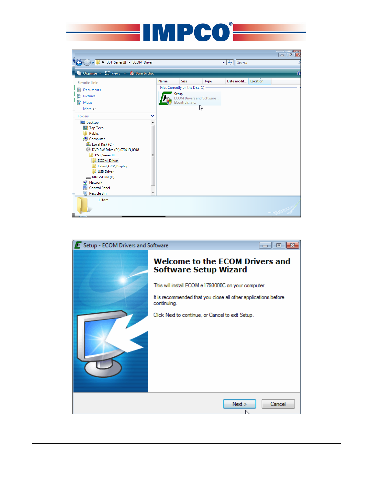
•Open the DST_Series II or DST_Series III folder
•Double click on ECOM_Driver
April, 2008 IMPCO Technologies Inc. PPI-105-REV.B
3030 South Susan St. Page 13 of 29
Santa Ana, CA 92704
www.impcotechnologies.com
•Double click on “setup.exe” (application file).
•Click “Next” to continue
PPI-105 REV B IMPCO Technologies Inc. April, 2008
Page 14 of 29 3030 South Susan St.
Santa Ana, CA 92704
www.impcotechnologies.com
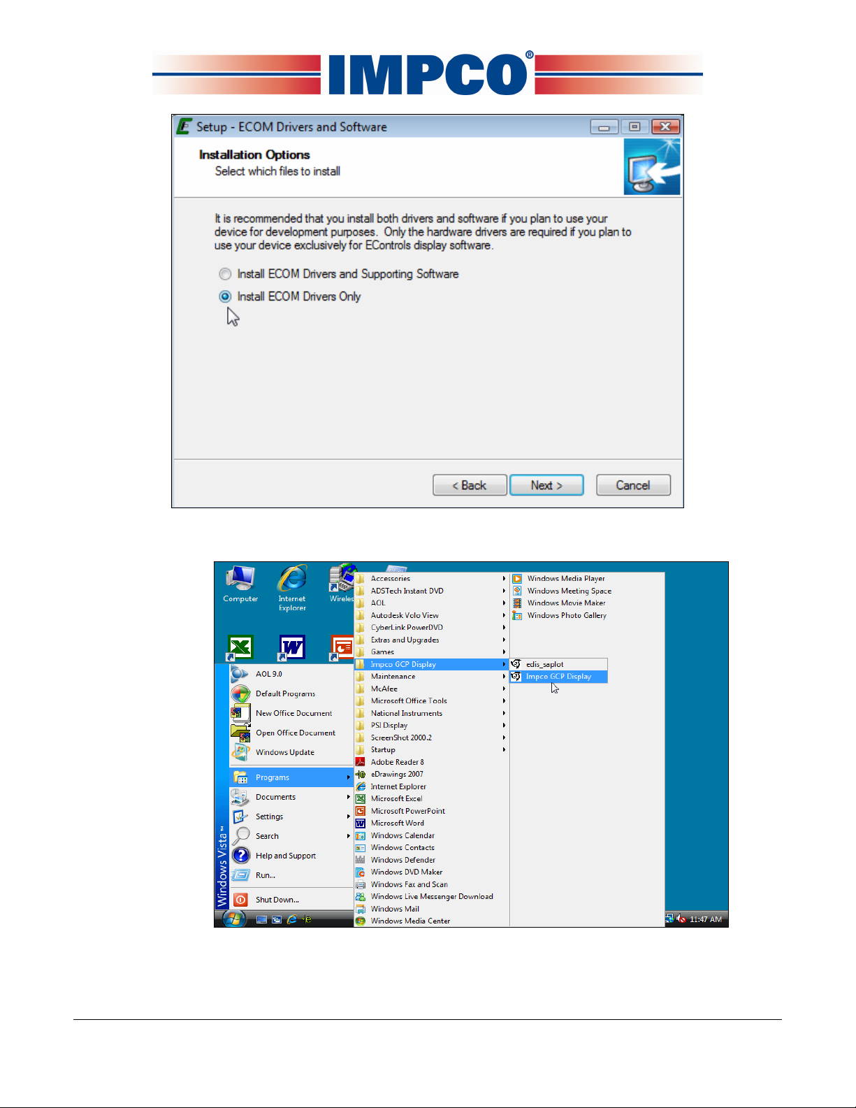
•Select install ECOM drivers only. Click “Next” and follow the on screen prompts.
•Open the DST software from Start Menu→Programs→Impco GCP Display→Impco GCP
Display.
April, 2008 IMPCO Technologies Inc. PPI-105-REV.B
3030 South Susan St. Page 15 of 29
Santa Ana, CA 92704
www.impcotechnologies.com
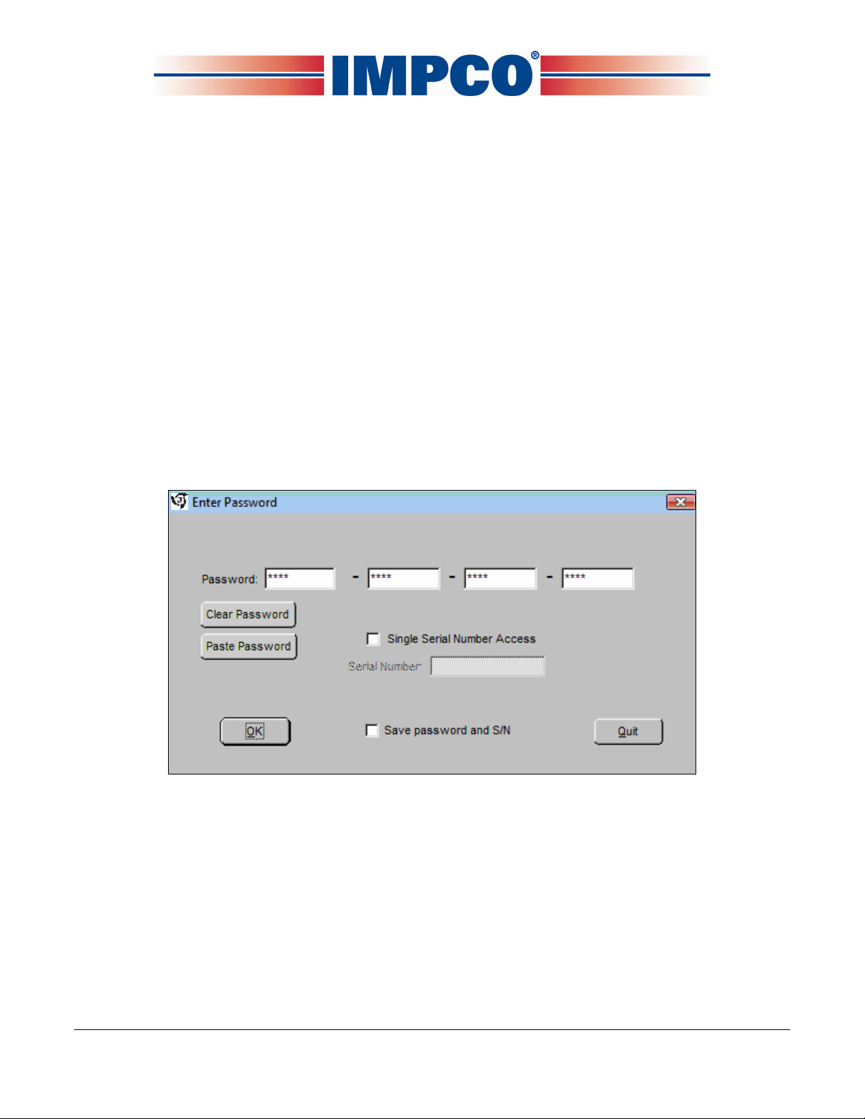
PASSWORD LOGIN
Figure 1 shows the password dialog box, which is displayed when a software session begins.
Login can be accomplished in two ways.
1. Enter an “All S/N Password” which is a password applicable to all ECMs of a given original
equipment manufacturer (OEM).
2. Enter a “Single S/N Password” and corresponding ECM serial number for a single ECM. A
Single Serial Number password is unique to a specific ECM serial number and permits
authorized service personnel to make changes or view information for a specific ECM.
3. In most instances the top “all” serial number boxes should be used for password entry. In this
case, do not check the single serial number box. Each password is a 16-character alpha-
numeric string specific to each Spectrum customer and determines which pages and variables
are visible through the software. Passwords are assigned by the OEM support group and may
change periodically. Check the “save password” box to automatically retain the password for
future use.
Figure 1: Populated Password Dialog Box

PPI-105 REV B IMPCO Technologies Inc. April, 2008
Page 16 of 29 3030 South Susan St.
Santa Ana, CA 92704
www.impcotechnologies.com
PASSWORD DIALOG BOX FUNCTIONS
•Clear Password Button Erases the current password from the password field.
•Paste Password Button Allows the user to copy a 16-character string from any word
processor and paste the string in the password field.
•Single Serial Number Access Checkbox Tells the software that the password is applicable for
single serial number access.
•Serial Number Field Only applicable when Single Serial Number Access Checkbox is checked.
The entry field must be populated for the 6-digit serial number for which the Single Serial
Number Access password applies (NOTE: Leading zeros included in the serial number are not
required).
•Save Password and S/N Checkbox Retains the password, and serial number (if applicable) for
the next software session.
Should an invalid password be entered, the error prompt shown in figure (2) will be
displayed and the software will not load. This prompt signifies the following:
•The All S/N password is invalid.
•The Single S/N password is incorrect for the Single Serial Number entered.
•An All S/N password is entered for Single Serial Number use.
•The Single Serial Number password is valid; however, the Single Serial Number Access
Checkbox is not checked.
Figure 2: Password Error Prompt

April, 2008 IMPCO Technologies Inc. PPI-105-REV.B
3030 South Susan St. Page 17 of 29
Santa Ana, CA 92704
www.impcotechnologies.com
If the Single S/N password entered is correct for the software but does not match the entered S/N
of the targeted ECM, the prompt in Figure 3 will be displayed.
Figure 3: Incorrect Serial Number Message
Figure 4 shows the communication status if a valid software password is entered when attempting
to connect to an ECM with a different key. In this instance the software will load but will not
connect to the target (ECM).
Figure 4: Not Authorized to Connect Message
In the event you receive this error message call your OEM support group for more information.
Connecting The PC To The Spectrum Fuel System
Connecting the DST cable

PPI-105 REV B IMPCO Technologies Inc. April, 2008
Page 18 of 29 3030 South Susan St.
Santa Ana, CA 92704
www.impcotechnologies.com
A laptop computer, with the diagnostic cable and software is the required tool for performing proper
diagnostic testing of the Spectrum fuel system. It is also used to monitor sensor and actuator
values and to read and clear Diagnostic Trouble codes. The DST software also performs several
special tests.
•Connect the system diagnostic cable to the RS232 port on the back of the computer. If you do
not have a RS232 port, use the USB to RS232 adapter supplied in the IMPCO ITK test kit. Be
sure to install the USB driver to enable the USB adapter for use with your computer.
•Connect the diagnostic cable to the DLC (diagnostic link connector) labeled in the electrical
schematic. The DLC is located on the engine harness. The new 8 pin DLC requires the use of
the 4 to 8 pin adapter included in the late model ITK test kits.
•Turn the computer ON.
•Start Windows.
•From the start menu select Programs→Impco GCP Display→Impco GCP Display
•Place the ignition key in the ON position.
Within several seconds the system Gauge screen should now appear and a green banner in the
upper left hand will read “Connected.”
Connecting to the PC using the ECOM cable

April, 2008 IMPCO Technologies Inc. PPI-105-REV.B
3030 South Susan St. Page 19 of 29
Santa Ana, CA 92704
www.impcotechnologies.com
•To connect using the ECOM cable you must select ECOM from the COM Port drop down menu.
•You will now need to configure the ECOM communication protocol.
•Select the CAN for systems with CAN enabled or serial for all others. Then select OK. You
are now ready to connect using the ECOM USB DLC cable.
PPI-105 REV B IMPCO Technologies Inc. April, 2008
Page 20 of 29 3030 South Susan St.
Santa Ana, CA 92704
www.impcotechnologies.com
Chapter III
Tool Usage Instructions
A. Fuel Pressure Gauge (TG-31119-001):
Refer to the fuel pressure gauge instruction booklet included in the ITK-4 Test Kit.
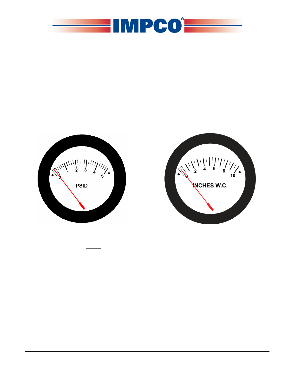
B. Differential Pressure Test Gauges (TG-005 & TG-010):
•Both the TG-005 (0-5 PSI) and the TG-010 (0-10” WC) are differential pressure gauges. This
means they can be used to measure the difference in pressures between two separate areas
or they can be used to measure either positive pressure or negative pressure (vacuum).
TG-005 TG-010
•Before using either of the differential pressure test gauges, they should to be calibrated against
a manometer or known calibrated gauge.
To calibrate a gauge:
Remove the front cover by unscrewing it in a counter-clockwise direction. You may need to
use a pair of channel lock style pliers (be careful as the cover is made of plastic). DO NOT use
any clamping tool on the body of the gauge.
Table of contents
Other Impco Test Equipment manuals


