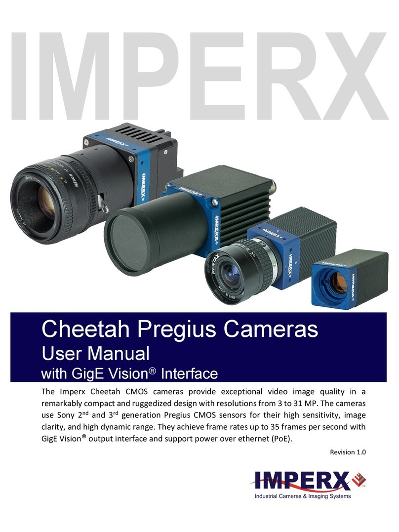
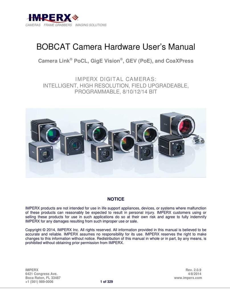
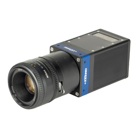
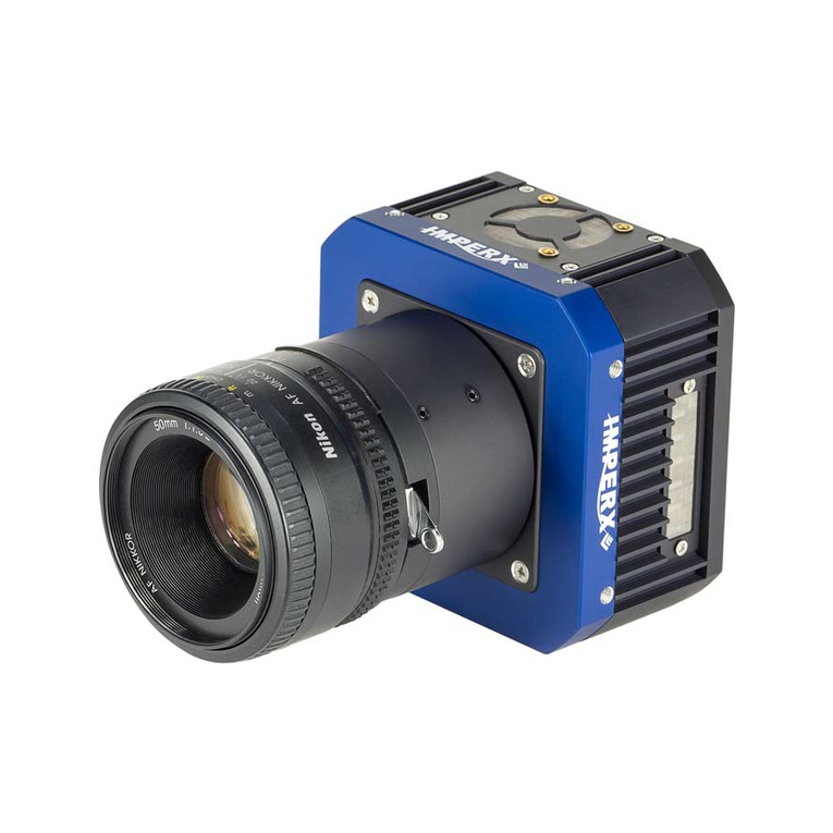
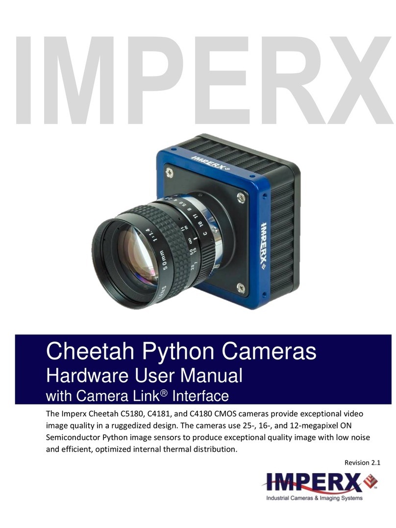
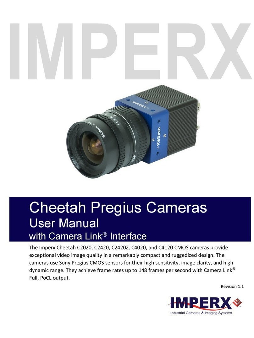
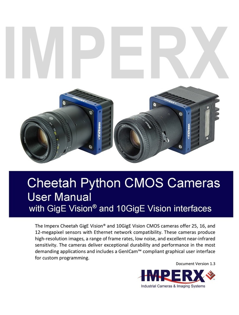
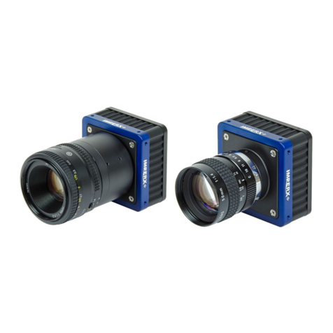
Imperx bobcat User manual

BOBCAT Hardware User’s Manual
Imperx, Inc. Rev. 2.0.2
6421 Congress Ave. 11/20/2012
Boca Raton, FL 33487
+1 (561) 989-0006 1 of 265
BOBCAT Hardware User’s Manual
(CameraLink PoCL, GEV, CoaXPress, and HD-SDI Models)
INTELLIGENT, HIGH-RESOLUTION, FIELD
UPGRADEABLE, PROGRAMMABLE, 8/10/12/14 BIT
DIGITAL CAMERAS
CONFIDENTIAL NOTICE:
These products are not intended for use in life support appliances, devices, or systems where malfunction of these
products can reasonably be expected to result in personal injury. Imperx customers using or selling these products for
use in such applications do so at their own risk and agree to fully indemnify Imperx for any damages resulting from
such improper use or sale.
Copyright © 2011, Imperx Inc. All rights reserved. All information provided in this manual is believed to be accurate
and reliable. Imperx assumes no responsibility for its use. Imperx reserves the right to make changes to this information
without notice. Redistribution of this manual in whole or in part, by any means, is prohibited without obtaining prior
permission from Imperx.

BOBCAT Hardware User’s Manual
Imperx, Inc. Rev. 2.0.6
6421 Congress Ave. 11/20/2012
Boca Raton, FL 33487
+1 (561) 989-0006 2 of 265
Revision History
Rev 0.2
03/23/09
P. Dinev
Initial Pre-Release –Old UART protocol
Rev 0.3
07/31/09
P. Dinev
Old UART removed, added new UART protocol and new
register addresses.
Rev 0.4
08/25/09
P. Dinev
Image Enhancement section, AOI8 modes added.
Rev 0.5
08/27/09
P. Dinev
Figure 2.27a and related text changed.
Rev 0.6
01/15/10
P. Dinev
B0620, B2520 cameras added, all related tables and figures
updated. Minor errors fixed.
Rev 0.7
03/02/10
P. Dinev
B1620, B1920 cameras added, all related tables and figures
updated. Minor errors fixed.
Rev 0.8
03/12/10
P. Dinev
B2020, B4020 and B4820 cameras added, all related tables
and figures updated. Minor errors fixed.
Rev 0.9
04/12/10
P. Dinev
GEV option added to all cameras, all related tables and
figures updated. Minor errors fixed.
Rev 1.0
04/25/10
P. Dinev
Official Release
Rev 1.1
10/10/10
P. Dinev
Minor errors fixed.
Rev 1.2
12/30/10
P. Dinev
Minor errors fixed. 3x8 RGB out and WB feature added
Rev 2.0
01/10/12
B. Gisonni
Minor errors fixed. Added cameras in Bobcat series –
B1310, B1411, B1020, B1320, B1621, B1921, B2320,
B3320, B4821 and B6620. Major feature TRUESENSE.
Rev 2.0.1
04/02/12
B.Gisonni
Minor errors fixed.
Rev 2.0.2
04/12/12
B.Gisonni
Minor errors fixed. Software Bit Toggle, CamConfig GUI
Basic and new screens.
Rev 2.0.3
09/18/12
A.Moreno
Warranty period changed from 1 year to 2 years.
Rev 2.0.4
09/26/12
A.Moreno
B2510, B1922 cameras added.
Rev 2.0.5
10/22/12
A.Moreno
B6640, B3340 4 tap cameras added. New Ordering Table

BOBCAT Hardware User’s Manual
Imperx, Inc. Rev. 2.0.6
6421 Congress Ave. 11/20/2012
Boca Raton, FL 33487
+1 (561) 989-0006 3 of 265
TABLE OF CONTENTS
BOBCAT HARDWARE USER’S MANUAL 1
CHAPTER 1 –INTRODUCTION 18
1.1 BOBCAT FAMILY............................................................................................................. 19
1.2 GENERAL DESCRIPTION .............................................................................................. 21
1.3 BOBCAT SPECIFICATIONS........................................................................................... 23
1.3.1 General Information .......................................................................................................... 23
1.3.2 Spectral Response.............................................................................................................. 26
1.3.3 Bayer and TRUESENSE Pattern Information................................................................... 29
1.3.4 Technical Specifications.................................................................................................... 30
1.4 CAMERA CONNECTIVITY ............................................................................................ 41
1.4.1 Camera Link Output.......................................................................................................... 41
1.4.2 GigE Output ...................................................................................................................... 46
1.4.3 Power Supply.................................................................................................................... 47
1.5 MECHANICAL, OPTICAL and ENVIRONMENTAL.................................................. 48
1.5.1 Mechanical........................................................................................................................ 48
1.5.2 Optical............................................................................................................................... 62
1.5.3 Environmental................................................................................................................... 62
CHAPTER 2 –CAMERA FEATURES 68
2.1 IMAGE RESOLUTION ..................................................................................................... 69
2.1.1 Normal Mode –Single Output.......................................................................................... 69
2.1.2 Normal Mode –Dual Output ............................................................................................ 70
2.1.3 Normal Mode –Quad Output ........................................................................................... 71
2.1.4 Center Mode...................................................................................................................... 72
2.2 FRAME TIME CONTROL ............................................................................................... 76
2.2.1 Internal Line and Frame Time Control.............................................................................. 76
2.2.2 Camera Speed Control....................................................................................................... 76
2.2.3 External Line and Frame Time Control ............................................................................ 78
2.3 AREA OF INTEREST........................................................................................................ 78
2.3.1 Horizontal and Vertical Window ...................................................................................... 78
2.3.2 Calculating the Frame Rate using Vertical Window......................................................... 81
BINNING ....................................................................................................................................... 105

BOBCAT Hardware User’s Manual
Imperx, Inc. Rev. 2.0.6
6421 Congress Ave. 11/20/2012
Boca Raton, FL 33487
+1 (561) 989-0006 4 of 265
2.4 EXPOSURE CONTROL.................................................................................................. 110
2.5.1 Internal Exposure Control - Electronic Shutter............................................................... 110
2.5.2 External exposure control................................................................................................ 110
2.5.3 Variable Frame Time –Programmable Line and Frame Time ....................................... 110
2.5.4 Automatic Exposure Control (AEC)............................................................................... 111
2.5.5 Automatic Iris Control (AIC).......................................................................................... 112
2.6 EXTERNAL TRIGGER................................................................................................... 113
2.6.1 Triggering Inputs.............................................................................................................. 113
2.6.2 Acquisition and Exposure Control................................................................................... 113
2.6.3 Trigger Strobe Control ..................................................................................................... 114
2.6.4 Triggering modes ............................................................................................................. 114
2.7 STROBE OUTPUT........................................................................................................... 119
2.8 GAIN and OFFSET........................................................................................................... 120
2.8.1 Analog Domain –manual control ................................................................................... 120
2.8.2 Digital Domain –manual control.................................................................................... 121
2.8.3 Automatic Gain Control (AGC)...................................................................................... 121
2.9 DATA OUTPUT FORMAT............................................................................................. 122
2.9.1 Bit Depth ......................................................................................................................... 122
2.9.2 Digital Data Shift............................................................................................................. 123
2.9.3 Output Format ................................................................................................................. 123
2.10 PULSE GENERATOR ..................................................................................................... 127
2.11 I/O CONTROL.................................................................................................................. 128
2.11.1 I/O Mapping ................................................................................................................... 128
2.11.2 Electrical Connectivity................................................................................................... 129
2.12 TEST IMAGE PATTERNS ............................................................................................. 131
2.12.1 Test Image patterns ........................................................................................................ 131
2.12.2 Image Superimposition................................................................................................... 131
2.13 WHITE BALANCE AND COLOR CONVERSION..................................................... 132
2.13.1 White Balance ................................................................................................................ 132
2.13.2 Color (Bayer to RGB) Conversion................................................................................ 132
2.14 DYNAMIC BLACK LEVEL CORRECTION AND TAP BALANCING................... 133
2.14.1 Black Level Correction ................................................................................................. 133
2.14.2 Tap Balancing................................................................................................................ 133
2.15 TRANSFER FUNCTION CORRECTION –USER LUT............................................. 134
2.15.1 Standard Gamma Correction......................................................................................... 134
2.15.2 User Defined LUT......................................................................................................... 135
BOBCAT Hardware User’s Manual
Imperx, Inc. Rev. 2.0.6
6421 Congress Ave. 11/20/2012
Boca Raton, FL 33487
+1 (561) 989-0006 5 of 265
2.16 DEFECTIVE PIXEL CORRECTION............................................................................ 136
2.16.1 Static Pixel Correction................................................................................................. 136
2.16.1 Dynamic Pixel Correction........................................................................................... 137
2.17 FLAT FIELD CORRECTION......................................................................................... 138
2.18 NEGATIVE IMAGE......................................................................................................... 140
2.19 CAMERA INTERFACE .................................................................................................. 141
2.19.1 Status LED .................................................................................................................. 141
2.19.2 Temperature Monitor .................................................................................................. 141
2.19.3 Exposure Time Monitor .............................................................................................. 141
2.19.4 Frame Time Monitor ................................................................................................... 142
2.19.5 Current image size....................................................................................................... 142
CHAPTER 3 –DIGITAL IMAGE PROCESSING 143
3.1 OVERVIEW ...................................................................................................................... 144
3.2 IMAGE ENHANCEMENT.............................................................................................. 144
3.2.1 Threshold Operation........................................................................................................ 144
3.2.2 Multi Point Correction..................................................................................................... 146
CHAPTER 4 –CAMERA CONFIGURATION 150
4.1 OVERVIEW ...................................................................................................................... 151
4.2 CAMERA CONFIGURATION....................................................................................... 151
4.2.1 Configuration Memory –parameter FLASH.................................................................. 151
4.2.3 Camera Serial Protocol.................................................................................................... 152
4.3 CAMERA CONFIGURATION REGISTER DESCRIPTION..................................... 156
4.3.1 Startup Procedure ............................................................................................................ 156
4.3.2 Saving and Restoring Settings......................................................................................... 156
4.3.3 Retrieving Manufacturing Data....................................................................................... 158
4.3.4 Camera Information Registers......................................................................................... 160
4.3.5 Image Size (AOI) Workspace Registers ......................................................................... 162
4.3.6 Exposure Control Workspace Registers.......................................................................... 169
4.3.7 AEC, AGC, AIC Workspace Registers........................................................................... 170
4.3.8 Video Amp, Gain and Offset Workspace Registers........................................................ 173
4.3.9 Triggering Workspace Registers..................................................................................... 176
4.3.10 Pulse Generator Workspace Registers ............................................................................ 179
4.3.11 Test Pattern Workspace Registers................................................................................... 180
4.3.12 Input/output Workspace Registers .................................................................................. 181
4.3.13 Output Data Format......................................................................................................... 186

BOBCAT Hardware User’s Manual
Imperx, Inc. Rev. 2.0.6
6421 Congress Ave. 11/20/2012
Boca Raton, FL 33487
+1 (561) 989-0006 6 of 265
4.3.14 White Balance Workspace Registers .......................................................................... 188
4.3.15 Color Conversion Workspace Registers...................................................................... 189
4.3.16 Data Correction Workspace Registers ........................................................................ 190
4.4 DATA PROCESSING REGISTER DESCRIPTION.................................................... 191
4.4.1 Image Enhancement Workspace Registers ..................................................................... 191
4.5 LENS CONTROLLER REGISTER DESCRIPTION..........Error! Bookmark not defined.
4.5.1 Lens Controller Workspace Registers................................Error! Bookmark not defined.
CHAPTER 5 - CONFIGURATOR FOR CAMERALINK 194
5.1 OVERVIEW ...................................................................................................................... 195
5.2 DISCOVERY PROCEDURE........................................................................................... 195
5.3 GRAPHICAL USER INTERFACE ................................................................................ 196
5.4 MAIN GUI MENU............................................................................................................ 198
5.5 VIEW GUI WINDOWS.................................................................................................... 202
5.6 GUI HELP.......................................................................................................................... 203
5.7 PARAMETER WINDOWS.............................................................................................. 204
5.7.1 Video Amp.................................................................................................................. 204
5.7.2 I/O Control .................................................................................................................. 205
5.7.3 Trigger......................................................................................................................... 207
5.7.4 Pulse Generator ........................................................................................................... 209
5.7.5 Exposure...................................................................................................................... 210
5.7.6 Test Image................................................................................................................... 212
5.7.7 Area of Interest (AOI)................................................................................................. 213
5.7.8 Strobe Control............................................................................................................. 215
5.7.9 Color............................................................................................................................ 216
5.7.10 Processing.................................................................................................................... 217
5.7.11 Data Output ................................................................................................................. 220
5.7.12 Lens Control...................................................................Error! Bookmark not defined.
CHAPTER 6 –GEN<I>CAM REFERENCE MANUAL 222
6.1 INTRODUCTION............................................................................................................. 223
6.2 NODE TREE...................................................................................................................... 224
6.2.1 Device Information.......................................................................................................... 224
6.2.2 IP Engine......................................................................................................................... 224

BOBCAT Hardware User’s Manual
Imperx, Inc. Rev. 2.0.6
6421 Congress Ave. 11/20/2012
Boca Raton, FL 33487
+1 (561) 989-0006 7 of 265
6.2.3 GigE Vision Transport Layer.......................................................................................... 224
6.2.5 Acquisition and Trigger Controls.................................................................................... 226
6.2.6 Counters and Timers Controls......................................................................................... 226
6.2.7 Analog Controls .............................................................................................................. 227
6.2.8 Test Mode........................................................................................................................ 227
6.2.9 User Sets.......................................................................................................................... 227
6.2.10 Custom Features.............................................................................................................. 228
CHAPTER 7 –BOBCAT WARRANTY AND SUPPORT 231
7.1 ORDERING INFORMATION........................................................................................ 232
7.2 TECHNICAL SUPPORT................................................................................................. 233
7.3 WARRANTY..................................................................................................................... 234
APPENDIX A –CAMERA CONFIGURATION REFERENCE 235
A.0 ABBREVIATIONS ........................................................................................................... 236
A.1 SAVING AND RESTORING REGISTERS................................................................... 236
A.2 CAMERA INFORMATION REGISTERS .................................................................... 236
A.3 IMAGE SIZE (AOI) REGISTERS.................................................................................. 237
A.4 EXPOSURE CONTROL REGISTERS.......................................................................... 238
A.5 VIDEO REGISTERS........................................................................................................ 238
A.6 AEC, AGC, AIC REGISTERS ........................................................................................ 239
A.7 TRIGGER REGISTERS.................................................................................................. 239
A.8 PULSE GENERATOR REGISTERS ............................................................................. 240
A.9 TEST PATTERN REGISTERS....................................................................................... 240
A.10 STROBE REGISTERS..................................................................................................... 240
A.11 INPUT AND OUTPUT REGISTERS ............................................................................. 241
A.12 OUTPUT DATA FORMAT REGISTERS ..................................................................... 241
A.13 WB AND COLOR CORRECTION REGISTERS......................................................... 241

BOBCAT Hardware User’s Manual
Imperx, Inc. Rev. 2.0.6
6421 Congress Ave. 11/20/2012
Boca Raton, FL 33487
+1 (561) 989-0006 8 of 265
A.14 DATA CORRECTION REGISTERS............................................................................. 242
A.15 PROCESSING REGISTERS........................................................................................... 242
A.16 MANUFACTURING DATA REGISTERS.................................................................... 242
APPENDIX B –CREATING LOOK UP TABLES 243
B.1 OVERVIEW ...................................................................................................................... 244
B.2 USING AN ASCII TEXT EDITOR................................................................................. 244
B.3 USING MICROSOFT EXCEL........................................................................................ 245
APPENDIX C –CREATING DPC AND HPC TABLES 246
C.1 OVERVIEW ...................................................................................................................... 247
C.2 USING AN ASCII TEXT EDITOR................................................................................. 247
APPENDIX D –SOFTWARE INSTALLATION - CL 248
APPENDIX E –FIRMWARE UPGRADE - CL 250
E.1 OVERVIEW ...................................................................................................................... 251
E.2 BOBCAT UPGRADE ....................................................................................................... 251
APPENDIX F –GIGE VISION FIRMWARE UPGRADE 255
F-1 Overview:.............................................................................................................................. 256
F-2 RGS Upgrade........................................................................................................................ 259
F-3 IP Engine Install.................................................................................................................... 260
APPENDIX G –POWER SUPPLIES 262

BOBCAT Hardware User’s Manual
Imperx, Inc. Rev. 2.0.6
6421 Congress Ave. 11/20/2012
Boca Raton, FL 33487
+1 (561) 989-0006 9 of 265
FIGURES
Figure 1.0a –Interline CCD pixel structure. 24
Figure 1.0b –Kodak TRUESENSE color filter interline CCD pixel structure. 24
Figure 1.1a –KAI (Kodak) CCD typical mono spectral response. 26
Figure 1.1b –KAI (Kodak) CCD typical UV spectral response. 26
Figure 1.1c –KAI (Kodak) CCD typical color spectral response. 27
Figure 1.1d –KODAK TRUESENSE CCD typical spectral response with AR coated cover
glass. 27
Figure 1.2a –ICX (SONY) CCD typical mono spectral response. 28
Figure 1.2b –ICX (Sony) CCD typical color spectral response. 28
Figure 1.3 –Bayer Pattern arrangement. 29
Figure 1.3a –Kodak TRUESENSE Pattern arrangement. 29
Figure 1.4 –Camera back panel –camera link output 41
Figure 1.5a –Camera output connector 42
Figure 1.4a –Camera power connector 44
Figure 1.6 –Camera back panel –GigE output 46
Figure 1.7a –C-mount camera link cameras. 48
Figure 1.7b –C-mount GEV cameras. 48
Figure 1.8a –C-mount camera link output –dimensional drawings for ICL-B0610, B0620,
B1310, B1410, B1411, B1610, B2510, and B2520. 49

BOBCAT Hardware User’s Manual
Imperx, Inc. Rev. 2.0.6
6421 Congress Ave. 11/20/2012
Boca Raton, FL 33487
+1 (561) 989-0006 10 of 265
Figure 1.8b –C-mount camera link output –dimensional drawings for ICL-B1620 50
and ICL-B1920. 50
Figure 1.8ba –C-mount camera link output –dimensional drawings for ICL-B1020, B1320,
B1621, B1921, B1922, and B2320. 51
Figure 1.8c –F-mount camera link output –dimensional drawings for ICL-B2020, 52
ICL-B4020 and ICL-B4820. 52
Figure 1.8ca –F-mount camera link output –dimensional drawings for ICL-B3320, 53
ICL-B4821 and ICL-B6620. 53
Figure 1.8cb –F-mount camera link output –dimensional drawings for ICL-B3340, 54
and ICL-B6640. 54
Figure 1.8cc –F-mount camera link output –with external heatsink dimensional drawings
for 55
Figure 1.8d –C-mount GigE vision output –dimensional drawings for IGV-B0610, 56
IGV-B0620, IGV-B1410, IGV-B1610, B2510, and B2520. 56
Figure 1.8e –C-mount GigE vision output –dimensional drawings for IGV-B1620, 57
and IGV-B1920. 57
Figure 1.8ea –C-mount GigE vision output –dimensional drawings for IGV-B1020, B1320,
B1621, B1921, B1922, and B2320. 58
Figure 1.8f –F-mount GigE vision output –dimensional drawings for IGV-B2020, 59
IGV-B4020 and IGV-B4820. 59
Figure 1.8fa –F-mount GigE vision output –dimensional drawings for IGV-B3320, 60

BOBCAT Hardware User’s Manual
Imperx, Inc. Rev. 2.0.6
6421 Congress Ave. 11/20/2012
Boca Raton, FL 33487
+1 (561) 989-0006 11 of 265
IGV-B4821 and IGV-B6620. 60
Figure 1.8g –Small Bobcat mounting plate using ¼ in 20 thread. 61
Figure 1.8ga –Big Bobcat mounting plate using ¼ in 20 thread. 61
Figure 1.9a –Optical plane position for B0610 (KAI-0340), B0620 (KAI-0340), B1410 (ICX-
285), B1610 (ICX-274), B2510 (ICX-655), and B2520 (ICX-625) cameras. 63
Figure 1.9b –Optical plane position for B1620 (KAI-2020) and B1920 (KAI-2093) cameras.
64
Figure 1.9c –Optical plane position for B2020 (KAI-04022), B4020 (KAI-11002), and
B4820 (KAI-16000) cameras. 65
Figure 1.9d –Optical plane position for B1020 (KAI-01050, B1621 (02050), B1921 (02150)
B1922 (ICX-674), and B2320 (04050) cameras. 66
Figure 1.9e –Optical plane position (in mm) for B3320 (KAI- 08050). 67
Figure 1.9f –Optical plane position (mm) for B4821(KAI-16050) and B6620 (KAI-29050).
67
Figure 2.1 –Single output mode of operation. 69
Figure 2.2 –Dual output mode of operation. 70
Figure 2.3 –Quad output operation. 71
Figure 2.4 –Center columns output mode of operation. 73
Figure 2.4 –Center columns output in dual mode of operation. 73
Figure 2.5 –Center columns output in dual tap mode. 74
Figure 2.6 –Sub-sampled CCD output. 75
Figure 2.7 –Horizontal and vertical window positioning. 78

BOBCAT Hardware User’s Manual
Imperx, Inc. Rev. 2.0.6
6421 Congress Ave. 11/20/2012
Boca Raton, FL 33487
+1 (561) 989-0006 12 of 265
Figure 2.8 –Slave AOIs. 79
Figure 2.9 –PAOI enabled as processing ROI. 80
Figure 2.10.1a –Frame rate vs. vertical window size for B0610 81
Figure 2.10.1b –Frame rate vs. Vertical window size for B0620 82
Figure 2.10.1c –Frame rate vs. Vertical window size for B1020 83
Figure 2.10.1d –Frame rate vs. Vertical window size for B1310 84
Figure 2.10.1e –Frame rate vs. Vertical window size for B1320 85
Figure 2.10.1f –Frame rate vs. Vertical window size for B1410 86
Figure 2.10.1g –Frame rate vs. Vertical window size for B1411 87
Figure 2.10.1h –Frame rate vs. Vertical window size for B1610 88
Figure 2.10.1i –Frame rate vs. Vertical window size for B1620 89
Figure 2.10.1j –Frame rate vs. Vertical window size for B1621 90
Figure 2.10.1k –Frame rate vs. Vertical window size for B1920 91
Figure 2.10.1l –Frame rate vs. Vertical window size for B1921 92
Figure 2.11.1m –Frame rate vs. Vertical window size for B1922 93
Figure 2.12.1n –Frame rate vs. vertical window size for B2510 94
Figure 2.10.1o –Frame rate vs. vertical window size for B2520 95
Figure 2.10.1p –Frame rate vs. vertical window size for B2020 96
Figure 2.10.1q –Frame rate vs. vertical window size for B2320 97
Figure 2.10.1r –Frame rate vs. vertical window size for B3320 98

BOBCAT Hardware User’s Manual
Imperx, Inc. Rev. 2.0.6
6421 Congress Ave. 11/20/2012
Boca Raton, FL 33487
+1 (561) 989-0006 13 of 265
Figure 2.10.1s –Frame rate vs. vertical window size for B3340 99
Figure 2.10.1t –Frame rate vs. vertical window size for B4020. 100
Figure 2.10.1u –Frame rate vs. vertical window size for B4820. 101
Figure 2.10.1v –Frame rate vs. vertical window size for B4821. 102
Figure 2.10.1w –Frame rate vs. vertical window size for B6620. 103
Figure 2.10.1x –Frame rate vs. vertical window size for B6640. 104
Figure 2.11 –2:2 Horizontal and vertical binning 105
Figure 2.11a –AOI within horizontal and vertical binned image. 109
Figure 2.12 –Electronic shutter position 110
Figure 2.13 –Programmable frame time 111
Figure 2.14 –Standard triggering timing 115
Figure 2.15 –Fast synchronized triggering - rapid capture 116
Figure 2.16 –Double exposure triggering 117
Figure 2.17 –Frame accumulation triggering 118
Figure 2.18 –Asynchronous triggering 118
Figure 2.19 –Strobe pulse positioning 119
Figure 2.20 –AFE gain and offset 120
Figure 2.21 –DATA output format 122
Figure 2.22 –Output data using 4 bits digital right shift 123
Figure 2.24a –2 tap sequential output 124

BOBCAT Hardware User’s Manual
Imperx, Inc. Rev. 2.0.6
6421 Congress Ave. 11/20/2012
Boca Raton, FL 33487
+1 (561) 989-0006 14 of 265
Figure 2.24b –2 tap interleaved output 125
Figure 2.24c –2 tap interleaved output 125
Figure 2.24d –4 tap interleaved output 126
Figure 2.25 –Internal pulse generator 127
Figure 2.26 –IN1, IN2 electrical connection. 129
Figure 2.27 –OUT1, OUT2 electrical connection. 129
Figure 2.30 –Look up table 134
Figure 2.31 –Gamma corrected video signal 135
Figure 2.32 –Custom LUT 135
Figure 2.33a –Original image showing ‘shading’ effect 139
Figure 2.33b –Flat field corrected image 139
Figure 2.34 –Normal and Negative Image 140
Figure 3.1 –Original and processed image with single threshold. 145
Figure 3.2 –Original and processed image with double threshold. 145
Figure 3.3 –Original and processed image with threshold and gray scale stretch. 146
Figure 3.4 –Single point TF correction. 147
Figure 3.5 –Multi point TF correction. 148
Figure 3.6 –Multi point image correction (a –original, b –processed). 149
Figure 4.1 –Serial protocol format 152
Figure 4.2 –Normal write cycle 153

BOBCAT Hardware User’s Manual
Imperx, Inc. Rev. 2.0.6
6421 Congress Ave. 11/20/2012
Boca Raton, FL 33487
+1 (561) 989-0006 15 of 265
Figure 4.3a –Invalid command error 153
Figure 4.3b –Rx timeout error 153
Figure 4.4 –Normal read cycle 154
Figure 5.1 –Discovery procedure –select port 195
Figure 5.2 –CamConfig GUI Advanced 196
Figure 5.2a –CamConfig GUI Basic 197
Figure 5.3 –Main Menu 198
Figure 5.5 –Command terminal 200
Figure 5.6 –Download terminal 201
Figure 5.7 –View GUI Windows 202
Figure 5.8 –Help menu 203
Figure 5.9 –About CamConfig. 203
Figure 5.10 –Video Amp parameter window 204
Figure 5.11 –I/O control parameter window 206
Figure 5.13 –Pulse generator window 209
Figure 5.16 –AOI window. 214
Figure 5.17 –Strobe Control window 215
Figure 5.18 –Color window 217
Figure 5.20 –Data output window 220
Figure 5.21 –Lens Control window Error! Bookmark not defined.

BOBCAT Hardware User’s Manual
Imperx, Inc. Rev. 2.0.6
6421 Congress Ave. 11/20/2012
Boca Raton, FL 33487
+1 (561) 989-0006 16 of 265
TABLES AND CAPTIONS
Table 1.0 –Pixel structure for different BOBCAT cameras 25
Table 1.1a –B0610, B0620 Camera Specifications. 32
Table 1.1b –B1020, B1310 and B1320 Camera Specifications 33
Table 1.1c –B1410 and B1411 Camera Specifications 34
Table 1.1d –B1610, B1620 and B1621 Camera Specifications 35
Table 1.1e –B1920,B1921 and B1922 Camera Specifications 36
Table 1.1f –B2020, B2320 and B2510 Camera Specifications 37
Table 1.1g –B2520, B3320 and B4020 Camera Specifications 38
Table 1.1h –B4820, B4821 and B6620 Camera Specifications 39
Table 1.1i –B6640,B3340 Quad Camera Specifications 40
Table 1.2 –Camera Output Connector –Signal Mapping 42
Table 1.3 –Base Camera Link bit assignment 43
Table 1.4b –Camera Power Connector Pin Mapping 44
Table 1.5a –BNC Connectors Pin Mapping 45
Table 2.1 –Image resolutions for different modes 75
Table 2.2 –Frame rates for different modes 77
Table 2.3 –Frame rates for quad output cameras 77
Table 2.4a –Image sizes and frame rates for different H binning modes 106

BOBCAT Hardware User’s Manual
Imperx, Inc. Rev. 2.0.6
6421 Congress Ave. 11/20/2012
Boca Raton, FL 33487
+1 (561) 989-0006 17 of 265
Table 2.4b –Image sizes and frame rates for different V binning modes 107
Table 2.4c –B0620 Center mode image sizes and frame rates during V binning 107
Table 2.4a –BOBCAT Input Mapping 128
Table 2.4b –BOBCAT Output Mapping 128
Table 3.1 –Current camera temperature values 162
Table 4.0 –Auto Iris 4 pin MINI plug E4-191J 265

BOBCAT Hardware User’s Manual
Imperx, Inc. Rev. 2.0.6
6421 Congress Ave. 11/20/2012
Boca Raton, FL 33487
+1 (561) 989-0006 18 of 265
Chapter 1 –Introduction
Introduction
This chapter outlines the key features of the BOBCAT camera.

BOBCAT Hardware User’s Manual
Imperx, Inc. Rev. 2.0.6
6421 Congress Ave. 11/20/2012
Boca Raton, FL 33487
+1 (561) 989-0006 19 of 265
1.1 BOBCAT FAMILY
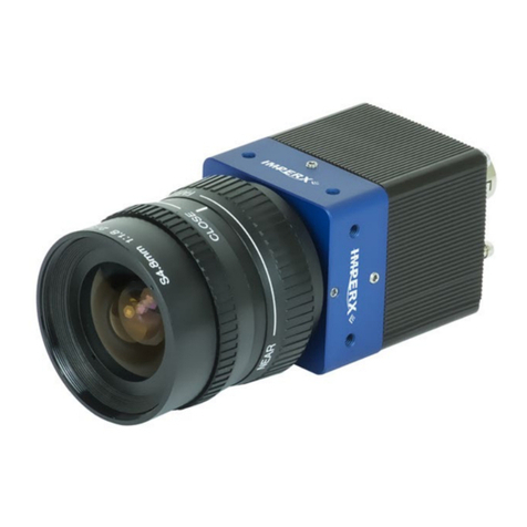
The BOBCAT series of cameras are built around a robust imaging platform utilizing the
latest digital technology and components. BOBCAT camera series is designed around 20
different CCD imaging sensors, featuring different resolutions and frame rates. Each base
model is available in monochrome and color. Each base model is also available with Base
Camera Link PoCL output and GEV. The first three letters in the camera model name shows
the output interface –ICL for Camera Link, and IGV –for GigE Vision.
The BOBCAT family list is shown below:
Model
Resolution
Speed
Type
Optics
CCD
CCD model
ICL-B0610M
648/640 x 488/480
110/138 fps
Mono
1/3"
Kodak
KAI-0340SM
ICL-B0610C
648/640 x 488/480
110/138 fps
Color
1/3"
Kodak
KAI-0340SC
ICL-B0620M
648/640 x 488/480
210/260 fps
Mono
1/3"
Kodak
KAI-0340DM
ICL-B0620C
648/640 x 488/480
210/260 fps
Color
1/3"
Kodak
KAI-0340DC
ICL-B1020M
1032/1024 x 1032/1024
60/74 fps
Mono
1/2'”
Kodak
KAI-01050M
ICL-B1020C
1032/1024 x 1032/1024
60/74 fps
Color
1/2'”
Kodak
KAI-01050C
ICL-B1310M
1296/1280 x 966/960
26/39 fps
Mono
1/3”
Sony
ICX-445AL
ICL-B1310C
1296/1280 x 966/960
26/39 fps
Color
1/3”
Sony
ICX-445AQ
ICL-B1320M
1320/1280 x 736/720
68/85 fps
Mono
1/2'”
Kodak
KAI-01150M
ICL-B1320C
1320/1280 x 736/720
68/85 fps
Color
1/2'”
Kodak
KAI-01150C
ICL-B1410M
1392/1360 x 1040/1024
23/30 fps
Mono
2/3"
Sony
ICX-285AL
ICL-B1410C
1392/1360 x 1040/1024
23/30 fps
Color
2/3"
Sony
ICX-285AQ
ICL-B1411M
1392/1360 x 1040/1024
24/31 fps
Mono
1/2'”
Sony
ICX-267AL
ICL-B1411C
1392/1360 x 1040/1024
24/31 fps
Color
1/2'”
Sony
ICX-267AK
ICL-B1610M
1628/1620 x 1236/1220
16/25 fps
Mono
1/1.8"
Sony
ICX-274ALM
ICL-B1610C
1628/1620 x 1236/1220
16/25 fps
Color
1/1.8"
Sony
ICX-274AQC
ICL-B1620M
1608/1600 x 1208/1200
35/44 fps
Mono
1.0"
Kodak
KAI-2020M
ICL-B1620C
1608/1600 x 1208/1200
35/44 fps
Color
1.0"
Kodak
KAI-2020C
ICL-B1621M
1632/1600 x 1232/1200
34/42 fps
Mono
2/3”
Kodak
KAI-02050M
ICL-B1621C
1632/1600 x 1232/1200
34/42fps
Color
2/3”
Kodak
KAI-02050C
ICL-B1920M
1920 x 1080
33/41 fps
Mono
1.0"
Kodak
KAI-2093M
ICL-B1920C
1928/1920 x 1084/1080
33/41 fps
Color
1.0"
Kodak
KAI-2093C
ICL-B1921M
1952/1920 x 1112/1080
32/40 fps
Mono
2/3”
Kodak
KAI-02150M
ICL-B1921C
1952/1920 x 1112/1080
32/40 fps
Color
2/3”
Kodak
KAI-02150C
ICL-B1922M
1940/1932 1460/1452
20/27 fps
Mono
2/3”
Sony
ICX-674
ICL-B1922C
1940/1932 1460/1452
20/27 fps
Color
2/3”
Sony
ICX-674
ICL-B2020M
2056/2048 x 2060/2048
16/20 fps
Mono
1.3"
Kodak
KAI-04022M
ICL-B2020C
2056/2048 x 2060/2048
16/20 fps
Color
1.3"
Kodak
KAI-04022C
ICL-B2320M
2352/2336 x 1768/1752
16/21 fps
Mono
1”
Kodak
KAI-04050M
ICL-B2320C
2352/2336 x 1768/1752
16/21 fps
Color
1”
Kodak
KAI-04050C
ICL-B2510M
2456/2448 x 2058/2050
6.5/9.6 fps
Mono
2/3"
Sony
ICX-655AL
ICL-B2510C
2456/2448 x 2058/2050
6.5/9.6 fps
Color
2/3"
Sony
ICX-655AL
ICL-B2520M
2456/2448 x 2058/2050
11/16 fps
Mono
2/3"
Sony
ICX-625AL
ICL-B2520C
2456/2448 x 2058/2050
11/16 fps
Color
2/3"
Sony
ICX-625AQ
ICL-B3320M
3312/3296 x 2496/2472
8.5/10.7 fps
Mono
4/3”
Kodak
KAI-08050M

BOBCAT Hardware User’s Manual
Imperx, Inc. Rev. 2.0.6
6421 Congress Ave. 11/20/2012
Boca Raton, FL 33487
+1 (561) 989-0006 20 of 265
Model
Resolution
Speed
Type
Optics
CCD
CCD model
ICL-B3320C
3312/3296 x 2496/2472
8.5/10.6 fps
Color
4/3”
Kodak
KAI-08050C
ICL-B3340M
3312/3296 x 2496/2472
17.05/21.3
Color
4/3”
Kodak
KAI-08050C
ICL-B3340C
3312/3296 x 2496/2472
17.05/21.3
Color
4/3”
Kodak
KAI-08050C
ICL-B4020M
4032/4008 x 2688/2672
5/7 fps
Mono
43.3 mm
Kodak
KAI-11002M
ICL-B4020C
4032/4008 x 2688/2672
5/7 fps
Color
43.3 mm
Kodak
KAI-11002C
ICL-B4820M
4904/4872 x 3280/3248
3.2/4.2fps
Mono
43.3 mm
Kodak
KAI-16000M
ICL-B4820C
4904/4872 x 3280/3248
3.2/4.2 fps
Color
43.3 mm
Kodak
KAI-16000C
ICL-B4821M
4920/4896 x 3280/3264
3.1/4.2 fps
Mono
32.36 mm
Kodak
KAI-16050M
ICL-B4821C
4920/4896 x 3280/3264
3.1/4.2 fps
Color
32.36 mm
Kodak
KAI-16050C
ICL-B6620M
6600/6576 x 4400/4384
1.8/2.5 fps
Mono
43.3 mm
Kodak
KAI-29050M
ICL-B6620C
6600/6576 x 4400/4384
1.8/2.5 fps
Color
43.3 mm
Kodak
KAI-29050C
ICL-B6640M
6600/6576 x 4400/4384
3.5/4.7 fps
Mono
43.3 mm
Kodak
KAI-29050M
ICL-B6640C
6600/6576 x 4400/4384
3.5/4.7 fps
Color
43.3 mm
Kodak
KAI-29050C
NOTE:
1. Since the camera features and performance are output invariant, when describing the
cameras we will use only the model number without the first three letters.
2. B1920 supports only 1920 x 1080 image size.
This manual suits for next models
4
Table of contents
Other Imperx Digital Camera manuals

Imperx
Imperx LYNX IPX-VGA120-L User manual

Imperx
Imperx Cheetah C5180 Instructions for use

Imperx
Imperx Cheetah Series User manual

Imperx
Imperx Cheetah Series User manual

Imperx
Imperx CXP-C5180M User manual

Imperx
Imperx Cheetah 3G-SDI User manual

Imperx
Imperx Cheetah Pregius Series User manual

Imperx
Imperx Cheetah Python Series User manual

Imperx
Imperx bobcat hd-sdi User manual

Imperx
Imperx LYNX Instructions for use