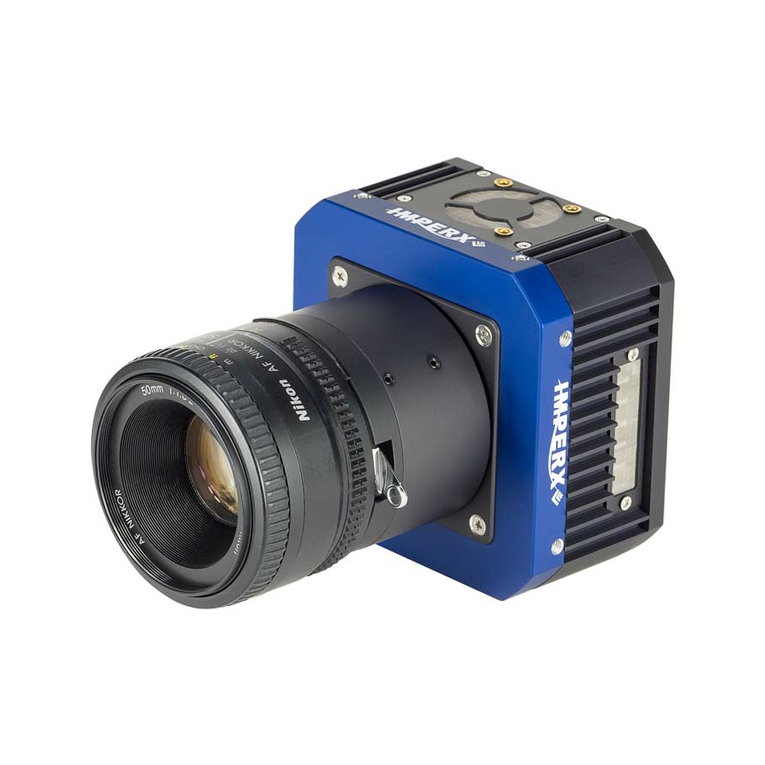
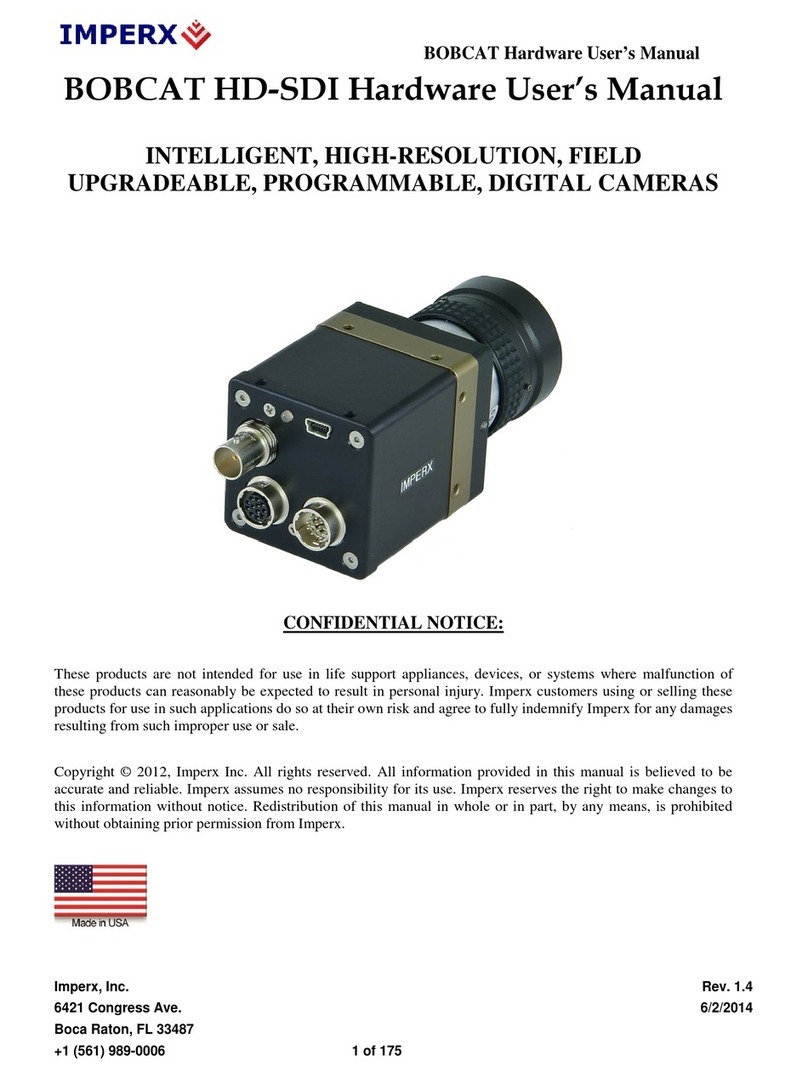
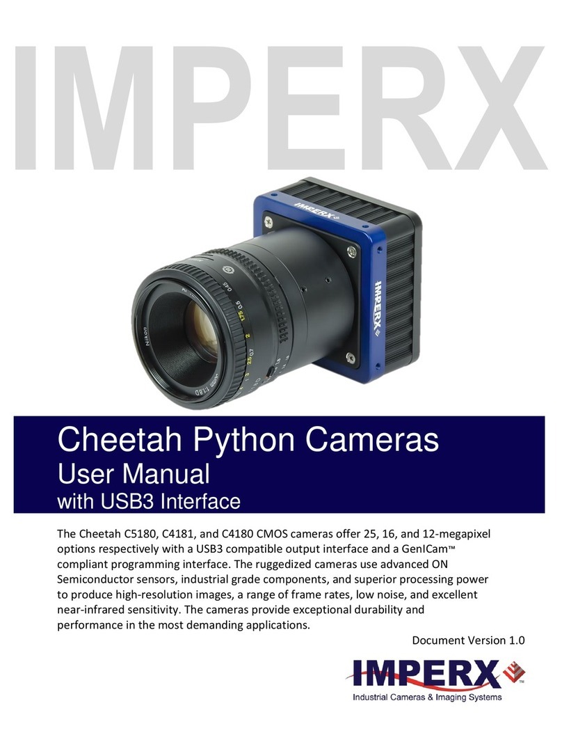
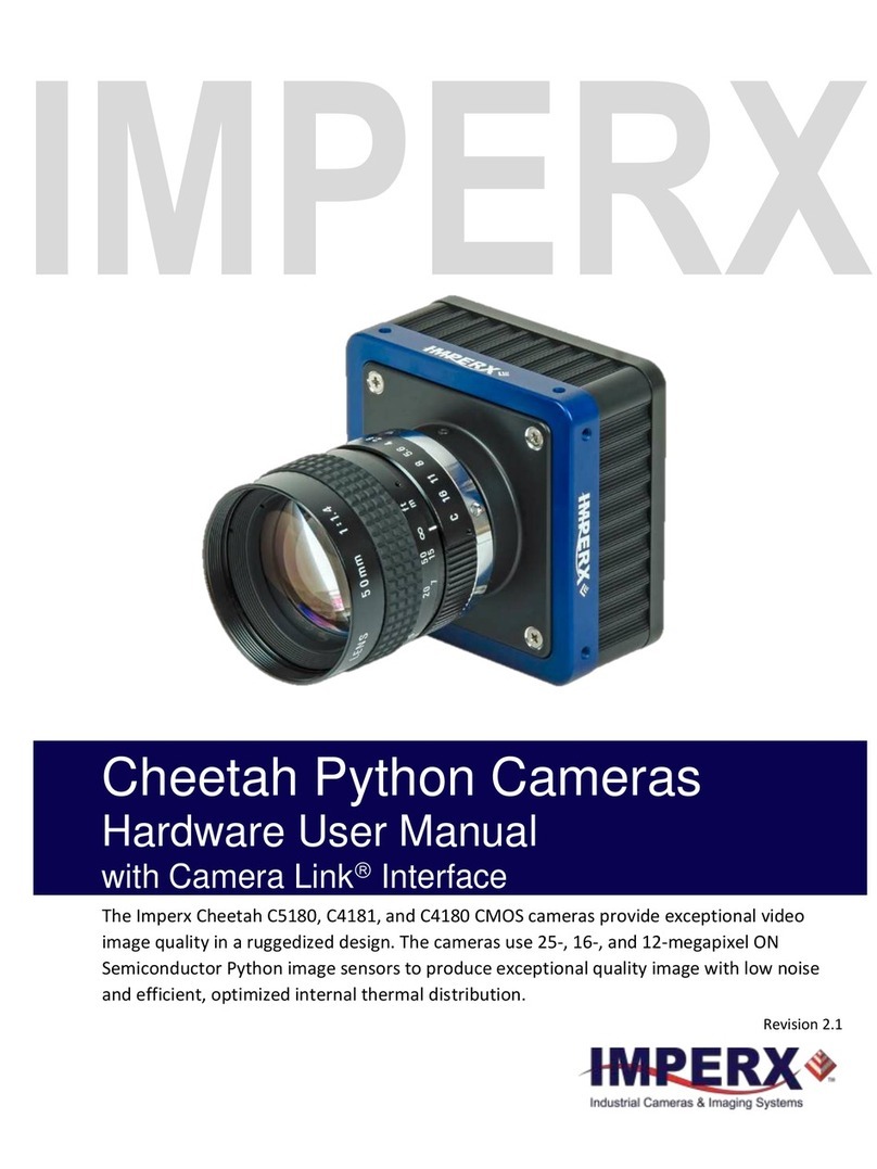
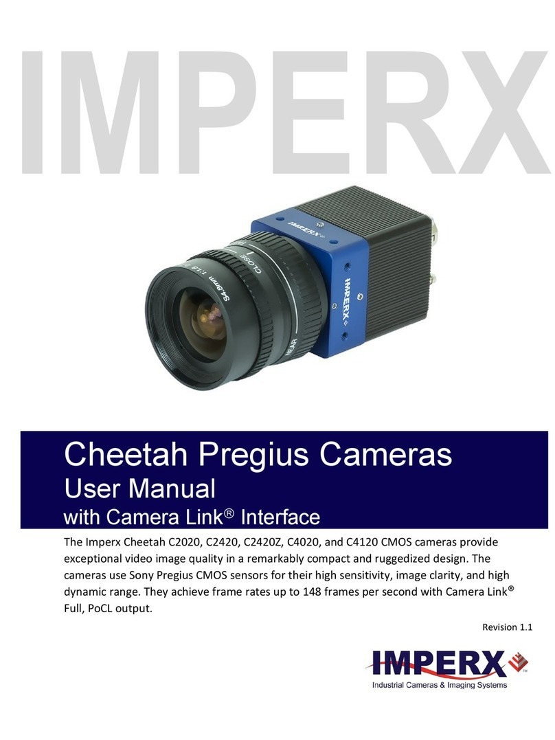
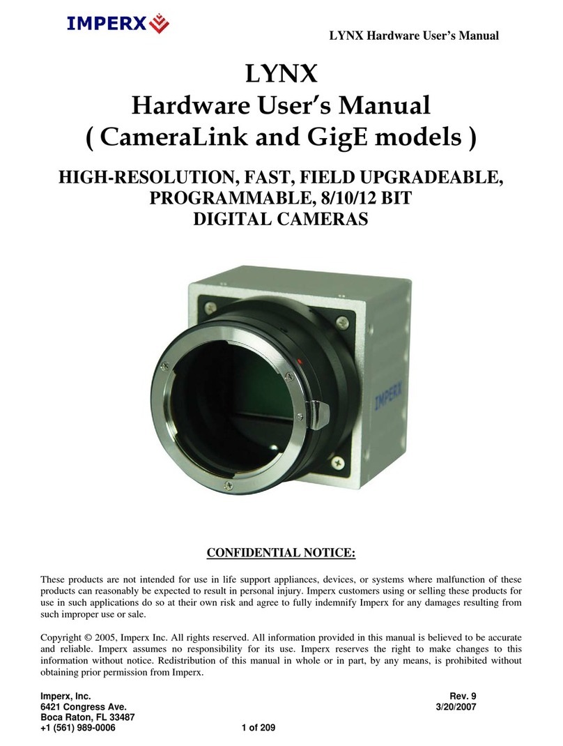
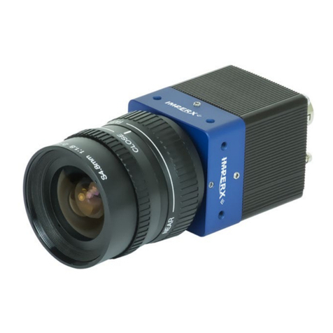
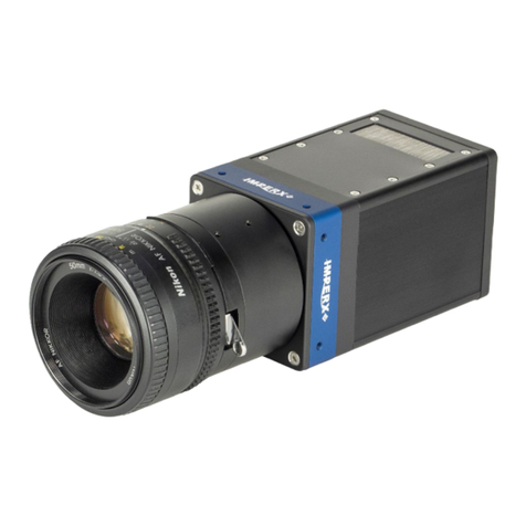
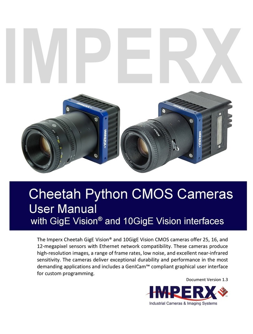
Imperx Cheetah Pregius Series User manual

IMPERX
Cheetah Pregius Cameras
User Manual
with GigE VisionInterface
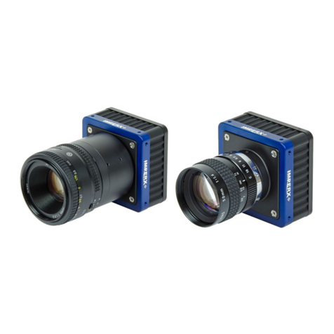
The Imperx Cheetah CMOS cameras provide exceptional video image quality in a
remarkably compact and ruggedized design with resolutions from 3 to 31 MP. The cameras
use Sony 2nd and 3rd generation Pregius CMOS sensors for their high sensitivity, image
clarity, and high dynamic range. They achieve frame rates up to 35 frames per second with
GigE Vision®output interface and support power over ethernet (PoE).
Revision 1.0

Cheetah Pregius Camera with GigE Vision®Interface – User Manual
August 27, 2019 Page 2 of 123 Rev 1.0
About Imperx, Inc.
IMPERX, Inc. is a leading designer and manufacturer of high performance, high quality digital
cameras, frame grabbers, and accessories for industrial, commercial, military, and aerospace
imaging applications including flat panel inspection, biometrics, aerial mapping, surveillance,
traffic management, semiconductors and electronics, scientific & medical Imaging, printing,
homeland security, space exploration, and other imaging and machine vision applications.
Fortune 100 companies, federal and state government agencies, domestic and foreign
defense agencies, academic institutions, and other customers worldwide use IMPERX
products.
Imperx, Inc. | 6421 Congress Ave. | Boca Raton, FL, 33487
US Phone: +1 (561) 989-0006

Cheetah Pregius Camera with GigE Vision®Interface – User Manual
August 27, 2019 Page 3 of 123 Rev 1.0
Warranty
IMPERX warrants performance of its products and related software to the specifications
applicable at the time of sale in accordance with IMPERX’s standard warranty, which is 2 (two)
years parts and labor.
Do not open the housing of the camera. Warranty voids if the housing has been open or
tampered.
IMPORTANT NOTICE
This camera has been tested and complies with the limits of Class A digital device, pursuant
to part 15 of the FCC rules.
Copyright © 2019 IMPERX Inc. All rights reserved. All information provided in this manual is
believed to be accurate and reliable. No responsibility is assumed by IMPERX for its use.
IMPERX reserves the right to make changes to this information without notice. Redistribution
of this manual in whole or in part, by any means, is prohibited without obtaining prior
permission from IMPERX. IMPERX reserves the right to make changes to its products or to
discontinue any product or service without notice and advises its customers to obtain the
latest version of relevant information to verify, before placing orders, that the information
being relied on is current.
IMPERX PRODUCTS ARE NOT DESIGNED, INTENDED, AUTHORIZED, OR WARRANTED TO BE
SUITABLE FOR USE IN LIFE-SUPPORT APPLICATIONS, DEVICES OR SYSTEMS OR OTHER CRITICAL
APPLICATIONS, WHERE MALFUNCTION OF THESE PRODUCTS CAN REASONABLY BE EXPECTED
TO RESULT IN PERSONAL INJURY. IMPERX CUSTOMERS USING OR SELLING THESE PRODUCTS
FOR USE IN SUCH APPLICATIONS DO SO AT THEIR OWN RISK AND AGREE TO FULLY INDEMNIFY
IMPERX FOR ANY DAMAGES RESULTING FROM SUCH IMPROPER USE OR SALE.

Cheetah Pregius Camera with GigE Vision®Interface – User Manual
August 27, 2019 Page 4 of 123 Rev 1.0
TABLE OF CONTENTS
1About the Camera........................................................................... 11
1.1 General .....................................................................................................................11
Key Features ....................................................................................................12
1.2 Technical Specifications ...........................................................................................13
C2000 and C2400 Cameras Specifications.......................................................13
C2010 and C2410 Cameras Specifications.......................................................14
C3210 and C4010 Cameras Specifications.......................................................15
C4110 Camera Specifications ..........................................................................16
C2410Y/Z and C4110Y/Z Cameras Specifications ............................................17
C4410 and C5410 Cameras Specifications.......................................................18
C6410 Camera Specifications ..........................................................................19
1.3 Ordering Information ...............................................................................................20
1.4 Technical Support.....................................................................................................21
2Hardware........................................................................................22
2.1 C2000 and C2400 Cameras Connectivity .................................................................22
Pin Assignment ................................................................................................23
2.2 C2010, C2410, C3210, C4010 and C4110 Cameras Connectivity .............................24
Pin Assignments...............................................................................................25
2.3 C4410, C5410, C6410 Cameras Connectivity ...........................................................26
Pin Assignments...............................................................................................26
2.4 P67 Cameras Connectivity........................................................................................27
Power and I/O Connector Pin Assignments.....................................................28
Ethernet Connector Pin Assignment ...............................................................29
2.5 Camera LED Status Indicator....................................................................................30
2.6 POE and External Power Supply...............................................................................30
PS12V04A Standard Power Supply ..................................................................31
Power and I/O cable CBL-COM01....................................................................32
I/O Cable PWIO01............................................................................................33
Active Canon EF mount ...................................................................................34
2.7 Electrical Connectivity ..............................................................................................34
Opto-isolated Input .........................................................................................35
TTL/LVTTL Input...............................................................................................35
TTL Output.......................................................................................................35
Opto-isolated Output ......................................................................................36
2.8 Mechanical Drawings ...............................................................................................38
C2000 and C2400 Cameras..............................................................................38
C2010, C2410, C3210, C4010, and C4110 Cameras.........................................40
C4410, C5410, and C6410 Cameras.................................................................42
P67 Cheetah Cameras......................................................................................44
2.9 Optical ......................................................................................................................46
P67 Cameras Lens Tubes .................................................................................47
2.10 Environmental........................................................................................................47
3GenICamTM API Module – Configuring the Camera........................... 48
3.1 Overview ..................................................................................................................48
3.2 Camera User Set Description ...................................................................................48
Startup Procedure ...........................................................................................48
3.3 GenApi Camera Configuration .................................................................................48
Device Control .................................................................................................49

Cheetah Pregius Camera with GigE Vision®Interface – User Manual
August 27, 2019 Page 5 of 123 Rev 1.0
Version Information ........................................................................................50
Image Format Control .....................................................................................52
Acquisition Control ..........................................................................................54
Gain Control.....................................................................................................56
Auto Exposure and Auto Gain Control (AEC/AGC) ..........................................57
Data Correction ...............................................................................................59
White Balance..................................................................................................60
Output and Strobe Signals...............................................................................61
Pulse Generator.............................................................................................62
Canon Lens Control .......................................................................................63
Transport Layer Information .........................................................................65
User Set Controls...........................................................................................68
Event Control.................................................................................................69
4Software GUI .................................................................................. 70
4.1 Overview ..................................................................................................................70
Supported Operating Systems.........................................................................70
Compatibility ...................................................................................................71
User Interface and Functionality .....................................................................71
4.2 Installing the Software .............................................................................................71
Installation.......................................................................................................71
4.3 Camera SDK ..............................................................................................................75
4.4 Connecting to Cameras ............................................................................................76
4.5 Using the IpxPlayer...................................................................................................78
Menu Bar .........................................................................................................78
4.6 Saving and Loading Configurations ..........................................................................79
4.7 Camera parameter Panel .........................................................................................80
Device Control .................................................................................................80
Version Info Controls.......................................................................................81
Image Format Controls....................................................................................82
Acquisition Control ..........................................................................................84
Gain Controls ...................................................................................................86
Auto Gain and Auto Exposure .........................................................................87
Data Correction Controls.................................................................................89
White Balance Controls ...................................................................................90
Strobe Controls................................................................................................91
Pulse Generator Controls ..............................................................................92
Canon Lens Control .......................................................................................92
Transport Layer Control.................................................................................95
User Set Controls...........................................................................................97
Event Control.................................................................................................97
4.8 Capture Panel...........................................................................................................98
Recording Acquired Images.............................................................................98
Saving Image Output .......................................................................................98
4.9 Log Panel ..................................................................................................................99
Channels to Log ...............................................................................................99
4.10 Statistics Panel .....................................................................................................100
5Camera Features........................................................................... 101
5.1 Exposure Control....................................................................................................101
Internal Exposure Control - Electronic Shutter..............................................101
5.2 Automatic Exposure Control ..................................................................................102

Cheetah Pregius Camera with GigE Vision®Interface – User Manual
August 27, 2019 Page 6 of 123 Rev 1.0
5.3 Automatic Gain Control..........................................................................................103
5.4 Acquisition Control.................................................................................................103
5.5 Video Amplifier Gain and Offset ............................................................................104
Digital gain .....................................................................................................104
Digital Offset..................................................................................................104
Black Level Auto-calibration and Offset ........................................................104
5.6 Data Output Format...............................................................................................105
Pixel Format...................................................................................................105
5.7 Pulse Generator .....................................................................................................105
5.8 Input / Output Control ...........................................................................................106
5.9 Camera Triggering ..................................................................................................106
Trigger Modes................................................................................................106
Trigger Sources ..............................................................................................106
5.10 Strobe and Synchronization Controls...................................................................107
5.11 Area of Interest ....................................................................................................108
Horizontal and Vertical Window .................................................................108
Factors Impacting Frame Rate.....................................................................108
Slave AOI......................................................................................................109
5.12 Gamma Control ....................................................................................................109
5.13 Bad Pixel Correction .............................................................................................109
Static Pixel Correction .................................................................................110
Dynamic Pixel Correction ............................................................................110
5.14 Flat Field Correction .............................................................................................110
5.15 Test Image Pattern ...............................................................................................110
5.16 Color Control ........................................................................................................111
5.17 Configuration Memory.........................................................................................112
6Image Sensor Technology.............................................................. 113
6.1 General Information...............................................................................................113
6.2 Spectral Sensitivity .................................................................................................114
6.3 Micro-polarized Cameras .......................................................................................114
Appendix A – Spectral Response ............................................................ 115
A.1 Cheetah C2000 and C2010 Spectral Response..........................................................115
A.2 Cheetah C2400 and C2410 Spectral Response..........................................................116
A.3 Cheetah C2410Y/Z Spectral Response.......................................................................117
A.4 Cheetah C3210 Spectral Response............................................................................118
A.5 Cheetah C4010 Spectral Response............................................................................119
A.6 Cheetah C4110 Spectral Response............................................................................120
A.7 Cheetah C4410 Spectral Response............................................................................121
A.8 Cheetah C5410 Spectral Response............................................................................122
A.9 Cheetah C6410 Spectral Response............................................................................123

Cheetah Pregius Camera with GigE Vision®Interface – User Manual
August 27, 2019 Page 7 of 123 Rev 1.0
LIST OF TABLES
Table 1: Cheetah cameras with GigE Vision® PoE interface....................................................12
Table 2: C2000 and C2400 Cameras Specifications.................................................................13
Table 3: C2010 and C2410 Cameras Specifications.................................................................14
Table 4: C3210 and C4010 Cameras Specifications.................................................................15
Table 5: C4110 Camera Specifications ....................................................................................16
Table 6: C2410Y/Z and C4110Y/Z Cameras Specifications ......................................................17
Table 7: C4410 and C5410 Cameras Specifications.................................................................18
Table 8: C6410 Camera Specifications ....................................................................................19
Table 9: Cheetah Camera Ordering Codes ..............................................................................20
Table 10: 6-pin Hirose Connector Pin Mapping ......................................................................23
Table 11: 12-pin Hirose Connector Pin Mapping ....................................................................25
Table 12: 8-pin BULGIN Connector Pin Mapping ....................................................................28
Table 13: MACOM Connector Pin Mapping............................................................................29
Table 14: LED status Indicator Descriptions............................................................................30
Table 15: Inputs and outputs of the Cheetah Cameras ..........................................................34
Table 16: Cheetah Cameras’ Adapters and Back Focal Distances...........................................46
Table 17: Lens tube specifications ..........................................................................................47
Table 18: Parameters availability............................................................................................49
Table 19: Device Control parameters......................................................................................49
Table 20: Version Information parameters.............................................................................50
Table 21: Image Format Control parameters..........................................................................52
Table 22: Slave AOI parameters ..............................................................................................53
Table 23: Acquisition Control parameters ..............................................................................54
Table 24: Gain Control parameters.........................................................................................56
Table 25: Auto Exposure and Auto Gain Control parameters.................................................57
Table 26: Status parameters ...................................................................................................58
Table 27: Data Correction parameters....................................................................................59
Table 28: White Balance parameters ......................................................................................60
Table 29: OUT1 parameters ....................................................................................................61
Table 30: OUT2 parameters (some cameras may not support OUT2)....................................61
Table 31: Strobe 1 and Strobe2 parameters (some cameras may not support Strobe2) .......62
Table 32: Pulse Generator parameters ...................................................................................62
Table 33: General Canon Lens Control parameters ................................................................63
Table 34: Controller Settings...................................................................................................63
Table 35: Focus parameters ....................................................................................................64
Table 36: Iris parameters ........................................................................................................64
Table 37: PayLoadSize parameter ...........................................................................................65
Table 38: GigE Vision parameters ...........................................................................................65
Table 39: User Set Controls parameters .................................................................................68
Table 40: Event Control parameters .......................................................................................69
Table 41: Acquisition Control modes ....................................................................................103
Table 42: Output signals........................................................................................................107
Table 43: Slave AOI modes....................................................................................................109
Table 44: Test patterns .........................................................................................................110
Table 45: Automatic white balance modes...........................................................................111

Cheetah Pregius Camera with GigE Vision®Interface – User Manual
August 27, 2019 Page 8 of 123 Rev 1.0
LIST OF FIGURES
Figure 1: POE-C2000 and POE-C2400 camera back panel connectors....................................22
Figure 2: 6-pin Hirose Connector Pin-outs (C2000 and C2400 cameras) ................................23
Figure 3: POE-C2010, POE-C2410, POE-C3210, POE-C4010, and POE-C4110 camera back
panel connectors.....................................................................................................................24
Figure 4: 12-pin Hirose Connector Pin-outs (POE-C2010, POE-C2410, POE-C3210, POE-
C4010, POE-C4110, POE-C4410, POE-C5410, and POE-C6410 cameras) ................................25
Figure 5: POE-C4410, POE-C5410, and POE-C6410 camera back panel connectors...............26
Figure 6: P67-C2010, P67-C2410, P67-C3210, P67-C4010, and P67-C4110 camera back panel
connectors...............................................................................................................................27
Figure 7: BULGIN PXMBNI12RPM08APCM12 connector pin-outs (P67-C2010, P67-C2410,
P67-C3210, P67-C4010, and P67-C4110 cameras)..................................................................28
Figure 8: MACOM MMT361A315 connector pin-outs (P67-C2010, P67-C2410, P67-C3210,
P67-C4010, and P67-C4110 cameras) .....................................................................................29
Figure 9: PS12V04A power supply (ordered separately) ........................................................31
Figure 10: CBL-COM01 cable for use with C2000 and C2400 cameras (ordered separately) .32
Figure 11: CBL-PWIO01 cable (ordered separately)................................................................33
Figure 12: The camera (left) and Canon EF lens mount (center) connect internally ..............34
Figure 13: Opto-isolated input electrical schematic (simplified) ............................................35
Figure 14: TTL input electrical schematic (simplified).............................................................35
Figure 15: TTL output electrical schematic (simplified) ..........................................................35
Figure 16: Out2 Open drain logic driver circuit.......................................................................36
Figure 17: Out 2 Low side load driver circuit...........................................................................36
Figure 18: Out2 High side load driver circuit...........................................................................37
Figure 19: POE-C2000 and POE-C2400 cameras .....................................................................38
Figure 20: Front and Back Views of the POE-C2000 and POE-C2400 cameras .......................38
Figure 21: Bottom and Side views of the POE-C2000 and POE-C2400 cameras .....................39
Figure 22: POE-C2010, POE-C2410, POE-C2410Y/Z, POE-C3210, POE-C4010, POE-C4110, POE-
C4110Y/Z camera ....................................................................................................................40
Figure 23: Front and Back Views of the POE-C2010, POE-C2410, POE-C2410Y/Z, POE-C3210,
POE-C4010, POE-C4110, and POE-C4110Y/Z cameras ............................................................40
Figure 24: Top and Side views of the POE-C2010, POE-C2410, POE-C2410Y/Z, POE-C3210,
POE-C4010, POE-C4110, and POE-C4110Y/Z cameras ............................................................41
Figure 25: POE-C4410, POE-C5410, POE-C6410 cameras .......................................................42
Figure 26: Front and Back views of the POE-C4410, POE-C5410, and POE-C6410 cameras ...42
Figure 27: Top and Side views of the POE-C4410, POE-C5410, and POE-C6410 cameras ......43
Figure 28: P67-C2010, P67-C2410, P67-C3210, P67-C4010, P67-C4110 cameras ..................44
Figure 29: Front and Back views of the P67-C2010, P67-C2410, P67-C3210, P67-C4010, P67-
C4110 cameras ........................................................................................................................44
Figure 30: Mechanical drawings of the P67-C2010, P67-C2410, P67-C3210, P67-C4010, P67-
C4110 cameras ........................................................................................................................45
Figure 31: IpxPlayer graphical user interface..........................................................................70
Figure 32: Security screen .......................................................................................................71
Figure 33: Welcome Setup screen ..........................................................................................72
Figure 34: License Agreement screen .....................................................................................72
Figure 35: Choose Components screen...................................................................................73
Figure 36 Choose Install Location screen................................................................................73
Figure 37: Uninstall any existing versions dialog ....................................................................73
Figure 38: Installation Complete screen .................................................................................74
Figure 39: Completing Imperx Camera SDK Setup screen ......................................................74
Figure 40: IpxPlayer Icon .........................................................................................................74
Cheetah Pregius Camera with GigE Vision®Interface – User Manual
August 27, 2019 Page 9 of 123 Rev 1.0
Figure 41: Imperx Camera SDK file locations on your computer ............................................75
Figure 42: Connecting to a camera .........................................................................................76
Figure 43: Select Camera dialogue..........................................................................................76
Figure 44: Access status showing IP Subnet Mismatch...........................................................77
Figure 45: Select an access level .............................................................................................80
Figure 46: Device control parameters.....................................................................................80
Figure 47: Version info parameters.........................................................................................81
Figure 48: Image format control parameters..........................................................................82
Figure 49: Slave AOI parameters.............................................................................................83
Figure 50: Acquisition control parameters..............................................................................84
Figure 51: Gain Control ...........................................................................................................86
Figure 52: Auto Gain and Auto Exposure................................................................................87
Figure 53: Data correction parameters...................................................................................89
Figure 54: White balance parameters.....................................................................................90
Figure 55: Strobe parameters .................................................................................................91
Figure 56: Pulse generator parameters...................................................................................92
Figure 57: Canon lens control general parameters.................................................................92
Figure 58: Canon lens control – Controller settings................................................................93
Figure 59: Canon lens control – Focus settings.......................................................................93
Figure 60: Canon lens control – Iris settings ...........................................................................94
Figure 61: Transport layer control ..........................................................................................95
Figure 62: User set parameters...............................................................................................97
Figure 63: Event Control parameters ......................................................................................97
Figure 64: The Capture panel saves images and video ...........................................................98
Figure 65: The Log panel records data transfers.....................................................................99
Figure 66: Statistics panel .....................................................................................................100
Figure 67: Global Shutter with 8.33mS exposure time .........................................................102
Figure 68: 12-bit internal Digitization with 12-bit, 10-bit, and 8-bit outputs........................105
Figure 69: Internal pulse generator ......................................................................................105
Figure 70: Horizontal and vertical window positioning ........................................................108
Figure 71: The POE-C2410Y/Z and POE-C4110Y/Z cameras micro-polarizer blocks image
obscuring light waves from reaching the sensor...................................................................114
Figure 72: Cheetah C2000 and C2010 Color Spectral Response ...........................................115
Figure 73: Cheetah C2000 and C2010 Monochrome Spectral Response..............................115
Figure 74: Cheetah C2400 and C2410 Color Spectral Response ...........................................116
Figure 75: Cheetah C2400 and C2410 Monochrome Spectral Response..............................116
Figure 76: Cheetah C2410Y/Z Color Spectral Response ........................................................117
Figure 77: Cheetah C2410Y/Z Monochrome Spectral Response ..........................................117
Figure 78: Cheetah C3210 Color Spectral Response .............................................................118
Figure 79: Cheetah C3210 Monochrome Spectral Response................................................118
Figure 80: Cheetah C4010 Color Spectral Response .............................................................119
Figure 81: Cheetah C4010 Monochrome Spectral Response................................................119
Figure 82: Cheetah C4110 Color Spectral Response .............................................................120
Figure 83: Cheetah C4110 Monochrome Spectral Response................................................120
Figure 84: Cheetah C4410 Color Spectral Response .............................................................121
Figure 85: Cheetah C4410 Monochrome Spectral Response................................................121
Figure 86: Cheetah C5410 Color Spectral Response .............................................................122
Figure 87: Cheetah C5410 Monochrome Spectral Response................................................122
Figure 88: Cheetah C6410 Color Spectral Response .............................................................123
Figure 89: Cheetah C6410 Monochrome Spectral Response................................................123

Cheetah Pregius Camera with GigE Vision®Interface – User Manual
August 27, 2019 Page 10 of 123 Rev 1.0
REVISION HISTORY
Revision
Date
Reviser
Comments
1.0
8/27/2019
K. Wetzel
I. Barabanova
Initial release.

Cheetah Pregius Camera with GigE Vision®Interface – User Manual
August 27, 2019 Page 11 of 123 Rev 1.0
1 About the Camera
1.1 General
The GigE Vision® with Power over Ethernet (PoE) Cheetah CMOS cameras are built around
advanced Sony Pregius CMOS image sensors with global shutter for high quality images in a
small ruggedized form factor. Cheetah cameras are progressive scan digital cameras featuring
a built-in image-processing engine, low power consumption, low noise, and high dynamic
range (71 dB). The cameras provide several trigger modes and output strobes allowing you to
synchronize the image capture of one or more cameras to an external event. They also provide
an Area of Interest (AOI), programmable look-up tables (LUT) and the ability to store up to
four different camera configurations. Using the simple GenICam™ compliant user interface,
you can quickly apply image corrections to enhance recognition or quality.
The cameras are suitable for a wide range of environmental conditions and applications, such
as machine vision, industrial inspection, surveillance, aerospace, and more.
The C2000 and C2400 cameras are ultra-compact with a slimmed down feature set for cost-
sensitive applications.
The C3210 camera has large 4.5-micron square pixels for improved sensitivity and dynamic
range.
The Cheetah P67 cameras feature IP67-rated enclosure that protects a camera from ingress
of water, dirt, dust, sand and other contaminants and can be utilized in harsh environments.
Imperx offers IP67 lens tubes of different diameters to be used with varying lens sizes to suit
your specific requirements.
The C4410, C5410, and C6410 cameras feature 20 MP, 17 MP, and 31 MP Sony Pregius CMOS
sensors respectively, provide support for active Canon EOS lens with iris and focus controls,
and are available with optional thermal cooling that lowers the sensor temperature to a
certain level reducing thermal noise.
The C2410Y/Z and C4110Y/Z cameras feature a micro-polarized Sony Pregius CMOS sensors.
The sensors have a 2x2 pixel sub-array where each pixel within the sub-array blocks a different
polarization angle (0, 45, 90 or 135 degrees).
The cameras ship with the Imperx SDK and IpxPlayer for playing/recording videos and setting
camera features.
Table 1enlists the Cheetah CMOS camera models featuring GigE Vision® with PoE interface.
The cameras use global shutter operation for superior motion capture with exceptionally high
frame rates for high throughput applications. You can synchronize the cameras to an external
trigger source and vary exposure times using internal controls or an external pulse width. An
Area of Interest (AOI) can be programmed for each acquisition frame.
Built-in gamma correction and user-defined look-up table (LUT) capabilities optimize the
camera’s dynamic range features. Bad pixel correction is used for pixels that are over-
responding or under-responding. Auto White Balance (AWB) is available in color cameras to
correct for color temperature.

Cheetah Pregius Camera with GigE Vision®Interface – User Manual
August 27, 2019 Page 12 of 123 Rev 1.0
Table 1: Cheetah cameras with GigE Vision® PoE interface
Camera
Model
Resolution
(MP)
Resolution
(H x V)
Frame
Rate
(Max)
Type
(Color/
Mono)
Optical
format
Pixel Size
(microns)
Sony Sensor
Model
POE-C2000
3
2064 x 1544
36
C, M
1/1.8”
3.45
IMX265
POE-C2010
3
2064 x 1544
36
C, M
1/1.8”
3.45
IMX265
P67-C2010
3
2064 x 1544
36
C, M
1/1.8”
3.45
IMX265
POE-C2400
5
2464 x 2056
22
C, M
2/3”
3.45
IMX264
POE-C2410
5
2464 x 2056
22
C, M
2/3”
3.45
IMX264
POE-C2410Y/Z
5
2464 x 2056
22
Y, Z
2/3”
3.45
IMX250MY/ZR
P67-C2410
5
2464 x 2056
22
C, M
2/3”
3.45
IMX264
POE-C3210
7
3216 x 2208
16
C, M
1.1”
4.5
IMX428
P67-C3210
7
3216 x 2208
16
C, M
1.1”
4.5
IMX428
POE-C4010
9
4112 x 2176
13
C, M
1”
3.45
IMX267
P67-C4010
9
4112 x 2176
13
C, M
1”
3.45
IMX267
POE-C4110
12
4112 x 3008
9
C, M
1.1”
3.45
IMX304
POE-C4110Y/Z
12
4112 x 3008
9
Y, Z
1.1”
3.45
IMX253MY/ZR
P67-C4110
12
4112 x 3008
9
C, M
1.1”
3.45
IMX304
POE-C4410
20
4432 x 4436
6
C, M
4/3”
3.45
IMX367
POE-C5410
17
5472 x 3084
7
C, M
4/3”
3.45
IMX387
POE-C6410
31
6464 x 4852
3.7
C, M
APS-C
3.45
IMX342
Key Features
•Global shutter (GS)
•Color and monochrome versions
•Fast frame rates
•High data transfer rates up to 1000 megabits per second (or 1Gbit/s)
•Uses CAT5e or CAT6 cables and standard RJ45 connectors (exception: P67 cameras)
•Data transfer up to 100 meters in length
•Internal, external exposure controls
•Automatic exposure and gain control (AEC/AGC) (exception: C2000 and C2400)
•Analog and digital gain control
•Offset control
•Built-in pulse generator
•Area of interest (AOI)
•Programmable external inputs and outputs
•Multiple Trigger/Synchronization options
•Automatic and manual white balance
•Four 12-bit look-up tables (LUT)
•Bad pixel correction, user-defined and factory
•Flat field correction, user defined and factory (exception: C2000 and C2010)
•Dynamic transfer function and gamma corrections
•Optional P-Iris (exception: C4410, C5410, C6410, C2000, C2400, and P67 cameras)
•Canon EOS EF lens control (C4410, C5410, C6410 cameras only)
•Temperature monitor
•Field upgradeable firmware

Cheetah Pregius Camera with GigE Vision®Interface – User Manual
August 27, 2019 Page 13 of 123 Rev 1.0
1.2 Technical Specifications
C2000 and C2400 Cameras Specifications
Table 2: C2000 and C2400 Cameras Specifications
Specifications
C2000 – 3 MP
C2400 – 5 MP
Active image resolution
2064 (H) x 1544 (V)
2464 (H) x 2056 (V)
Pixel size
3.45 µm
3.45 µm
Optical format
1/1.8 inch
2/3 inch
Shutter
Global
Global
Frame rate (max)
36 (8-bit), 18 (10-, 12-bit unpacked), 24
(10-, 12-bit packed)
22 (8-bit), 11 (10-, 12-bit unpacked), 15 (10-
, 12-bit packed)
Sensor digitization
12-bit
12-bit
Dynamic range
71 dB
71 dB
Output bit depth
8, 10, or 12-bit
8, 10, or 12-bit
Shutter speed
1 µs/step, 14 µs to 16.0 s
Analog / Digital gain
0-48 dB (0.1 dB step)
Digital gain
1x (0 dB) to 4x (12 dB), 0.001x step
Black level offset
Manual (0-255), auto
Exposure control
Manual, external, off
White balance
Once, manual, auto, off
Area of Interest (AOI)
One
One
Trigger inputs
External, pulse generator, software
Trigger options
Edge, pulse width, trigger filter, trigger
delay, debounce
Edge, pulse width, trigger filter, trigger
delay, debounce
Trigger modes
Free-run, standard, fast
I/O control
1 IN (OPTO) / 1 OUT (OPTO)
Strobe output
1 strobe, programmable position and
duration
1 strobe, programmable position and
duration
Pulse generator
Yes, programmable
Yes, programmable
Lens mount
C-mount (default)
C-mount (default)
Camera housing
6000 series aluminum
Upgradeable firmware
Yes
Yes
Data correction
4 LUTs - pre-programmed with Gamma
0.45, bad pixel correction (static,
dynamic)
4 LUTs- pre-programmed with Gamma
0.45, flat field correction
bad pixel correction (static, dynamic)
Supply voltage range
12 VDC (6 V – 30 V), 1.5 A inrush @ 12 V;
PoE (IEEE 802.3at)
12 VDC (6 V – 30 V), 1.5 A inrush @ 12 V;
PoE (IEEE 802.3at)
Power consumption
Typical: 3.72 W @ 12 V; PoE: 5 W
Typical: 3.48 W @ 12 V; PoE: 4.96 W
Camera size (W x H x L)
(29 x 29 x 59.4) mm
(29 x 29 x 59.4) mm
Weight
77.6 grams
77.6 grams
Vibration, shock
30G (20-200 Hz XYZ) / 500G
Environmental
-30 °C to +70 °C Operating;
-40 °C to +85 °C Storage
-30 °C to +70 °C Operating;
-40 °C to +85 °C Storage
Relative humidity
10% to 90% non-condensing
Regulatory
FCC part 15, CE, RoHS

Cheetah Pregius Camera with GigE Vision®Interface – User Manual
August 27, 2019 Page 14 of 123 Rev 1.0
C2010 and C2410 Cameras Specifications
Table 3: C2010 and C2410 Cameras Specifications
Specifications
POE-C2010, P67-C2010 – 3 MP
POE-C2410, P67-C2410 – 5 MP
Active image resolution
2064 (H) x 1544 (V)
2464 (H) x 2056 (V)
Pixel size
3.45 µm
3.45 µm
Optical format
1/1.8 inch
2/3 inch
Shutter
Global
Global
Frame rate (max)
36 (8-bit), 18 (10,12-bit unpacked), 24
(10,12-bit packed)
22 (8-bit), 11 (10,12-bit unpacked), 15
(10,12-bit packed)
Sensor digitization
12-bit
12-bit
Dynamic range
71 dB
71 dB
Output bit depth
8, 10, or 12-bit
8, 10, or 12-bit
Shutter speed
1 µs/step, 14 µs to 16.0 s
Analog / Digital gain
Manual, auto; 0-48 dB (0.1 dB step)
Digital gain
1x (0 dB) to 4x (12 dB), 0.001x step
AEC/AGC
Yes
Yes
Black level offset
Manual (0-255), auto
Exposure control
Manual, auto, external, off
White balance
Once, manual, auto, off
Area of Interest (AOI)
Two
Two
Trigger inputs
External, pulse generator, software
Trigger options
Edge, pulse width, trigger filter, trigger
delay, debounce
Edge, pulse width, trigger filter, trigger
delay, debounce
Trigger modes
Free-run, standard, fast
I/O control
POE
2 IN (OPTO, LVTTL) / 2 OUT (OPTO, TTL)
P67
1 IN (OPTO) / 2 OUT (OPTO, TTL)
Strobe output
2 strobes, programmable position and
duration
2 strobes, programmable position and
duration
Pulse generator
Yes, programmable
Yes, programmable
Lens mount
POE
C-mount (default), P-Iris (optional)
P67
C-mount (default)
C-mount (default)
Camera housing
6000 series aluminum
Upgradeable firmware
Yes
Yes
Data correction
4 LUTs - pre-programmed with Gamma
0.45, bad pixel correction (static,
dynamic)
4 LUTs pre-programmed with Gamma 0.45,
flat field correction, bad pixel correction
(static, dynamic)
Supply voltage range
12 VDC (6 V – 30 V), 1.5 A inrush @ 12 V;
PoE (IEEE 802.3at)
12 VDC (6 V – 30 V), 1.5 A inrush @ 12 V;
PoE (IEEE 802.3at)
Power consumption
Typical: 3 W @ 12 V; PoE: 4.64 W
Typical: 3.24 W @ 12 V; PoE: 4.69 W
Camera size
(W x H x L)
POE
(37 x 37 x 61.5) mm
(37 x 37 x 61.5) mm
P67
(48.5 x 42 x 61) mm (without lens tube)
Weight
POE
113.2 grams
113.2 grams
P67
196 grams (without lens tube)
Vibration, shock
20G (20-200 Hz XYZ) / 100G
Environmental
Operating
Storage
-30 °C to +75 °C (-40 °C to +85 °C tested)
-40 °C to +85 °C
-30 °C to +75 °C (-40 °C to +85 °C tested)
-40 °C to +85 °C
Relative humidity
10% to 90% non-condensing
Regulatory
FCC part 15, CE, RoHS

Cheetah Pregius Camera with GigE Vision®Interface – User Manual
August 27, 2019 Page 15 of 123 Rev 1.0
C3210 and C4010 Cameras Specifications
Table 4: C3210 and C4010 Cameras Specifications
Specifications
POE-C3210, P67-C3210 – 7.1 MP
POE-C4010, P67-C4010 – 9 MP
Active image resolution
3216 (H) x 2208 (V)
4112 (H) x 2176 (V)
Pixel size
4.5 µm
3.45 µm
Optical format
1.1 inch
1 inch
Shutter
Global
Global
Frame rate (max)
16 fps (8-bit), 8 fps (10,12-bit unpacked),
10 fps (10,12-bit packed)
13.2 fps (8-bit), 6.6 fps (10, 12-bit unpacked),
8.8 fps (10, 12-bit packed)
Sensor digitization
12-bit
12-bit
Dynamic range
77 dB
71 dB
Output bit depth
8, 10, or 12-bit
8, 10, or 12-bit
Shutter speed
1 µs/step, 5 µs to 16.0 s
1 µs/step, 14 µs to 16.0 s
Analog / Digital gain
Manual, auto; 0-48 dB (0.1 dB step)
Digital gain
1x (0 dB) to 4x (12 dB), 0.001x step
AEC/AGC
Yes
Yes
Black level offset
Manual (0-255), auto
Exposure control
Manual, auto, external, off
White balance
Once, manual, auto, off
Area of Interest (AOI)
Two
Two
Trigger Inputs
External, pulse generator, software
Trigger options
Edge, pulse width, trigger filter, trigger
delay, debounce
Edge, pulse width, trigger filter, trigger
delay, debounce
Trigger modes
Free-run, standard, fast
I/O control
POE
2 IN (OPTO, LVTTL) / 2 OUT (OPTO, TTL)
P67
1 IN (OPTO) / 2 OUT (OPTO, TTL)
Strobe output
2 strobes, programmable position and
duration
2 strobes, programmable position and
duration
Pulse generator
Yes, programmable
Yes, programmable
Lens mount
POE
C-mount (default), P-Iris (optional)
P67
C-mount (default)
C-mount (default)
Camera housing
6000 series aluminum
Upgradeable firmware
Yes
Yes
Data correction
4 LUTs- pre-programmed with Gamma
0.45, flat field correction, bad pixel
correction (static, dynamic)
4 LUTs- pre-programmed with Gamma
0.45, flat field correction, bad pixel
correction (static, dynamic)
Supply voltage range
12 VDC (6 V – 30 V), 1.5 A inrush @ 12 V;
PoE (IEEE 802.3at)
12 VDC (6 V – 30 V), 1.5 A inrush @ 12 V;
PoE (IEEE 802.3at)
Power consumption
Typical: 4.32 W @ 12 V; PoE: 5.95 W
Typical: 3.36 W @ 12 V; PoE: 4.91 W
Camera size
(W x H x L)
POE
(37 x 37 x 61.5) mm
(37 x 37 x 61.5) mm
P67
(48.5 x 42 x 61) mm (without lens tube)
Weight
POE
113.2 grams
113.2 grams
P67
196 grams (without lens tube)
Vibration, shock
20G (20-200 Hz XYZ) / 100G
Environmental
Operating
Storage
-30 °C to +75 °C (-40 °C to +85 °C tested)
-40 °C to +85 °C
-30 °C to +75 °C (-40 °C to +85 °C tested)
-40 °C to +85 °C
Relative humidity
10% to 90% non-condensing
Regulatory
FCC part 15, CE, RoHS

Cheetah Pregius Camera with GigE Vision®Interface – User Manual
August 27, 2019 Page 16 of 123 Rev 1.0
C4110 Camera Specifications
Table 5: C4110 Camera Specifications
Specifications
POE-C4110, P67-C4110 – 12 MP
Active image resolution
4112 (H) x 3008 (V)
Pixel size
3.45 µm
Optical format
1.1 inch
Shutter
Global
Frame rate (max)
9.6 fps (8-bit), 4.8 fps (10,12-bit unpacked),
6.4 fps (10,12-bit packed)
Sensor digitization
12-bit
Dynamic range
71 dB
Output bit depth
8, 10, or 12-bit
Shutter speed
1 µs/step, 14 µs to 16.0 s
Analog / Digital gain
Manual, auto; 0-48 dB (0.1 dB step)
Digital gain
1x (0 dB) to 4x (12 dB), 0.001x step
AEC/AGC
Yes
Black level offset
Manual (0-255), auto
Exposure control
Manual, auto, external, off
White balance
Once, manual, auto, off
Area of Interest (AOI)
Two
Trigger Inputs
External, pulse generator, software
Trigger options
Edge, pulse width, trigger filter, trigger delay, debounce
Trigger modes
Free-run, standard, fast
I/O control
POE
2 IN (OPTO, LVTTL) / 2 OUT (OPTO, TTL)
P67
1 IN (OPTO) / 2 OUT (OPTO, TTL)
Strobe output
2 strobes, programmable position and duration
Pulse generator
Yes, programmable
Lens mount
POE
C-mount (default), P-Iris (optional)
P67
C-mount (default)
Camera housing
6000 series aluminum
Upgradeable firmware
Yes
Data correction
4 LUTs- pre-programmed with Gamma 0.45, flat field correction, bad pixel
correction (static, dynamic)
Supply voltage range
12 VDC (6 V – 30 V), 1.5 A inrush @ 12 V; PoE (IEEE 802.3at)
Power
Typical: 3.48 W @ 12 V; PoE: 4.86 W
Camera size
(W x H x L)
POE
(37 x 37 x 61.5) mm
P67
(48.5 x 42 x 61) mm (without lens tube)
Weight
POE
113.2 grams
P67
196 grams (without lens tube)
Vibration, shock
20G (20-200 Hz XYZ) / 100G
Environmental
Operating
Storage
-30 °C to +75 °C (-40 °C to +85 °C tested)
-40 °C to +85 °C
Relative humidity
10% to 90% non-condensing
Regulatory
FCC part 15, CE, RoHS

Cheetah Pregius Camera with GigE Vision®Interface – User Manual
August 27, 2019 Page 17 of 123 Rev 1.0
C2410Y/Z and C4110Y/Z Cameras Specifications
Table 6: C2410Y/Z and C4110Y/Z Cameras Specifications
Specifications
POE-C2410Y/Z – 5 MP
POE-C4110Y/Z – 12 MP
Active image resolution
2464 (H) x 2056 (V)
1232 (H) x 1028 (V) per polarization angle
4112 (H) x 3008 (V)
2056 (H) x 1504 (V) per polarization angle
Pixel size
3.45 µm
3.45 µm
Optical format
2/3 inch
1.1 inch
Shutter
Global
Global
Frame rate (max)
22 (8-bit), 11 (10,12-bit unpacked), 15
(10,12-bit packed)
9.6 fps (8-bit), 4.8 fps (10,12-bit unpacked),
6.4 fps (10,12-bit packed)
Sensor digitization
12-bit
12-bit
Dynamic range
71 dB
71 dB
Output bit depth
8, 10, or 12-bit
8, 10, or 12-bit
Shutter speed
1 µs/step, 14 µs to 16.0 s
Analog / Digital gain
Manual, auto; 0-48 dB (0.1 dB step)
Digital gain
1x (0 dB) to 4x (12 dB), 0.001x step
AEC/AGC
Yes
Yes
Black level offset
Manual (0-255), auto
Exposure control
Manual, auto, external, off
White balance
Once, manual, auto, off
Polarization Angles
0, 45, 90, and 135 degrees
Area of Interest (AOI)
Two
Two
Trigger Inputs
External, pulse generator, software
Trigger options
Edge, pulse width, trigger filter, trigger
delay, debounce
Edge, pulse width, trigger filter, trigger
delay, debounce
Trigger modes
Free-run, standard, fast
I/O control
2 IN (OPTO, LVTTL) / 2 OUT (OPTO, TTL)
Strobe output
2 strobes, programmable position and
duration
2 strobes, programmable position and
duration
Pulse generator
Yes, programmable
Yes, programmable
Lens mount
C-mount (default), P-Iris (optional)
Camera housing
6000 series aluminum
Upgradeable firmware
Yes
Yes
Data correction
4 LUTs- pre-programmed with Gamma
0.45, flat field correction, bad pixel
correction (static, dynamic)
4 LUTs- pre-programmed with Gamma
0.45, flat field correction, bad pixel
correction (static, dynamic)
Supply voltage range
12 VDC (6 V – 30 V), 1.5 A inrush @ 12 V;
PoE (IEEE 802.3at)
12 VDC (6 V – 30 V), 1.5 A inrush @ 12 V;
PoE (IEEE 802.3at)
Power
Typical: 3.27 W @ 12 V; PoE: 4.69 W
Typical: 3.8 W @ 12 V; PoE: 4.91 W
Camera size (W x H x L)
(37 x 37 x 61.5) mm
(37 x 37 x 61.5) mm
Weight
113.2 grams
113.2 grams
Vibration, shock
20G (20-200 Hz XYZ) / 100G
Environmental
Operating
Storage
-30 °C to +75 °C (-40 °C to +85 °C tested)
-40 °C to +85 °C
-30 °C to +75 °C (-40 °C to +85 °C tested)
-40 °C to +85 °C
Relative humidity
10% to 90% non-condensing
Regulatory
FCC part 15, CE, RoHS

Cheetah Pregius Camera with GigE Vision®Interface – User Manual
August 27, 2019 Page 18 of 123 Rev 1.0
C4410 and C5410 Cameras Specifications
Table 7: C4410 and C5410 Cameras Specifications
Specifications
POE-C4410 – 20 MP
POE-C5410 – 17 MP
Active image resolution
4432 (H) x 4436 (V)
5472 (H) x 3084 (V)
Pixel size
3.45 µm
3.45 µm
Optical format
4/3 inch
4/3 inch
Shutter
Global
Global
Frame rate (max)
6 fps (8-bit), 3 fps (10,12-bit unpacked), 4
fps (10,12-bit packed)
7 fps (8-bit), 3.5 fps (10,12-bit unpacked),
4.6 fps (10, 12-bit packed)
Sensor digitization
12-bit
12-bit
Dynamic range
71 dB
71 dB
Output bit depth
8, 10, or 12-bit
8, 10, or 12-bit
Shutter speed
1 µs/step, 30 µs to 16.0 s
Analog / Digital gain
Manual, auto; 0-48 dB (0.1 dB step)
Digital gain
1x (0 dB) to 4x (12 dB), 0.001x step
AEC/AGC
Yes
Yes
Black level offset
Manual (0-255), auto
Exposure control
Manual, auto, external, off
White balance
Once, manual, auto, off
Area of Interest (AOI)
Two
Two
Trigger Inputs
External, pulse generator, software
Trigger options
Edge, pulse width, trigger filter, trigger
delay, debounce
Edge, pulse width, trigger filter, trigger
delay, debounce
Trigger modes
Free-run, standard, fast
I/O control
2 IN (OPTO, LVTTL) / 2 OUT (OPTO, TTL)
Strobe output
2 strobes, programmable position and
duration
2 strobes, programmable position and
duration
Pulse generator
Yes, programmable
Yes, programmable
Lens mount
F-mount (default), Canon EOS active or
passive, M42 (optional)
F-mount (default), Canon EOS active or
passive, M42 (optional)
Camera housing
6000 series aluminum
Upgradeable firmware
Yes
Yes
Data correction
4 LUTs- pre-programmed with Gamma
0.45, flat field correction, bad pixel
correction (static, dynamic)
4 LUTs- pre-programmed with Gamma
0.45, flat field correction, bad pixel
correction (static, dynamic)
Supply voltage range
12 VDC (6 V – 30 V), 1.5 A inrush @ 12 V;
PoE (IEEE 802.3at)
12 VDC (6 V – 30 V), 1.5 A inrush @ 12 V;
PoE (IEEE 802.3at)
Power consumption
Typical: 5.4 W @ 12 V; Max: 7.8 W;
PoE: 6.5 W; PoE (Max): 7 W
(Max – with enabled Canon controller)
Typical: 5.4 W @ 12 V; Max: 7.8 W
PoE: 6.5 W; PoE (Max): 7 W
(Max – with enabled Canon controller)
Camera size (W x H x L)
(60 x 60 x 59.5) mm
(60 x 60 x 59.5) mm
Weight
475.7 g
475.7 g
Vibration, shock
20G (20-200 Hz XYZ) / 100G
Environmental
Operating
Storage
-30 °C to +75 °C (-40 °C to +85 °C tested)
-40 °C to +85 °C
-30 °C to +75 °C (-40 °C to +85 °C tested)
-40 °C to +85 °C
Relative humidity
10% to 90% non-condensing
Regulatory
FCC part 15, CE, RoHS

Cheetah Pregius Camera with GigE Vision®Interface – User Manual
August 27, 2019 Page 19 of 123 Rev 1.0
C6410 Camera Specifications
Table 8: C6410 Camera Specifications
Specifications
POE-C6410 – 20 MP
Active image resolution
6464 (H) x 4852 (V)
Pixel size
3.45 µm
Optical format
APS-C
Shutter
Global
Frame rate (max)
3.7 fps (8-bit), 1.8 fps (10,12-bit unpacked), 2.5 fps (10,12-bit packed)
Sensor digitization
12-bit
Dynamic range
71 dB
Output bit depth
8, 10, or 12-bit
Shutter speed
1 µs/step, 30 µs to 16.0 s
Analog / Digital gain
Manual, auto; 0-48 dB (0.1 dB step)
Digital gain
1x (0 dB) to 4x (12 dB), 0.001x step
AEC/AGC
Yes
Black level offset
Manual (0-255), auto
Exposure control
Manual, auto, external, off
White balance
Once, manual, auto, off
Area of Interest (AOI)
Two
Trigger Inputs
External, pulse generator, software
Trigger options
Edge, pulse width, trigger filter, trigger delay, debounce
Trigger modes
Free-run, standard, fast
I/O control
2 IN (OPTO, LVTTL) / 2 OUT (OPTO, TTL)
Strobe output
2 strobes, programmable position and duration
Pulse generator
Yes, programmable
Lens mount
F-mount (default),
Active or passive Canon EOS, M42 (optional)
Camera housing
6000 series aluminum
Upgradeable firmware
Yes
Data correction
4 LUTs- pre-programmed with Gamma 0.45, flat field correction, bad pixel
correction (static, dynamic)
Supply voltage range
12 VDC (6 V – 30 V), 1.5 A inrush @ 12 V; PoE (IEEE 802.3at)
Power consumption
Typical: 5.4 W @ 12 V; Max: 7.8 W (w/enabled Canon controller)
PoE: 6.5 W; PoE (Max): 7 W (w/enabled Canon controller)
Camera size (W x H x L)
(60 x 60 x 59.5) mm
Weight
475.7 g
Vibration, shock
20G (20-200 Hz XYZ) / 100G
Environmental
Operating
Storage
-30 °C to +75 °C (-40 °C to +85 °C tested)
-40 °C to +85 °C
Relative humidity
10% to 90% non-condensing
Regulatory
FCC part 15, CE, RoHS

Cheetah Pregius Camera with GigE Vision®Interface – User Manual
August 27, 2019 Page 20 of 123 Rev 1.0
1.3 Ordering Information
Table 9: Cheetah Camera Ordering Codes
Interface Camera model Sensor Type Ruggedized Lens Mount
(see Note 1)
Filter/
customization
options
POE =
GigE Vision® with
Power over
Ethernet
C2000 – 2064 x 1544
C2400 – 2464 x 2056
C2010 – 2064 x 1544
C2410 – 2464 x 2056
C3210 – 3216 x 2208
C4010 – 4112 x 2176
C4110 – 4112 x 3008
C4410 – 4432 x 4436
C5410 – 5472 x 3084
C6410 – 6464 x 4852
C = Color
M = Monochrome
Y = Color Polarized
Z = Monochrome
Polarized
(Y and Z types are
only available for
POE-C2410 and
POE-C4110
models)
R= Ruggedized
C = C-Mount
S = CS-Mount
I = P-Iris C
A = P-Iris CS
F= F-Mount
M = M42
L= Canon EF
EOS Active
Mount
E = Canon EF
EOS Passive
Mount
000 = none
P67 =
GigE Vision® with
Power over
Ethernet
(in IP67-rated
enclosure)
C2010 – 2064 x 1544
C2410 – 2464 x 2056
C3210 – 3216 x 2208
C4010 – 4112 x 2176
C4110 – 4112 x 3008
C = Color
M = Monochrome
R= Ruggedized
C = C-Mount
000 = none
Notes:
1) C-Mount is supported by the POE-C2000, POE-C2400, POE-C2010, POE-C2410, POE-C3210, POE-C4010,
POE-C4110, P67-C2010, P67-C2410, P67-C3210, P67-C4010, and P67-C4110 cameras.
CS-Mount is supported by the POE-C2010, POE-C2410, POE-C3210, POE-C4010, POE-C4110 cameras.
F-Mount, M42, Canon EOS EF active or passive are supported by the POE-C4410, POE-C5410, and
POE-C6410 cameras.
P-Iris C-Mount and P-Iris CS-Mount are supported by the POE-C2010, POE-C2410, POE-C3210,
POE-C4010, and POE-C4110 cameras.
2) A POE Power Supply injector/ LAN Power or external power supply is required.
3) The Imperx PS12V04A power supply is available for use with POE camera models (except, C2000 and
C2400) and can be purchased separately. To power the P67 cameras use an appropriate external power
supply and IP67-rated cables.
4) Sample codes:
POE-C2400C-RC000: Cheetah Color 5 MP camera with C mount and GigE Vision® w/PoE interface;
POE-C3210M-RI000: Cheetah Monochrome 7.1 MP camera with P-Iris C-Mount and GigE Vision® w/PoE
interface;
POE-C5410C-RL000: Cheetah Color 17 MP camera with Canon EF EOS active mount and GigE Vision®
w/PoE interface;
P67-C4010M-RC000: Cheetah Monochrome 9 MP camera with C-Mount and GigE Vision® w/PoE
interface in IP67-rated enclosure;
POE-C4110Y-RC000: Cheetah Color Polarized 12 MP camera with C-Mount and GigE Vision® w/PoE
interface.
5) 000 (none) filter/customization option means that a color camera has IR filter, a monochrome camera
does not have any filters.
This manual suits for next models
14
Table of contents
Other Imperx Digital Camera manuals

Imperx
Imperx LYNX User manual

Imperx
Imperx Cheetah Series User manual

Imperx
Imperx CXP-C5180M User manual

Imperx
Imperx Cheetah C2020 User manual

Imperx
Imperx Cheetah 3G-SDI User manual

Imperx
Imperx Cheetah C5180 Instructions for use

Imperx
Imperx Cheetah Series User manual

Imperx
Imperx Cheetah Series User manual

Imperx
Imperx Cheetah Python Series User manual

Imperx
Imperx C5180M User manual