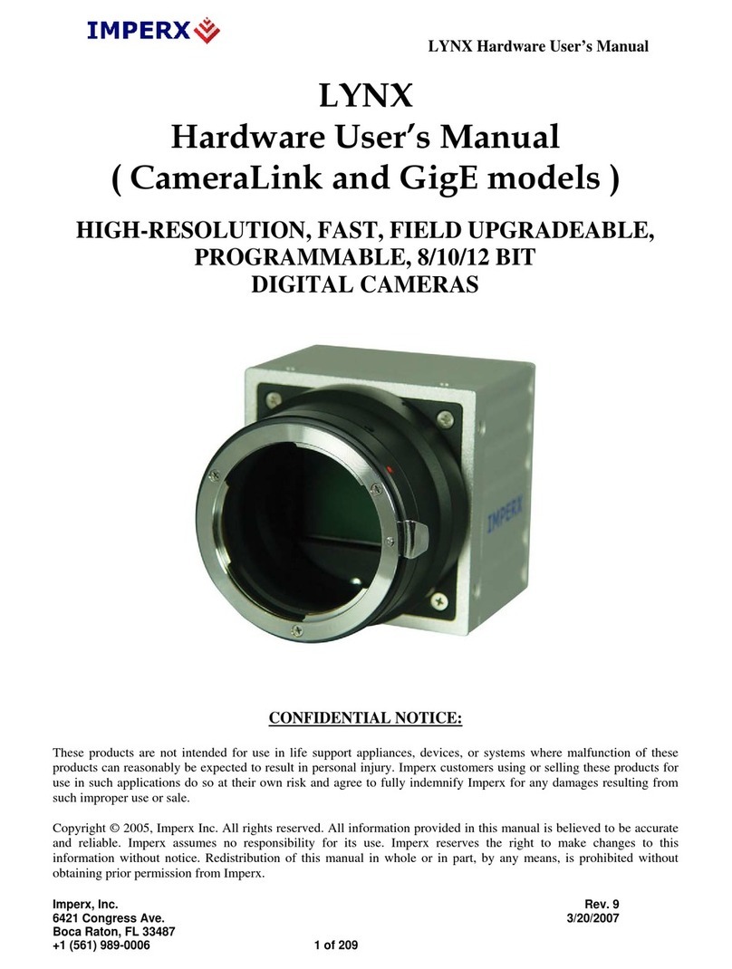
Imperx LYNX IPX-VGA120-L User manual

LYNX Manual RA02
www.imperx.com
IPX-LYNX
HIGH-RESOLUTION, FAST, FIELD UPGRADEABLE,
PROGRAMMABLE, 8/10/12 BIT, CAMERA LINK
DIGITAL CAMERAS
User’s Manual
CONFIDENTIAL NOTICE:
Copyright ©2005, Imperx, Inc. All rights reserved.
Any unauthorized use, duplication or distribution of this document or any part thereof,
without the prior written consent of Imperx Corporation is strictly prohibited.
1of 154 5/6/2005

LYNX Manual RA02
www.imperx.com
Revision History
RA01 04/01/05 P. Dinev First Release
RA02 05/03/05 P. Dinev IPX-VGA90-L deleted, IPX-1M48-L has 1000(H) x 1000(V),
strobe wiring - corrected.
2of 154 5/6/2005

LYNX Manual RA02
www.imperx.com
Table of Contents
Chapter 1 – Introduction______________________________________________________ 12
1.1 LYNX FAMILY ____________________________________________________ 13
1.2 GENERAL DESCRIPTION __________________________________________ 14
1.3 LYNX TECHNICAL SPECIFICATIONS_______________________________ 15
1.4 CAMERA CONNECTIVITY _________________________________________ 21
1.4.1 General Description ______________________________________________ 21
1.4.2 Power Supply ___________________________________________________ 22
1.4.3 Camera Output Connector _________________________________________ 22
1.4.4 Camera Power Connector__________________________________________ 25
1.5 MECHANICAL, OPTICAL and ENVIRONMENTAL____________________ 26
1.5.1 Mechanical _____________________________________________________ 26
1.5.2 Optical_________________________________________________________ 32
1.5.3 Environmental___________________________________________________ 33
Chapter 2 – Camera Features __________________________________________________ 34
2.1 RESOLUTION AND FRAME RATE __________________________________ 35
2.1.1 Single Output ___________________________________________________ 35
2.1.2 Dual Output_____________________________________________________ 36
2.1.3 Center Columns Output (IPX-VGA210-L only) ________________________ 37
2.1.4 Timing Diagrams ________________________________________________ 39
IPX-VGA120-L, IPX-VGA210-L _________________________________________ 39
IPX-VGA210-L – Center Columns Operation _____________________________ 41
IPX-1M48-L__________________________________________________________ 42
IPX-2M30-L__________________________________________________________ 44
IPX-2M30H-L ________________________________________________________ 46
IPX-4M15-L__________________________________________________________ 48
IPX-11M5-L__________________________________________________________ 50
2.2 AREA OF INTEREST _______________________________________________ 52
2.2.1 Horizontal and Vertical Window ____________________________________ 52
2.2.2 Calculating the Frame Rate Using Vertical Window _____________________ 53
IPX-VGA120-L _______________________________________________________ 54
IPX-VGA210-L _______________________________________________________ 55
IPX-1M48-L__________________________________________________________ 56
IPX-2M30-L__________________________________________________________ 57
IPX-4M15-L__________________________________________________________ 58
IPX-11M5-L__________________________________________________________ 59
2.3 BINNING__________________________________________________________ 60
2.4 EXPOSURE CONTROL _____________________________________________ 62
2.4.1 Electronic Shutter ________________________________________________ 62
3of 154 5/6/2005

LYNX Manual RA02
www.imperx.com
2.4.2 Variable Frame Rate – Programmable Integration_______________________ 62
2.4.3 Long Integration _________________________________________________ 63
2.5 EXTERNAL TRIGGER _____________________________________________ 65
2.5.1 Standard Triggering - Programmable Exposure_________________________ 66
2.5.2 Fast Synchronized Triggering – Rapid Capture _________________________ 67
2.5.3 Double Exposure Triggering________________________________________ 68
2.6 STROBE OUTPUT__________________________________________________ 70
2.6.1 Strobe Positioning________________________________________________ 70
2.6.2 Strobe Electrical Connectivity ______________________________________ 70
2.7 GAIN and OFFSET _________________________________________________ 72
2.8 DATA OUTPUT FORMAT___________________________________________ 73
2.9 TRANSFER FUNCTION CORRECTION – USER LUT __________________ 74
2.9.1 Standard Gamma Correction________________________________________ 74
2.9.2 User Defined LUT - Examples______________________________________ 75
2.10 DYNAMIC SIGNAL-TO-NOISE CORRECTION________________________ 80
2.11 IMAGE REVERSAL ________________________________________________ 81
2.12 NEGATIVE IMAGE ________________________________________________ 82
2.13 CAMERA INTERFACE _____________________________________________ 83
2.13.1 Status LED _____________________________________________________ 83
2.13.2 Temperature Monitor _____________________________________________ 83
2.13.3 Integration Time Monitor __________________________________________ 84
2.13.4 Frame Rate Monitor ______________________________________________ 84
2.14 TEST MODE_______________________________________________________ 85
2.15 AUTOMATIC IRIS CONTROL_______________________________________ 86
Chapter 3 – Camera Configuration _____________________________________________ 87
3.1 Overview __________________________________________________________ 88
3.2 Configuration Memory_______________________________________________ 89
3.3 Command Format___________________________________________________ 90
3.4 Command Help_____________________________________________________ 91
3.5 Startup procedure___________________________________________________ 92
3.6 Saving and Restoring Settings_________________________________________ 93
3.6.1 Set Boot From (‘sbf’)______________________________________________ 93
3.6.2 Get Boot From (‘gbf’) _____________________________________________ 93
3.6.3 Load From Factory (‘lff’)___________________________________________ 93
3.6.4 Load From User (‘lfu’)_____________________________________________ 94
3.6.5 Save To Factory (‘stf’)_____________________________________________ 94
3.6.6 Save To User (‘stu’)_______________________________________________ 94
3.7 Retrieving Manufacturing Data _______________________________________ 95
4of 154 5/6/2005

LYNX Manual RA02
www.imperx.com
3.7.1 Get Manufacturing Data (‘gmd’) _____________________________________ 95
3.7.2 Get Assembly Number (‘gan’)_______________________________________ 95
3.7.3 Get Model Number (‘gmn’) _________________________________________ 95
3.7.4 Get Firmware Version (‘gfv’)________________________________________ 95
3.7.5 Get Software Version (‘gsv’) ________________________________________ 96
3.8 Command Description _______________________________________________ 97
3.8.1 Horizontal Window_______________________________________________ 97
3.8.1.1 Set Horizontal Window (‘shw’)_________________________________ 97
3.8.1.2 Get Horizontal Window (‘ghw’)________________________________ 97
3.8.2 Vertical Window_________________________________________________ 98
3.8.2.1 Set Vertical Window (‘svw’)___________________________________ 98
3.8.2.2 Get Vertical Window (‘gvw’)___________________________________ 98
3.8.3 Shutter Time ____________________________________________________ 99
3.8.3.1 Set Shutter Time (‘sst’)_______________________________________ 99
3.8.3.2 Get Shutter Time (‘gst’)______________________________________ 99
3.8.4 Long Integration ________________________________________________ 100
3.8.4.1 Set Long Integration (‘sli’)___________________________________ 100
3.8.4.2 Get Long Integration (‘gli’)___________________________________ 100
3.8.5 Strobe Position _________________________________________________ 101
3.8.5.1 Set Strobe Position (‘ssp’)___________________________________ 101
3.8.5.2 Get Strobe Position (‘gsp’)___________________________________ 101
3.8.6 Analog Gain ___________________________________________________ 102
3.8.6.1 Set Analog Gain (‘sag’)______________________________________ 102
3.8.6.2 Get Analog Gain (‘gag’)_____________________________________ 102
3.8.7 Analog Offset __________________________________________________ 103
3.8.7.1 Set Analog Offset (‘sao’)_____________________________________ 103
3.8.7.2 Get Analog Offset (‘gao’)____________________________________ 103
3.8.8 Dual Tap mode _________________________________________________ 104
3.8.8.1 Set Dual Mode (‘sdm’)_______________________________________ 104
3.8.8.2 Get Dual Mode (‘gdm’)______________________________________ 104
3.8.9 Bit Depth______________________________________________________ 105
3.8.9.1 Set Bit Depth (‘sbd’)________________________________________ 105
3.8.9.2 Get Bit Depth (‘gbd’)________________________________________ 105
3.8.10 Lookup Table Operation__________________________________________ 106
3.8.10.1 Set Lookup Table (‘slt’)______________________________________ 106
3.8.10.2 Get Lookup Table (‘glt’)_____________________________________ 106
3.8.10.3 Get Lookup Header (‘glh’)___________________________________ 106
3.8.11 Noise Correction processing_______________________________________ 107
3.8.11.1 Set Noise Correction (‘snc’)__________________________________ 107
3.8.11.2 Get Noise Correction (‘gnc’)__________________________________ 107
3.8.12 Horizontal mode ________________________________________________ 108
3.8.12.1 Set Horizontal Mode (‘shm’)__________________________________ 108
3.8.12.2 Get Horizontal Mode (‘ghm’)_________________________________ 108
3.8.13 Vertical Mode __________________________________________________ 109
3.8.13.1 Set Vertical Mode (‘svm’)____________________________________ 109
3.8.13.2 Get Vertical Mode (‘gvm’)____________________________________ 109
5of 154 5/6/2005

LYNX Manual RA02
www.imperx.com
3.8.14 Test Pattern generation ___________________________________________ 110
3.8.14.1 Set Test Mode (‘gtm’)_______________________________________ 110
3.8.14.2 Get Test Mode (‘gtm’)_______________________________________ 110
3.8.15 Image Reversal mode ____________________________________________ 111
3.8.15.1 Set Image Reversal (‘sir’)____________________________________ 111
3.8.15.2 Get Image Reversal (‘gir’) ___________________________________ 111
3.8.16 Trigger operation _______________________________________________ 112
3.8.16.1 Set Trigger (‘str’)___________________________________________ 112
3.8.16.2 Get Trigger (‘gtr’)___________________________________________ 112
3.8.16.3 Set Trigger Duration (‘std’)___________________________________ 113
3.8.16.4 Get Trigger Duration (‘gtd’)__________________________________ 113
3.8.16.5 Set CC Integration (‘sci’)____________________________________ 113
3.8.16.6 Get CC Integration (‘gci’)____________________________________ 113
3.8.16.7 Set Pre-Exposure (‘spe’)____________________________________ 114
3.8.16.8 Get Pre-Exposure (‘gpe’)____________________________________ 114
3.8.16.9 Set Double Exposure (‘sde’)_________________________________ 115
3.8.16.10 Get Double Exposure (‘gde’)_________________________________ 115
3.8.17 Negative Image mode____________________________________________ 116
3.8.17.1 Set Negative Image (‘sni’)___________________________________ 116
3.8.17.2 Get Negative Image (‘gni’)___________________________________ 116
3.8.18 Temperature Monitoring__________________________________________ 117
3.8.18.1 Get Current Temperature (‘gct’) ______________________________ 117
3.8.18.2 Set Temperature Alarm (‘sta’)________________________________ 117
3.8.18.3 Get Temperature Alarm (‘gta’)________________________________ 117
3.8.18.4 Set Temperature Threshold (‘stt’)_____________________________ 118
3.8.18.5 Get Temperature Threshold (‘gtt’)____________________________ 118
3.8.19 Programmable Frame Rate ________________________________________ 119
3.8.19.1 Set Frame Rate (‘sfr’)_______________________________________ 119
3.8.19.2 Get Frame Rate (‘gfr’)_______________________________________ 119
3.8.20 Current Speed and Exposure_______________________________________ 120
3.8.20.1 Get Camera Speed (‘gcs’)___________________________________ 120
3.8.20.2 Get Camera Exposure (‘gce’)________________________________ 121
Chapter 4 – Warranty and Support_____________________________________________ 122
4.1 ORDERING INFORMATION _______________________________________ 123
4.2 TECHNICAL SUPPORT____________________________________________ 124
4.3 WARRANTY______________________________________________________ 125
Appendix A – Camera Configuration Reference __________________________________ 126
A.1 General Commands___________________________________________________ 127
A.2 Retrieving Manufacturing Data _________________________________________ 128
A.3 Retrieving Camera Performance ________________________________________ 128
A.4 Restricted Commands _________________________________________________ 129
A.5 Configuring Workspace Settings ________________________________________ 130
6of 154 5/6/2005

LYNX Manual RA02
www.imperx.com
A.6 Retrieving workspace settings___________________________________________ 133
Appendix B – Lynx Configurator ______________________________________________ 136
B.1 Overview ____________________________________________________________ 137
B.2 Discovery Procedure __________________________________________________ 137
B.3 Usage _______________________________________________________________ 138
Appendix C – Lynx Terminal _________________________________________________ 140
C.1 Overview____________________________________________________________ 141
C.2 Setup _______________________________________________________________ 141
C.3 Download Utility _____________________________________________________ 146
C.4 Terminal Utility ______________________________________________________ 147
Appendix D – Creating Look Up Tables_________________________________________ 148
D.1 Overview____________________________________________________________ 149
D.2 Using an ASCII text editor _____________________________________________ 149
D.3 Using Microsoft Excel _________________________________________________ 150
Appendix E – Software Installation ____________________________________________ 151
E.1 Software Suite________________________________________________________ 152
E.2 Software Installation from CD __________________________________________ 153
E.3 Software Upgrade from Web Site________________________________________ 153
7of 154 5/6/2005

LYNX Manual RA02
www.imperx.com
List of Figures
Figure 1.0 - CCD Pixel Structure................................................................................................ 15
Figure 1.1 - Spectral response – monochrome quantum efficiency.......................................... 16
Figure 1.2 - Spectral response – color quantum efficiency........................................................ 17
Figure 1.3 - Spectral response – UV quantum efficiency .......................................................... 17
Figure 1.4 - Camera Back Panel................................................................................................. 21
Figure 1.5 - Camera Output Connector...................................................................................... 22
Figure 1.6 - Camera Power Connector (viewed from rear) ....................................................... 25
Figure 1.7 - C-mount cameras – IPX-VGA/1M48/2M30/2M30H............................................. 26
Figure 1.8 - F-mount cameras – IPX-4M15 and IPX-11M....................................................... 26
Figure 1.9 - IPX-VGA120-L and IPX-VGA0210-L.................................................................... 27
Figure 1.10 - IPX-1M48-L........................................................................................................... 28
Figure 1.11 - IPX-2M30-L and IPX-2M30H-L.......................................................................... 29
Figure 1.12 - IPX-4M15-L........................................................................................................... 30
Figure 1.13 - IPX-11M5-L........................................................................................................... 31
Figure 1.14 - C-mount and F-mount adapter............................................................................. 32
Figure 2.1 - Single Output Mode of Operation........................................................................... 35
Figure 2.2 - Dual Output Mode of Operation............................................................................. 36
Figure 2.3 - Center columns output mode of operation............................................................. 37
Figure 2.4 - Center Columns Output in Dual Mode of Operation ............................................ 38
Figure 2.5 - Center Columns Output in Dual Tap Mode........................................................... 38
Figure 2.6 - Single Output Line Timing (IPX-VGA120/210-L)................................................. 39
Figure 2.7 - Dual Output Line Timing (IPX-VGA120/210-L)................................................... 40
Figure 2.8 - Single / Dual Center Output Frame Timing (IPX-VGA210-L)............................. 40
Figure 2.9 - Center Columns Single Output Line Timing (IPX-VGA210-L)............................ 41
Figure 2.10 - Center Columns Dual Output Line Timing (IPX-VGA210-L)............................ 41
Figure 2.11 - Single Output Line Timing (IPX-1M48-L) .......................................................... 42
Figure 2.12 - Dual Output Line Timing (IPX-1M48-L)............................................................. 42
Figure 2.13 - Single / Dual Output Frame Timing (IPX-1M48-L) ........................................... 43
Figure 2.14 - Single output line timing (IPX-2M30-L).............................................................. 44
Figure 2.15 - Dual output line timing (IPX-2M30-L)................................................................ 44
Figure 2.16 - Single / Dual Output Frame Timing (IPX-2M30-L) ........................................... 45
8of 154 5/6/2005

LYNX Manual RA02
www.imperx.com
Figure 2.17 - Single Output Line Timing (IPX-2M30H-L)....................................................... 46
Figure 2.18 - Dual Output Line Timing (IPX-2M30H-L) ........................................................ 46
Figure 2.19 - Single / Dual Output Frame Timing (IPX-2M30H-L)........................................ 47
Figure 2.20 - Single Output Line Timing (IPX-4M15-L) .......................................................... 48
Figure 2.21 - Dual Output Line Timing (IPX-4M15-L)............................................................. 48
Figure 2.22 - Single / Dual Output Frame Timing (IPX-4M15-L) ........................................... 49
Figure 2.23 - Single Output Line Timing (IPX-11M5-L) .......................................................... 50
Figure 2.24 - Dual Output Line Timing (IPX-11M5-L)............................................................. 50
Figure 2.25 - Single / Dual Output Frame Timing (IPX-11M5-L) ........................................... 51
Figure 2.26 - Horizontal and Vertical Window Positioning...................................................... 52
Figure 2.27 - Frame Rate vs. Vertical Window Size (IPX-VGA120-L)..................................... 54
Figure 2.28 - Frame Rate vs. Vertical Window Size (IPX-VGA210-L)..................................... 55
Figure 2.29 - Frame Rate vs. Vertical Window Size (IPX-1M48-L).......................................... 56
Figure 2.30 - Frame Rate vs. Vertical Window Size (IPX-2M30-L).......................................... 57
Figure 2.31 - Frame Rate vs. Vertical Window Size (IPX-4M15-L).......................................... 58
Figure 2.32 - Frame Rate vs. Vertical Window Size (IPX-11M5-L).......................................... 59
Figure 2.33 - Horizontal and Vertical Binning.......................................................................... 60
Figure 2.34 - Electronic Shutter Position................................................................................... 62
Figure 2.35 – Programmable Frame Rate.................................................................................. 63
Figure 2.36 - Long Integration.................................................................................................... 64
Figure 2.37 - Hardware Trigger Electrical Connection............................................................. 66
Figure 2.38 - Standard Triggering Timing................................................................................. 67
Figure 2.39 - Fast Synchronized Triggering - Rapid Capture................................................... 68
Figure 2.40 - Double Exposure Triggering................................................................................ 69
Figure 2.41 - Strobe Pulse Positioning....................................................................................... 70
Figure 2.42 - Strobe Output Electrical Connection (Internal) .................................................. 71
Figure 2.43 – Recommended External Strobe Output Electrical Connection.......................... 71
Figure 2.44 - AFE Gain and Offset ............................................................................................ 72
Figure 2.45 - Data Output Format.............................................................................................. 73
Figure 2.46 - Look Up Table....................................................................................................... 74
Figure 2.47 - Gamma Corrected Video Signal........................................................................... 75
Figure 2.48 - Custom LUT .......................................................................................................... 76
Figure 2.49 - Knee Correction..................................................................................................... 76
9of 154 5/6/2005

LYNX Manual RA02
www.imperx.com
Figure 2.50 - Contrast Correction............................................................................................... 77
Figure 2.51 - Negative Image...................................................................................................... 77
Figure 2.52 - Dynamic Signal-to-Noise Correction ................................................................... 80
Figure 2.53 - Normal and Mirror Image.................................................................................... 81
Figure 2.54 - Normal and Negative Image................................................................................. 82
Figure 2.55 - Fixed Pattern #1: Single and Dual Modes.......................................................... 85
Figure 2.56 - Fixed Pattern #2: Single and Dual Modes.......................................................... 85
Figure B.1 – Select Port dialog ................................................................................................. 137
Figure B.2 – LynxConfigurator graphical user interface........................................................ 138
Figure B.3 – Terminal dialog.................................................................................................... 139
Figure C.1 – LynxTerminal main dialog.................................................................................. 141
Figure C.2 – Plug-in Properties dialog..................................................................................... 142
Figure C.3 – Serial Transport Properties dialog...................................................................... 143
Figure C.4 – Camera Link Transport Properties dialog.......................................................... 144
Figure C.5 – Transport dialog................................................................................................... 145
Figure C.6 – Loader View dialog.............................................................................................. 146
Figure C.7 –Terminal View dialog............................................................................................ 147
10 of 154 5/6/2005

LYNX Manual RA02
www.imperx.com
List of Tables
Table 1.0 - Pixel structure for different LYNX cameras............................................................ 16
Table 1.1 - Camera Specifications............................................................................................... 18
Table 1.2 - Camera Output Connector – Signal Mapping ......................................................... 23
Table 1.3 - Base Camera Link bit assignment............................................................................ 24
Table 1.4 - Camera Power Connector Pin Mapping.................................................................. 25
Table 1.5 - BNC Connectors Pin Mapping................................................................................. 25
Table 2.1 - Pixel Structure and Frame Rates ............................................................................. 35
Table 2.2 - Allowable Horizontal and Window Sizes.................................................................. 53
Table A.1 – General commands ................................................................................................ 127
Table A.2 – Retrieving manufacturing data ............................................................................. 128
Table A.3 – Retrieving camera performance............................................................................ 128
Table A.4 – Restricted commands............................................................................................. 129
Table A.5 – Workspace ‘SET’ commands................................................................................. 132
Table A.6 – Workspace ‘GET’ commands................................................................................ 135
11 of 154 5/6/2005

LYNX Manual RA02
www.imperx.com
Chapter 1 – Introduction
Introduction
This chapter outlines the key features of the Lynx camera.
12 of 154 5/6/2005

LYNX Manual RA02
www.imperx.com
1.1 LYNX FAMILY
The LYNX series of cameras are built around a robust imaging platform utilizing
the latest digital technology. The camera’s image processing engine is based on a
1 million gate FPGA and a 32-bit RISC processor.
The LYNX family consists of the following 14 cameras:
High Speed:
IPX-VGA120-L 640x480 120fps monochrome
IPX-VGA120-LC 640x480 120fps color
IPX-VGA210-L 640x480 210fps monochrome
IPX-VGA210-LC 640x480 210fps color
Mega-pixel:
IPX-1M48-L 1000x1000 48fps monochrome
IPX-1M48-LC 1000x1000 48fps color
IPX-2M30-L 1600x1200 30fps monochrome
IPX-2M30-LC 1600x1200 30fps color
IPX-2M30H-L 1920x1080 30fps monochrome
IPX-2M30H-LC 1920x1080 30fps color
IPX-4M15-L 2048x2048 15fps monochrome
IPX-4M15-LC 2048x2048 15fps color
IPX-11M5-L 4000x2672 5fps monochrome
IPX-11M5-LC 4000x2672 5fps color
13 of 154 5/6/2005

LYNX Manual RA02
www.imperx.com
1.2 GENERAL DESCRIPTION
The LYNX cameras are advanced, high-resolution, progressive scan, fully
programmable and field upgradeable CCD cameras. They are built around
KODAK’s line of interline transfer CCD imagers. The camera’s image processing
engine is based on a 1 million gate FPGA and 32-bit RISC processor. The LYNX
cameras feature programmable image resolution, frame rates, gain, offset,
asynchronous external triggering with programmable exposure, fast triggering,
double exposure and capture duration, electronic shutter, long time integration,
strobe output, transfer function correction, temperature monitoring and user
programmable and up-loadable LUT. A square imager format with uniform 7.4
µm square pixels provides for a superior image in any orientation. The interline
transfer CCD permits full vertical and horizontal resolution of high-speed shutter
images. The combination of electronic shutter and long time integration enables
the cameras capturing speed to be from 1/200,000 second to more than 10
seconds. The cameras have an optically isolated I/O interface (trigger input and
strobe output). A built-in Gamma correction and user LUT optimizes the CCD ‘s
dynamic range. The cameras have a standard Camera Link™ interface that
includes 8/10/12 bits data transmission with one or two output taps as well as
camera control and asynchronous RS232 serial communication interface, all on a
single cable. The cameras are fully programmable via the Camera Link serial
interface using a GUI based configuration utility, or optionally, the camera can be
configured using simple ASCII commands via any terminal emulator. The
adaptability and flexibility of the camera allows it to be used in a wide and
diverse range of applications including machine vision, metrology high-definition
imaging and surveillance, medical and scientific imaging, intelligent
transportation systems, character recognition, document processing and many
more.
MAIN LYNX FEATURES
• Interline transfer CCD
• Progressive scan image
• 8/10/12 bit data, Base Camera Link
• Single or Dual tap operation
• RS232 serial communication
• 32 bit RISC processor
• Horizontal and vertical binning
• Dynamic transfer function correction
• Dynamic S/N correction
• Temperature monitor
• Field upgradeable
• Software
• Firmware
• User LUTs
• Automatic Iris Control – optional
• Highly programmable:
• Resolution
• Frame rate
• Electronic shutter
• Long integration
• Strobe output
• Analog gain
• Analog offset
• Area of interest
• User LUT
• Temperature alarms
• External trigger
• Pre-exposure
• Fast triggering
• Double exposure
• Capture duration
14 of 154 5/6/2005

LYNX Manual RA02
1.3 LYNX TECHNICAL SPECIFICATIONS
A CCD camera is an electronic device for converting light into an electrical
signal. The camera contains a light sensitive element CCD (Charge Coupled
Device) where an electronic representation of the image is formed. The CCD
consists of a two dimensional array of sensitive elements – silicon photodiodes,
also known as pixels. The photons falling on the CCD surface create
photoelectrons within the pixels, where the number of photoelectrons is linearly
proportional to the light level. Although the number of electrons collected in each
pixel is linearly proportional to the light level and exposure time, the amount of
electrons varies with the wavelength of the incident light. When the desired
exposure is reached, the charges from each pixel are shifted onto a vertical
register, VCCD, and then one row downwards in a vertical direction towards a
horizontal register, HCCD. After that the electrons contained in the HCCD are
shifted in a horizontal direction, one pixel at a time, onto a floating diffusion
output node where the transformation from charge to voltage takes place. The
resultant voltage signal is buffered by a video amplifier and sent to the
corresponding video output. There are two floating diffusions and two video
amplifiers at each end of the HCCD, and the charges can be transferred towards
any of the outputs (depending on the mode of operation). The time interval
required for all the pixels, from the entire imager, to be clocked out of the HCCD
is called a frame. To generate a color image a set of color filters (Red, Green,
Blue) arranged in a “Bayer” pattern, are placed over the pixels. The starting color
is Green. Figure 1.1 shows the CCD pixel structure. Table 1.1 shows the
individual pixel structure for different LYNX cameras. Figures 1.2, 1.3 and 1.4
show the camera’s spectral response.
Figure 1.0 - CCD Pixel Structure
www.imperx.com 15 of 154 5/6/2005

LYNX Manual RA02
Features
IPX-
VGA120/
210-L IPX-
1M48-L IPX-
2M30-L IPX-
2M30H-L IPX-
4M15-L IPX-
11M5-L
CCD sensor KAI-0340S/D KAI-1020 KAI-2020 KAI-2093 KAI-4021 KAI-11000
Pixel size 7.4 µm 7.4 µm 7.4 µm 7.4 µm 7.4 µm 9.0 µm
Black rows - top 4 4 2 4 10 16
Buffer rows - top 4 2 4 2 6 8
Active rows - (V) 480 1000 1200 1080 2048 2672
Buffer rows - bottom 4 2 4 2 8 8
Black rows - bottom 0 0 4 4 0 16
Dummy pixels - left 12 8 4 4 12 4
Black columns - left 24 12 16 28 28 20
Buffer columns - left 4 2 4 4 4 16
Active pixels - (H) 640 1000 1600 1920 2048 4000
Buffer columns - right 4 2 4 4 4 16
Black columns - right 24 12 16 28 28 20
Dummy pixels - right 12 8 4 4 12 4
Frame rate - single 120 fps 30 fps 17 fps 16 fps 7.5 fps 2.5 fps
Frame rate - dual 120/210 fps 48 fps 33 fps 33 fps 15 fps 5 fps
Table 1.0 - Pixel structure for different LYNX cameras.
Figure 1.1 - Spectral response – monochrome quantum efficiency
(Measured with the cover glass)
www.imperx.com 16 of 154 5/6/2005

LYNX Manual RA02
Figure 1.2 - Spectral response – color quantum efficiency
(Measured with the cover glass)
Figure 1.3 - Spectral response – UV quantum efficiency
(Measured without the cover glass)
www.imperx.com 17 of 154 5/6/2005

LYNX Manual RA02
Specifications IPX-VGA120-L IPX-VGA210-L
A
ctive image pixels 640 (H) x 480 (V) 640 (H) x 480 (V)
A
ctive image area 5.87 mm x 4.71 mm
(0.231” x 0.185”) 5.87 mm x 4.71 mm
(0.231” x 0.185”)
Pixel size 7.4 µm 7.4 µm
V
ideo output Digital, 8/10/12 bit,
one output Digital, 8/10/12 bit,
one or two outputs
Tap reordering Yes Yes
Data clock 40.000 MHz 40.000 MHz
Camera interface Base Camera Link Base Camera Link
RS 232 interface Yes Yes
Resolution 640 x 480 pixels 640 x 480 pixels
Nominal frame rate 120 fps 210 fps
Maximum frame rate up to 1000 fps up to 3000 fps
S/N ratio 60 dB 60 dB
Binning 1 x 1, 2 x 2 1 x 1, 2 x 2
A
rea of interest 2 x 2 pixels min. size 2 x 2 pixels min. size
Mirror image Yes Yes
Negative image Yes Yes
Test image Yes Yes
Shutter speed 1/100000 to 1/100 sec 1/200000 to 1/100 sec
Long integration Up to 10 sec Up to 10 sec
Gamma correction G=1.0, G=0.45, user LUT G=1.0, G=0.45, user LUT
Black level offset 256 levels per output 256 levels per output
V
ideo gain 6 to 40 dB per output 6 to 40 dB per output
Gain resolution 0.0351 dB/step, 1024 steps 0.0351 dB/step, 1024 steps
Hardware trigger Asynchronous, active HIGH,
optically isolated Asynchronous, active HIGH,
optically isolated
Software trigger Asynchronous, frame-grabber
via CC1 Asynchronous, frame-
grabber via CC1
Trigger modes Normal, double exposure, fast
triggering Normal, double exposure,
fast triggering
Strobe output Active HIGH Active HIGH
Camera housing Solid, anodized aluminum Solid, anodized aluminum
Size (W x H x L) mm 67 x 67 x 41 67 x 67 x 41
Weight 280 g 280 g
Min. illumination 1.0 Lux, f=1.4 1.0 Lux, f=1.4
Lens Mount C mount, 1/3” format C mount, 1/3” format
Power input range 10 V to 15 V DC 10 V to 15 V DC
Power consumption 4.0 W 4.2 W
Upgradeable firmware Yes Yes
Upgradeable software Yes Yes
Environmental Operating: -5 to 50 C
Storage: -10 to 65 C Operating: -5 to 50 C
Storage: -10 to 65 C
Relative humidity 80% non-condensing 80% non-condensing
Table 1.1 - Camera Specifications
www.imperx.com 18 of 154 5/6/2005

LYNX Manual RA02
Specifications IPX-1M48-L IPX-2M30-L IPX-2M30H-L
A
ctive image pixels 1000 (H) x 1000 (V) 1600 (H) x 1200 (V) 1920 (H) x 1080 (V)
A
ctive image area 8.90 mm x 8.20 mm
(0.350” x 0.320”) 13.38 mm x 9.52 mm
(0.527” x 0.375”) 15.90 mm x 8.61 mm
(0.626” x 0.339”)
Pixel size 7.4 µm 7.4 µm 7.4 µm
V
ideo output Digital, 8/10/12 bit,
one or two outputs Digital, 8/10/12 bit,
one or two outputs
Tap reordering Yes Yes Yes
Data clock 40.000 MHz 40.000 MHz 40.000 MHz
Camera interface Base Camera Link Base Camera Link Base Camera Link
RS 232 interface Yes Yes Yes
Resolution 1000 x 1000 pixels 1600 x 1200 pixels 1920 x 1080 pixels
Nominal frame rate 48 fps 33 fps 33 fps
Maximum frame rate up to 140 fps up to 200 fps up to 60 fps
S/N ratio 60 dB 60 dB 60 dB
Binning 1 x 1, 2 x 2 1 x 1, 2 x 2 1 x 1, 2 x 2
A
rea of interest 2 x 2 pixels min. size 2 x 2 pixels min. size 2 x 2 pixels min. size
Mirror image Yes Yes Yes
Negative image Yes Yes Yes
Test image Yes Yes Yes
Shutter speed 1/50000 to 1/30 sec 1/40000 to 1/15 sec 1/35000 to 1/15 sec
Long integration Up to 10 sec Up to 10 sec Up to 10 sec
Gamma correction G=1.0, G=0.45, user LUT G=1.0, G=0.45, user LUT G=1.0, G=0.45, user LUT
Black level offset 256 levels per output 256 levels per output 256 levels per output
V
ideo gain 0 to 36 dB per output 6 to 40 dB per output 6 to 40 dB per output
Gain resolution 0.0351 dB/step, 1024 steps 0.0351 dB/step, 1024 steps 0.0351 dB/step, 1024 steps
Hardware trigger Asynchronous, active HIGH,
optically isolated Asynchronous, active HIGH,
optically isolated
Software trigger Asynchronous, frame-grabber
via CC1 Asynchronous, frame-grabber
via CC1
Trigger modes Normal, double exposure,
fast triggering Normal, double exposure, fast
triggering Normal, double exposure,
fast triggering
Strobe output Active HIGH Active HIGH Active HIGH
Camera housing Solid, anodized aluminum Solid, anodized aluminum Solid, anodized aluminum
Size (W x H x L) 67 x 67 x 41 67 x 67 x 47 67 x 67 x 47
Weight 280 g 310 g 310 g
Min. illumination 1.0 Lux, f=1.4 1.0 Lux, f=1.4 1.0 Lux, f=1.4
Lens Mount C mount, 2/3” format C mount, 1” format C mount, 1” format
Power input range 10 V to 15 V DC 10 V to 15 V DC 10 V to 15 V DC
Power consumption 3.6 W 4.8 W 4.8 W
Upgradeable firmware Yes Yes Yes
Upgradeable software Yes Yes Yes
Environmental Operating: -5 to 50 C
Storage: -10 to 65 C Operating: -5 to 50 C
Storage: -10 to 65 C
Relative humidity 80% non-condensing 80% non-condensing 80% non-condensing
Table 1.1 - Camera Specifications (cont.)
www.imperx.com 19 of 154 5/6/2005

LYNX Manual RA02
Specifications IPX-4M15-L IPX-11M5-L
A
ctive image pixels 2048 (H) x 2048 (V) 4000 (H) x 2672 (V)
A
ctive image area 16.67 mm x 16.05 mm
(0.656” x 0.632”) 37.25 mm x 25.70 mm
(1.466” x 1.012”)
Pixel size 7.4 µm 9.0 µm
V
ideo output Digital, 8/10/12 bit,
one or two outputs Digital, 8/10/12 bit,
one or two outputs
Tap reordering Yes Yes
Data clock 40.000 MHz 28.000 MHz
Camera interface Base Camera Link Base Camera Link
RS 232 interface Yes Yes
Resolution 2048 x 2048 pixels 4000 x 2672 pixels
Nominal frame rate 15 fps 5 fps
Maximum frame rate up to 115 fps up to 49 fps
S/N ratio 60 dB 60 dB
Binning 1 x 1, 2 x 2 1 x 1, 2 x 2
A
rea of interest 2 x 2 pixels min. size 2 x 2 pixels min. size
Mirror image Yes Yes
Negative image Yes Yes
Test image Yes Yes
Shutter speed 1/30000 sec to 1/7 sec 1/12000 sec to 1/3 sec
Long integration Up to 10 sec Up to 10 sec
Gamma correction G=1.0, G=0.45, user LUT G=1.0, G=0.45, user LUT
Black level offset 256 levels per output 256 levels per output
V
ideo gain 6 to 40 dB per output 6 to 40 dB per output
Gain resolution 0.0351 dB/step, 1024 steps 0.0351 dB/step, 1024 steps
Hardware trigger Asynchronous, active HIGH,
optically isolated Asynchronous, active HIGH,
optically isolated
Software trigger Asynchronous, frame-grabber
via CC1 Asynchronous, frame-grabber
via CC1
Trigger modes Normal, double exposure, fast
triggering Normal, double exposure, fast
triggering
Strobe output Active HIGH Active HIGH
Camera housing Solid, anodized aluminum Solid, anodized aluminum
Size (W x H x L) 67 x 67 x 47 67 x 67 x 47
Weight 360 g 390 g
Min. illumination 1.0 Lux, f=1.4 1.0 Lux, f=1.4
Lens Mount F mount, 22mm format F mount, 43mm format
Power input range 10 V to 15 V DC 10 V to 15 V DC
Power consumption 5.2 W 6.0 W
Upgradeable firmware Yes Yes
Upgradeable software Yes Yes
Environmental Operating: -5 to 50 C
Storage: -10 to 65 C Operating: -5 to 50 C
Storage: -10 to 65 C
Relative humidity 80% non-condensing 80% non-condensing
Table 1.1 - Camera Specifications (cont.)
www.imperx.com 20 of 154 5/6/2005
This manual suits for next models
13
Table of contents
Other Imperx Digital Camera manuals

Imperx
Imperx bobcat User manual

Imperx
Imperx Cheetah Pregius Series User manual

Imperx
Imperx Cheetah C2020 User manual

Imperx
Imperx Cheetah CXP-C9440 User manual

Imperx
Imperx bobcat hd-sdi User manual

Imperx
Imperx Camera Link PoCL User manual

Imperx
Imperx Cheetah C5180 Instructions for use

Imperx
Imperx Cheetah Python Series User manual

Imperx
Imperx Cheetah Series User manual

Imperx
Imperx Cheetah Series User manual