impress Handi-Fan User manual

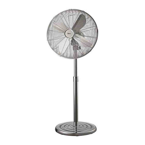
Handi-Fan 16” Stand Fan
Model no. IM-716W & IM-717B
READ AND SAVE THIS USE AND CARE B K
C NSERVER CE GUIDE D’ENTRETIEN ET D’UTILISATI N
P R FAV R LEA ESTE INSTRUCTIV ANTES DE USAR EL
PR DUCT
VENTILATEUR SUR PIED DE 40 CM
VENTILAD R DE PEDESTAL DE 40 CM
IM-717B (Black)
IM-716W (White)

1 - English
SAFETY PRECAUTI NS
PERATING INSTRUCTI NS
READ AND SAVE THESE IMP RTANT
SAFETY INSTRUCTI NS
before using this fan. When using electrical
appliances, basic safety precautions should
always be followed including the following:
1) Use this fan only as described in this man-
ual. ther uses not recommended may
cause fire or electric shock.
2) This product is intended for household
use NLY and not for commercial, industri-
al or outdoor use.
3) To protect against electrical shock, do
not place fan in window, immerse unit, plug,
or cord in water, or spray with liquids.
4) Close supervision is necessary when any
appliance is used near children.
5) Unplug the fan from the outlet when not
in use, when moving fan from one location
to another and before cleaning.
6) Do not operate the fan in the presence of
explosive and/or flammable fumes.
7) Do not place the fan or any parts near an
open flame, cooking or other heating appli-
ance.
8) Do not operate the fan with a damaged
cord, plug, after a malfunction, or if dropped
or damaged in any manner.
9) Avoid contact with moving fan parts.
10) To disconnect, grip the plug and pull it
from the wall outlet. Never yank the cord.
11) The use of attachments is not recom-
mended and may cause hazards.
12) Always use on a dry level surface.
13) Do not operate if the fan housing is
removed or damaged.
14) This appliance has a polarized plug (one
prong is wider than the other) with a
replaceable fuse. To reduce the risk of elec-
tric shock, this plug is intended to fit in a
polarized outlet only one way. If the plug
does not fit fully in the outlet, reverse the
plug. If it still does not fit, contact a qualified
electrician.
WARNING: D N T USE THIS FAN WITH
ANY ADDITI NAL DEVICES T
ALTER/CHANGE THE SPEED F THIS FAN
(EX: S LID STATE SPEED C NTR L
DEVICE). SAVE THESE INSTRUCTI NS
• Store the fan in a cool dry place.
SAVE THESE INSTRUCTI NS.
F R H USEH LD USE NLY
PERATI N
To turn on the fan, press one of the
speed buttons on the control panel
of the fan. To turn FF the fan,
press the 0 button on the control
panel of the fan.
SCILLATI N
To turn on the oscillation feature,
push down the clutch knob on
the top of the motor housing. To
turn off the oscillation feature, pull
the clutch knob up.
OFF
LOW
MEDIUM
HIGH
ON OFF

English - 2
ASSEMBLY
N TE: Remove all contents from box and make sure that
all parts are present.
Step 1: Constructing the base and poles (Fig.1)
1. Connect the cross-bar base (S) together by matching
the slots in both pieces. Secure the base of the outer
pole (Q) to the cross-bar base (S) with the 4 base
screws (T) provided. N TE: The inner pole may be inside
the outer pole. Place finger down the hole and pull out
inner pole.
2. Remove the height adjustment knob ( ) from the
outer (Q) and inner (P) poles by turning it counterclock-
wise. Feed the inner (P) and outer (Q) pole through the
base cap (R), and slide the base cap (R) to the bottom
of the outer pole (Q).
3. Feed the inner pole (P) through the height adjust-
ment knob ( ) and extend the inner pole (P) to the
desired height. Secure the inner pole by turning the
height adjustment knob ( ) clockwise.
(Fig. 1)
1
Secure the
base of the outer pole (P) to the cross-bar
base (R) with the 4 base screws (S) provide
Place finger down the hole and pull out
i
the outer (P) an
couFeed the inner (O) and
outer (P) pole through the base cap (Q), and
slide the base cap (Q) to the bottom of the
outer pole (P).
3
adjustment knob (N) an
pole (O) to the desired height. Secure the
inner pole by turning the height adjustment
kno
control box (Fig. 2)
1
control box, by turning it counter-clockwise,
(DO NOT REMOVE THE LOCK SCREW
COMPLETELY) the
and control box (J and L) on top of the inner
pole (O), the
secure it to the inner pole (O) by turning
it clockwise.
S
screw hole pointing downward) (F)
by aligning the guide holes with
the two rou
12 o'clock an
on the Motor Housing (J). Screw on
the grill lock nut (E) clockwise to
secure the rear grill (F) to
the motor housing (J).
2
the hole on the Fan Blad
matching the pron
Shaft (H) to the pron
the back of the Fan Blade (
Secure the Fan Blad
Blad
it cou
3
rear grill (F) using the grill ho
at the bottom of the front grill.
T
with the grill clips (B) on the
outer ed
AB C D E FGH
IJ
K
L
M
N
O
P
Q
R
S
T
U
A) Plastic Grill Cover with
Screws (3)
B) Front Grill
C) Grill Clip
D) Blade Cap
E) Blade
F) Grill Lock Nut
G) Rear Grill
H) Control Panel
I) Motor Shaft
J) scillation Clutch Knob
K) Motor Head
L) Handle
M) Control Box
N) Lock Screw
) Height Adjustment Knob
P) Inner Pole
Q) uter Pole
R) Base Cap
S) Base Legs
T) Base Screws (4)
U) Safety Plug with Fuse
PARTS
DESCRIPTI N
Fig. 1
F
(
mb
P
t
F o
o
a
p
k
C
s
s
1
o
t
t
S
re
a

3 - English
Step 2: Positioning the motor housing and
control box (Fig.2)
1. Remove the lock screw (N) on the back of
the control box, by turning it counter-clock-
wise, (D N T REM VE THE L CK SCREW
C MPLETELY) then place the motor hous-
ing and control box (K and M) on top of the
inner pole (P), then use the lock screw (N)
to secure it to the inner pole (P) by turning
it clockwise.
Step 3: Assembling the fan head (Fig.3)
1. Attach grill cover (A) onto front grill (B)
using supplied screws.
2. Position the rear grill (small nut and
screw hole pointing downward) (G) by
aligning the guide holes with the two round
pegs located at the 12 o'clock and 6 o'clock
positions on the Motor Housing (K). Screw
on the grill locknut (F) clockwise to secure
the rear grill (G) to the motor housing (K).
3. Insert the Motor Shaft (I) through the
hole on the Fan Blade (E) by matching the
prongs on the Motor Shaft (I) to the prong
notches on the back of the Fan Blade (E).
Secure the Fan Blade (E) with the Blade
Cap (D) by turning it counterclockwise.
4. Place the front grill (B) onto the rear grill
(G) using the grill hook at the bottom of the
front grill. Then secure both grills together
with the grill clips (C) on the outer edge of
the front grill (B).
Fig. 3
Small screw and nut may be attached to the
bottom of the front grill. Remove before attach-
ing front and rear grills together, then re-attach
to the 2 grills for added security.
Small Nut and Screw
(
mb
P
t
Fo
o
a
p
k
C
s
s
1
o
t
t
S
re
a
Fig. 2
(
mb
P
t
F o
o
a
p
k
C
s
s
1
o
t
t
S
re
a
Ta b
FUSE REPLACEMENT
1. Slide the fuse door on the
plug upward using the tab.
2. Using a flat head jewelers
screw driver (smallest one)
gently pry the fuse out from
the bottom.
NOTE: Please becareful when
performing the above
instructions.
3. Replace with a new
2.5Amp/125V fuse, then slide
the door closed.
NOTE: DO NOT USE FUSES
THAT ARE RATED HIGHER
THAN 2.5Amps/125V

English - 4
CLEANING AND
ST RAGE
1. Turn the unit FF and unplug the
unit before cleaning.
2. Use only a soft, damp cloth to clean
the exterior. A can of
compressed air or a vacuum cleaner
can be used to clean the
inside of the motor
3. Do not immerse the unit in water
and never allow water to drip into
the motor housing.
4. Do not use gasoline, paint thinner or
other chemicals to clean the fan.
5. Store the unit in the original box and
store in a cool, dry place.
N TE: If you experience a problem,
please return the unit to
the place of the original purchase or
see your warranty. Do not
attempt to open the motor housing
yourself. Doing so may void
your warranty and cause damage to
the fan or personal injury.
WA ANTY
Length of Warranty
1 year from date of purchase
Within 1 year from date of purchase,
1) eturn product to place of purchase (if
your dealer allows)
O
2) Send product postage pre-paid to:
I.E.A.C.
3030 E. Vernon Ave.
Vernon, CA 90058
Please include original dated receipt, explana-
tion of defect and return name and address as
well as a contact phone number. We will, with-
in 10 days of receiving your product, return a
new or refurbished (at our discretion) product
at NO ADDITIONAL CHA GE. We will also
return your receipt. If product is found to be in
working condition, we will return product
postage collect.
PACK YOU P ODUCT WELL!
We will not be responsible for damages
incurred as a result of improper packing.
Or contact us via e-mail at
customerservice@betterchefimpress.com
TR UBLESH TING
Problem
Unit will not oscillate
The fan is unstable
Clutch knob is not
pushed down.
Push the clutch
knob down.
Unit will not work.
1. Unit is unplugged.
2. utlet is not
receiving power.
3. Fuse in plug
has gone bad.
1. uter pole is not
secured firmly in
the cross-bar base.
2. Fan is not on a
level surface.
1. Make sure outer pole
is screwed tightly into
the cross-bar base.
2. Move fan to a level
surface.
1. Plug unit into
available outlet.
2. Make sure outlet is live.
3. Replace the fuse
(See fuse replacement
instruction).
Possible cause Solution

5 - Français
PRÉCAUTI NS
M DE D'EMPL I
LIRE ET C NSERVER CES C NSIGNES DE
SÉCURITÉ
avant de se servir de ce ventilateur. Lors de l'utili-
sation d'appareils ménagers, des précautions de
base sont toujours à prendre, notamment:
1)Utiliser le ventilateur conformément à ce qui est
décrit dans ce manuel. Un incendie ou des
décharges électriques risquent d'être provoqués
par des utilisations non recommandées.
2)Ce produit est prévu pour un usage ménager
UNIQUEMENT et non pour des utilisations com-
merciales, industrielles ou en extérieur.
3) Pour se protéger des décharges électriques, ne
pas placer le ventilateur dans une fenêtre, ne pas
immerger l'appareil, le cordon ou la fiche dans de
l'eau et ne pas le vaporiser avec du liquide.
4) Une surveillance étroite est nécessaire lorsque
l'appareil se trouve à proximité d'enfants.
5) Débrancher la prise de l'appareil lorsque ce
dernier n'est pas utilisé, lors des déplacements et
avant de le nettoyer.
6) Ne pas faire fonctionner le ventilateur en
présence de vapeurs explosives ou inflammables.
7) Ne pas placer le ventilateur à proximité de
flammes ou d'appareils de cuisine ou chauffants.
8) Ne pas faire fonctionner le ventilateur si le cor-
don ou la prise est endommagé, après un dysfonc-
tionnement ou encore s'il a chuté ou qu'il est
endommagé.
9) Éviter tout contact avec les pièces mobiles.
10) Pour le débrancher, saisir la fiche avec la main
et la retirer de la prise murale. Ne jamais tirer sur
le cordon.
11) L'utilisation d'accessoires n'est pas recom-
mandée et pourrait provoquer des dangers.
12) Toujours utiliser sur une surface sèche et plane
13) Ne pas utiliser sans la grille ou lorsque cette
dernière est endommagée.
14) Cet appareil est muni d'une fiche polarisée
(une des broches est plus longue que l'autre) avec
fusible remplaçable. Pour réduire le risque de
décharge électrique, la fiche ne rentre dans la
prise polarisée que d'une seule façon. Si la fiche
ne rentre pas complètement dans la prise, invers-
er le sens. Si elle ne rentre toujours pas, contacter
un électricien qualifié.
AVERTISSEMENT : NE PAS UTILISER CET
APPAREIL AVEC D'AUTRES D NT LE BUT EST
D'ALTÉRER/M DIFIER LA VITESSE DU VENTILA-
TEUR (PAR EX.: UN DISP SITIF DE RÉGLAGE DE
VITESSE À SEMI-C NDUCTEURS). C NSERVER
CES C NSIGNES
• Ranger le ventilateur dans un endroit sec et frais.
C NSERVER CES C NSIGNES.
RÉSERVÉ À UN USAGE MÉNAGER
F NCTI NNEMENT
Pour allumer le ventilateur, appuyer
sur un des boutons de vitesse du
panneau de commande. Pour étein-
dre le ventilateur, appuyer sur le
bouton 0 du panneau de com-
mande.
SCILLATI N
Pour activer la fonction d'oscillation,
enfoncer le bouton d'enclenche-
ment situé en haut du boîtier
moteur. Pour désactiver la fonction
d'oscillation, remonter le bouton
d'enclenchement
ÉTEINT
FAIBLE
MOYEN
ÉLEVÉ
ALLUMÉ ÉTEINT

Français - 6
(Fig. 1)
1
Secure the
base of the outer pole (P) to the cross-bar
base (R) with the 4 base screws (S) provide
Place finger down the hole and pull out
i
the outer (P) an
couFeed the inner (O) and
outer (P) pole through the base cap (Q), and
slide the base cap (Q) to the bottom of the
outer pole (P).
3
adjustment knob (N) an
pole (O) to the desired height. Secure the
inner pole by turning the height adjustment
kno
control box (Fig. 2)
1
control box, by turning it counter-clockwise,
(DO NOT REMOVE THE LOCK SCREW
COMPLETELY) the
and control box (J and L) on top of the inner
pole (O), the
secure it to the inner pole (O) by turning
it clockwise.
S
screw hole pointing downward) (F)
by aligning the guide holes with
the two rou
12 o'clock an
on the Motor Housing (J). Screw on
the grill lock nut (E) clockwise to
secure the rear grill (F) to
the motor housing (J).
2
the hole on the Fan Blad
matching the pron
Shaft (H) to the pron
the back of the Fan Blade (
Secure the Fan Blad
Blad
it cou
3
rear grill (F) using the grill ho
at the bottom of the front grill.
T
with the grill clips (B) on the
outer ed
AB C D E FGH
IJ
K
L
M
N
O
P
Q
R
S
T
U
A) Cache en plastique avec
vis (3)
B) Grille avant
C) Clip
D) Capuchon
E) Hélice
F) Écrou de blocage de grille
G) Grille arrière
H) Panneau de commande
I) Arbre moteur
J) Bouton d'enclenchement
de l'oscillation
K) Boîtier moteur
L) Poignée
M) Boîtier de commande
N) Vis de blocage
) Bouton de réglage de la
hauteur
P) Montant intérieur
Q) Montant extérieur
R) Capuchon de socle
S) Pieds en croix
T) Vis des pieds (4)
U) Fiche de sécurité avec
fusible
DESCRIPTI N
DES PIÈCES
Fig. 1
F
(
mb
P
t
F o
o
a
p
k
C
s
s
1
o
t
t
S
re
a
M NTAGE
REMARQUE: vider le contenu du carton et s'assurer que
rien ne manque.
Étape 1: Montage des pieds et des montants (Fig.1)
1. Assembler les pieds (S) en croix en les imbriquant
dans les encoches. Fixer le montant extérieur (Q) à la
croix (S) à l'aide des 4 vis de pieds (T) fournies. REMAR-
QUE: il se peut que le montant intérieur se trouve dans
le montant extérieur. Placer un doigt dans le trou et sor-
tir le montant intérieur.
2. Retirer le bouton de réglage de la hauteur ( ) du
montant intérieur (Q) et du montant extérieur (P) en le
tournant à l'inverse des aiguilles d'une montre. Passer le
montant intérieur (P) et le montant extérieur (Q) dans le
capuchon de socle (R), et faire glisser le capuchon (R)
tout en bas du montant extérieur (Q).
3. Passer le montant intérieur (P) dans le bouton de
réglage de la hauteur ( ) et étendre le montant
extérieur (P) de la hauteur souhaitée. Fixer le montant
intérieur en tournant le bouton de réglage de la hauteur

7 - Français
( ) dans le sens des aiguilles d'une montre.
Étape 2: Positionnement du boîtier moteur
et du boîtier de commande (Fig. 2)
1. Enlever la vis de blocage (N) se trouvant
au dos du boîtier de commande en la tour-
nant dans le sens inverse des aiguilles d'une
montre (NE PAS C MPLÈTEMENT RETIRER
LA VIS DE BL CAGE), placer le boîtier
moteur et le boîtier de commande (K et M)
sur le montant intérieur (P), puis se servir de
l'écrou de blocage (N) pour les fixer sur le
montant intérieur (P) en le tournant dans le
sens des aiguilles d'une montre.
Étape 3: Montage de la tête de ventilateur
(Fig. 3)
1. Attacher le cache (A) à la grille avant (B)
à l'aide des vis fournies.
2. Positionner la grille arrière (trou pour
petit écrou et vis vers le bas) (G) en alignant
les trous de guidage avec les deux repères
situés à midi et à 6 h sur le boîtier moteur
(K). Visser l'écrou de blocage de la grille (F)
dans le sens des aiguilles pour fixer la grille
arrière (G) au boîtier moteur (K).
3. Insérer l'arbre moteur (I) dans le trou de
l'hélice (E) en faisant coïncider les broches
de l'arbre (I) avec les encoches à l'arrière de
l'hélice (E). Fixer l'hélice (E) avec le capu-
chon (D) en le tournant dans le sens des
aiguilles.
4. Placer la grille avant (B)sur la grille arrière
(G) à l'aide du crochet situé en bas de la
grille avant. Fixer les deux grilles ensemble
à l'aide des clips (C) situés sur le bord
extérieur de la grille avant (B).
Fig. 3
Small Nut and Screw
(
mb
P
t
F o
o
a
p
k
C
s
s
1
o
t
t
S
re
a
il se peut que l'écrou et la vis de petite taille
soient attachés à la grille avant. Les enlever
avant de réunir les deux grilles, puis les remettre
pour plus de sécurité.
Fig. 2
(
mb
P
t
F o
o
a
p
k
C
s
s
1
o
t
t
S
re
a
Ta b
REMPLACEMENT DU FUSIBLE
1. Faire glisser l'ouverture
pour fusible de la fiche vers
le haut à l'aide de la
languette.
2. À l'aide d'un tournevis de
bijoutier à lame plate (le plus
petit qui soit), enlever
doucement le fusible.
REMARQUE : faire preuve de
prudence lors de l'opération
ci-dessus.
3. Remplacer par un nouveau
fusible de 2,5 A / 125 V, puis
refermer la languette.
REMARQUE : NE PAS SE
SERVIR DE FUSIBLES D'UNE
PUISSANCE SUPÉRIEURE À
2,5 A / 125 V

Français - 8
NETT YAGE ET
RANGEMENT
1. Éteindre l'appareil et le débrancher
avant de procéder au nettoyage.
2. Utiliser un chiffon doux et humide
pour nettoyer l'extérieur. Une bombe
d'air comprimé ou un aspirateur peut
servir à nettoyer à
l'intérieur du moteur.
3. Ne pas immerger l'appareil dans de
l'eau et ne jamais laisser de l'eau
tomber sur le boîtier moteur.
4. Ne pas utiliser d'essence, de diluant
ou autre produit chimique pour nettoy-
er le ventilateur.
5. Ranger l'appareil dans le carton d'o-
rigine dans un endroit frais et sec.
REMARQUE: en cas de problème, rap-
porter l'appareil au magasin où il a été
acheté ou consulter la garantie. Ne pas
tenter d'ouvrir le boîtier moteur soi-
même, sous peine d'annulation de la
garantie, d'endommagement et de
blessures.
GA ANTIE
Durée de la garantie
1 an à compter de l'achat
Dans l'année qui suit l'achat :
1) apporter le produit au magasin
(si le distributeur le permet)
OU
2) Envoyer le produit port payé à :
I.E.A.C.
3030 E. Vernon Ave.
Vernon, CA 90058
Inclure l'original du reçu daté, une explication
du défaut ainsi que le nom, l'adresse et le
numéro de téléphone correspondants Dans les
10 jours à compter de la réception de votre
produit, nous vous renverrons un produit neuf
ou reconditionné (à notre discrétion) SANS
F AIS SUPPLÉMENTAI ES. Nous vous
renverrons également le reçu. S'il s'avère que
le produit est en bon état de fonctionnement,
nous le renverrons port dû.
BIEN EMBALLE LE P ODUIT !
Nous ne serons pas responsables de dommages
résultant d'un emballage inadapté.
Ou contacter nous par courriel à
customerservice@betterchefimpress.com
DÉPANNAGE
Problème
L'appareil n'oscille pas.
Le ventilateur est instable
Le bouton n'est pas
enclenché. Enfoncer le bouton.
L'appareil ne fonctionne
pas.
1. L'appareil est débranché.
2. La prise ne reçoit pas de
courant.
3. Le fusible de la fiche a
grillé.
1. Le montant extérieur est
mal fixé aux pieds.
2. Le ventilateur n'est pas sur
une surface plane.
1. S'assurer que le montant
extérieur est bien vissé aux
pieds.
2. Déplacer le ventilateur.
1. Brancher l'appareil à une
prise.
2. S'assurer que la prise est
sous tension.
3. Remplacer le fusible
(Voir les instructions de rem-
placement des fusibles).
Cause possible Solution

9 - Español
PRECAUCI NES DE SEGURIDAD
INSTRUCCI NES DE FUNCI NAMIENT
LEA Y GUARDE ESTAS IMP RTANTES INSTRUC-
CI NES DE SEGURIDAD
antes de usar este ventilador. Al utilizar aparatos
eléctricos, se deberán seguir siempre las precau-
ciones básicas de seguridad que se indican a con-
tinuación:
1) Utilice este ventilador solo como se describe en
este manual. tros usos que no se recomiendan
pueden provocar incendios o descargas eléctricas.
2)Este producto es S LAMENTE para usarse
dentro del hogar y no en entornos comerciales o
industriales.
3) Para evitar descargas eléctricas, no ponga el
ventilador en ventanas, no sumerja la unidad, el
enchufe ni el cable en agua, ni rocíe líquidos hacia
este.
4) Es necesario supervisar estrictamente el uso
del aparato cuando haya niños cerca.
5) Desconecte el ventilador de la toma de corri-
ente cuando no esté en uso, cuando lo esté
moviendo de un lugar a otro y antes de limpiarlo.
6) No utilice el ventilador cerca de materiales
explosivos o gases inflamables.
7) No coloque el ventilador o alguna de sus partes
cerca de una llama abierta o aparatos para cocinar
o calentar.
8) No utilice el ventilador si tiene el cable o
enchufe dañado, si no está funcionando bien, o si
se ha caído o tiene algún otro daño.
9) Evite el contacto con las partes móviles del
ventilador.
10) Para desconectarlo, sujete el enchufe y sáque-
lo de la toma de corriente. Nunca tire del cable.
11) No se recomienda usar accesorios ya que
podrían causar daños.
12) Siempre úselo sobre una superficie seca y
nivelada.
13) No lo prenda si se ha retirado el compartimien-
to del ventilador o si está dañado.
14) Este aparato tiene un enchufe polarizado (un
diente es más ancho que el otro) con un fusible
intercambiable. Para reducir el riesgo de descar-
gas eléctricas, este enchufe entra a una toma de
corriente polarizada solo de una forma. Si el
enchufe no entra en el tomacorriente, déle vuelta.
Si aún así no entra, contacte a un electricista cali-
ficado.
ADVERTENCIA : N UTILICE ESTE VENTILAD R
C N DISP SITIV S ADICI NALES PARA M DI-
FICAR CAMBIAR LAS VEL CIDADES (P R
EJEMPL DISP SITIV S DE C NTR L DE
VEL CIDADES DE ESTAD SÓLID ). GUARDE
ESTAS INSTRUCCI NES
• Almacene el ventilador en un lugar seco y frío.
GUARDE ESTAS INSTRUCCI NES
S L PARA US D MÉSTIC
FUNCI NAMIENT
Para encender el ventilador, pre-
sione uno de los botones del panel
de control del ventilador. Para APA-
GAR el ventilador, presione el botón
0 del panel de control del venti-
lador.
SCILACIÓN
Para activar la función de oscilación,
presione la perilla de enganche que
está sobre el compartimiento del
motor. Para desactivar la función de
oscilación, levante la perilla de
enganche.
APAGADO
BAJO
INTERMEDIO
ALTO
ENCENDER APAGADO

Español - 10
(Fig. 1)
1
Secure the
base of the outer pole (P) to the cross-bar
base (R) with the 4 base screws (S) provide
Place finger down the hole and pull out
i
the outer (P) an
couFeed the inner (O) and
outer (P) pole through the base cap (Q), and
slide the base cap (Q) to the bottom of the
outer pole (P).
3
adjustment knob (N) an
pole (O) to the desired height. Secure the
inner pole by turning the height adjustment
kno
control box (Fig. 2)
1
control box, by turning it counter-clockwise,
(DO NOT REMOVE THE LOCK SCREW
COMPLETELY) the
and control box (J and L) on top of the inner
pole (O), the
secure it to the inner pole (O) by turning
it clockwise.
S
screw hole pointing downward) (F)
by aligning the guide holes with
the two rou
12 o'clock an
on the Motor Housing (J). Screw on
the grill lock nut (E) clockwise to
secure the rear grill (F) to
the motor housing (J).
2
the hole on the Fan Blad
matching the pron
Shaft (H) to the pron
the back of the Fan Blade (
Secure the Fan Blad
Blad
it cou
3
rear grill (F) using the grill ho
at the bottom of the front grill.
T
with the grill clips (B) on the
outer ed
AB C D E FGH
IJ
K
L
M
N
O
P
Q
R
S
T
U
A) Cubierta de la rejilla de
plástico con tornillos (3)
B) Rejilla frontal
C) Gancho de la rejilla
D) Tapa de la hélice
E) Hélice
F) Tuerca de seguridad de la
rejilla
G) Rejilla posterior
H) Panel de control
I) Eje del motor
J) Perilla de enganche de
oscilación
K) Cabezal del motor
L) Asa
M) Caja de control
N) Tornillo de seguridad
) Perilla de ajuste de la
altura
P) Poste interior
Q) Poste exterior
R) Cubierta de la base
S) Patas de la base
T) Tornillos de la base (4)
U) Enchufe de seguridad con
fusible
DESCRIPCIÓN
DE LAS PARTES
Fig. 1
F
(
mb
P
t
F o
o
a
p
k
C
s
s
1
o
t
t
S
re
a
ARMAD
N TA: Retire todo el contenido de la caja y asegúrese de
que todas las partes estén completas.
Paso 1: Ensamblaje de la base y postes (Fig.1)
1. Para ensamblar las barras transversales de la base (S),
haga coincidir las ranuras de ambas partes. Use los 4
tornillos de la base incluidos para asegurar la base del
poste exterior (Q) con las barras transversales de la base
(S). N TA: El poste interior puede estar dentro del poste
exterior. Coloque el dedo en el agujero para retirar el
poste interior.
2. Gire la perilla de ajuste de la altura ( ) en sentido
opuesto a las agujas del reloj para sacarla de los postes
exterior (Q) e interior (P). Inserte los polos interior (P) y
exterior (Q) a través de la cubierta de la base (R), y
deslícela (R) hacia la parte inferior del poste exterior (Q).
3. Inserte el poste interior (P) a través de la perilla de
ajuste de la altura ( ) y extienda el poste interior (P)
hasta la altura deseada. Gire la perilla de ajuste de la
altura ( ) en sentido de las agujas del reloj para asegu-
rar el poste interior.( ) dans le sens des aiguilles d'une
montre.

11 - Español
Paso 2: Instalación del compartimiento del
motor y la caja de control (Fig. 2)
1. Para retirar el tornillo de seguridad (N) de
la parte posterior de la caja de control, gíre-
lo en sentido opuesto a las agujas del reloj,
(N SAQUE EL T RNILL DE SEGURIDAD
C MPLETAMENTE) y coloque el compar-
timiento del motor y la caja de control (K y
M) encima del poste interior (P); gire el
tornillo de seguridad (N) en sentido de las
agujas del reloj para fijarlo en el poste inte-
rior (P).
Paso 3: Montaje de la cabeza del ventilador
(Fig. 3)
1. Una la cubierta de la rejilla (A) a la rejilla
frontal (B) con los tornillos incluidos.
2. Para colocar la rejilla posterior (con la
pequeña tuerca y el agujero para el tornillo
hacia abajo) (G), alinee los agujeros guía
con las dos clavijas redondas situadas exac-
tamente en las partes superior e inferior del
compartimiento del motor (K). Atornille la
tuerca de seguridad de la rejilla (F) en sen-
tido de las agujas del reloj para ajustar la
rejilla posterior (G) al compartimiento del
motor (K).
3. Inserte el eje del motor (I) a través del
agujero de la hélice del ventilador (E) aline-
ando los dientes del eje del motor (I) con los
agujeros para los dientes en la parte poste-
rior de la hélice del ventilador (E). Gire la
tapa de la hélice (D) en sentido opuesto a
las agujas del reloj para ajustar la hélice del
ventilador (E).
4. Para unir la rejilla frontal (B) con la rejilla
posterior (G) use los ganchos de la parte
inferior de la rejilla. A continuación, fije las
dos rejillas con los ganchos de la rejilla (C)
en el borde exterior de la rejilla frontal (B).
Fig. 3
Small Nut and Screw
(
mb
P
t
F o
o
a
p
k
C
s
s
1
o
t
t
S
re
a
El tornillo pequeño y la tuerca pueden
colocarse en la parte inferior de la rejilla frontal.
Retírelos antes de unir las rejillas frontal y
posterior, y vuelva a colocarlos en las rejillas
para asegurarlas.
Fig. 2
(
mb
P
t
F o
o
a
p
k
C
s
s
1
o
t
t
S
re
a
Ta b
REEMPLAZO DEL FUSIBLE
1. Deslice hacia arriba la tapa
del fusible del enchufe con la
pestaña.
2. Use un tornillo destornilla-
dor de cabeza plana de joyero
(el más pequeño) para sacar
con cuidado el fusible de la
parte inferior.
NOTA: Tenga mucho cuidado
cuando realice lo anterior.
3. Reemplace el fusible con
uno nuevo de 2,5 Amp/125 V
y vuelva a colocar la tapa en
su lugar.
NOTA: NO UTILICE
FUSIBLES DE MÁS DE 2,5
Amp/125 V

Español - 12
LIMPIEZA Y ALMA-
CENAMIENT
1. Apague la unidad y desconéctela
antes de limpiarla.
2. Use un paño suave y húmedo para
limpiar el exterior. Puede usar aire
comprimido o una aspiradora para
limpiar la
parte interior del motor.
3. No sumerja la unidad en agua y
nunca permita que gotee agua sobre el
compartimiento del motor.
4. No use gasolina, disolventes de pin-
tura ni otros productos químicos para
limpiar el ventilador.
5. Almacene la unidad en la caja origi-
nal en un lugar frió y seco.
N TA: Si tiene algún problema, regrese
la unidad al lugar donde se realizó la
compra original o consulte la garantía.
No intente abrir el compartimiento del
motor usted mismo. Hacer esto puede
anular la garantía y causar algún daño
al ventilador o a las personas.
GA ANTÍA
Duración de la garantía
1 año desde la fecha de compra
Dentro de 1 año desde la fecha de compra,
1) egrese el producto a donde lo compró (si
el distribuidor lo permite)
O
2) Envíe el producto con el flete prepagado a:
I.E.A.C.
3030 E. Vernon Ave.
Vernon, CA 90058
Incluya el recibo original con la fecha, una
explicación y el nombre y dirección de retorno,
así como un número de contacto. Dentro de los
10 días después de recibir el producto, le
enviaremos un producto nuevo o remanufactura-
do (a nuestro criterio) DE MANE A G ATUI-
TA. También le devolveremos su recibo. Si el
producto funciona correctamente, le devolvere-
mos una cuenta por el flete del producto.
¡EMPAQUETE EL P ODUCTO CON CUIDA-
DO!
No nos responsabilizaremos por los daños oca-
sionados por un empaquetado inadecuado.
O contactenos por correo electrónico al
customerservice@betterchefimpress.com
S LUCIÓN DE PR BLEMAS
Problema
La unidad no oscila.
El ventilador no está estable.
La perilla de enganche no
está presionada.
Presione la perilla de
enganche hacia abajo.
La unidad no funciona.
1. La unidad está desconec-
tada.
2. La toma de corriente
está desactivada.
3. El fusible del enchufe
está averiado.
1. El poste exterior no está
asegurado firmemente en las
barras transversales de la
base.
2. El ventilador no está sobre
una superficie nivelada.
1. Asegúrese de que el poste
exterior esté atornillado
firmemente a las barras trans-
versales de la base.
2. Coloque el ventilador sobre
una superficie nivelada.
1. Enchufe la unidad en la
toma de corriente disponible.
2. Asegúrese de que la toma
de corriente tenga corriente.
3. Reemplace el fusible
(Consulte las instrucciones de
reemplazo de fusibles).
Causas posibles Soluciones

This manual suits for next models
2
Table of contents
Languages:
Other impress Fan manuals
impress
impress IM-712W Installation instructions

impress
impress IM-712W Installation instructions

impress
impress IM-719BX User manual

impress
impress IM-706DP User manual

impress
impress IM-720BX Installation instructions

impress
impress iM-783 Installation instructions
impress
impress IM-709V User manual

impress
impress IM-778FS User manual
Popular Fan manuals by other brands

Panasonic
Panasonic F-60WWK Operating and installation instructions
Vortice
Vortice OPTIMA SILENZIO Instruction booklet
Fanimation
Fanimation FP8050 The Quattro owner's manual
Orbegozo
Orbegozo CP 104132 instruction manual
Moore
Moore 5400 owner's manual
Zehnder Rittling
Zehnder Rittling ComfoAir Luxe User documentation
