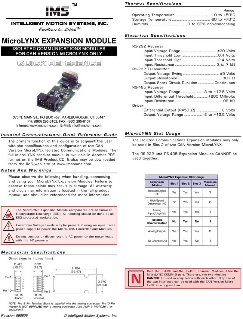
IMS Mforce micro drive Service manual

DRAFT COPY
Hardware
Reference
Excellence in Motion
www.imshome.com
TM
FORCE
MICRO DRIVE
MOTION CONTROL

The information in this book has been carefully checked and is believed to be accurate; however, no responsibility is
assumed for inaccuracies.
Intelligent Motion Systems, Inc., reserves the right to make changes without further notice to any products herein to
improve reliability, function or design. Intelligent Motion Systems, Inc., does not assume any liability arising out of the
application or use of any product or circuit described herein; neither does it convey any license under its patent rights of
others. Intelligent Motion Systems and are trademarks of Intelligent Motion Systems, Inc.
Intelligent Motion Systems, Inc.’s general policy does not recommend the use of its products in life support or aircraft
applications wherein a failure or malfunction of the product may directly threaten life or injury. Per Intelligent Motion
Systems, Inc.’s terms and conditions of sales, the user of Intelligent Motion Systems, Inc., products in life support or
aircraft applications assumes all risks of such use and indemnies Intelligent Motion Systems, Inc., against all damages.
TM
IMS PN MAN-MFIMicro
Revision R112706
Copyright © 2006 Intelligent Motion Systems, Inc., All Rights Reserved
Motion Control MForce MicroDrive Hardware Reference Change Log
Date Revision Changes
11/27/2006 R112706 Initial release.

i
Table of Contents
Getting Started ..................................................................................................................................1-1
Before You Begin....................................................................................................................... 1-1
Tools and Equipment Required................................................................................................. 1-1
Connecting the Power Supply ................................................................................................... 1-1
Connecting Communications ................................................................................................... 1-1
Connecting the Motor .............................................................................................................. 1-1
Minimum Required Connections.............................................................................................. 1-1
Install IMS Terminal Software................................................................................................... 1-2
Establishing Communications................................................................................................... 1-3
Apply Power to the MForce....................................................................................................... 1-4
Testing the MForce ................................................................................................................... 1-4
Make the MForce Move ............................................................................................................ 1-4
Motion Control Example Using Program Mode........................................................................ 1-5
Programming Notes .................................................................................................................. 1-5
Part 1: Hardware Specification
Section 1.1: Motion Control MForce MicroDrive Product Introduction ............................................1-9
Introduction.............................................................................................................................. 1-9
Feature Summary - Standard and Plus2Expanded ..................................................................... 1-9
Section 1.2: Motion Control MForce MicroDrive Detailed Specifications........................................1-11
Electrical Specifications ........................................................................................................... 1-11
Mechanical Specifications........................................................................................................ 1-13
Pin/Wire Assignments and Description................................................................................... 1-13
P1 Connector - I/O and Power Connections...................................................................... 1-13
P1 Connector Options ....................................................................................................... 1-14
P2 Connector - RS-422/485 Communications................................................................... 1-14
P2 Connector Options ....................................................................................................... 1-15
P3 Connector - Motor Phase Connector ............................................................................ 1-15
P3 Connector..................................................................................................................... 1-15
Options and Accessories.......................................................................................................... 1-16
Section 1.3: MForce MicroDrive Plus2Expanded Specifications ......................................................1-17
Electrical Specifications ........................................................................................................... 1-17
Mechanical Specifications........................................................................................................ 1-19
Pin Assignment and Description ............................................................................................. 1-20
P1 Connector - Power and Expanded I/O Configuration ................................................... 1-20
P1 Connector - Power and I/O with Remote Encoder Configuration................................. 1-20
P1 Connector Options ....................................................................................................... 1-21
P2 Connector - RS-422/485 Communications................................................................... 1-21
P2 Connector Options ....................................................................................................... 1-22
P3 Connector - Motor Phase Connector ............................................................................ 1-22
Options and Accessories.......................................................................................................... 1-22
Part 2: Connections and Interface
Section 2.1: Mounting and Connection Recommendations ...............................................................2-3
Mounting Recommendations.................................................................................................... 2-3
DC Power Recommendations ................................................................................................... 2-3
Layout and Interface Guidelines................................................................................................ 2-3
Recommended Wiring ......................................................................................................... 2-4
Recommended Mating Connectors and Pins........................................................................ 2-4
Securing Power Leads and Logic Leads ................................................................................. 2-4
Power Supply Connection......................................................................................................... 2-5
Aux-Logic Supply Connection .................................................................................................. 2-6
Section 2.2: Motor Sizing and Selection ............................................................................................2-7
Selecting a Motor ...................................................................................................................... 2-7
Types and Construction of Stepping Motors ........................................................................ 2-7
Sizing a Motor for Your System ............................................................................................ 2-7
Recommended IMS Motors ..................................................................................................... 2-8

ii
IMS Inside Out Stepper Motors ........................................................................................... 2-9
Motor Wiring.......................................................................................................................... 2-10
Connecting the Motor ............................................................................................................ 2-10
8 Lead Motors ................................................................................................................... 2-10
6 Lead Motors.................................................................................................................... 2-11
4 Lead Motors.................................................................................................................... 2-12
Section 2.3: Interfacing Communications .......................................................................................2-13
Available Communications Cables/Converters ........................................................................ 2-13
Interfacing Single Mode Communications .............................................................................. 2-13
Single Mode Communications Full Duplex (RS-422) ........................................................ 2-13
Single Mode Communications Half Duplex (RS-485) ....................................................... 2-14
Interfacing Party Mode Communications................................................................................ 2-14
Data Cable Termination Resistors....................................................................................... 2-14
MForce Communication Format........................................................................................ 2-15
MForce Response to Echo Mode........................................................................................ 2-15
Using Check Sum............................................................................................................... 2-17
MForce Party Mode Sample Codes..................................................................................... 2-18
MForce Immediate Party Mode Sample Codes................................................................... 2-18
Section 2.4: Interfacing and Using the MFI I/O...............................................................................2-20
The MForce Digital I/O.......................................................................................................... 2-20
Standard I/O Set ................................................................................................................ 2-20
Enhanced I/O Set - MForce Plus2Version .......................................................................... 2-20
Uses of the Digital I/O............................................................................................................ 2-20
MForce Digital Input Functions.............................................................................................. 2-21
Input Functions (I/O Points 1-4, 9-12).............................................................................. 2-21
Input Functions (Points 7 & 8 — Clock Inputs and Point 13 — Capture) ........................ 2-22
Active States Defined.......................................................................................................... 2-22
MForce Digital Output Functions........................................................................................... 2-22
Programmable Output Functions ....................................................................................... 2-22
Output Functions (Points 7 & 8 — Clock Outputs and Point 13 — Trip)......................... 2-23
MForce I/O Ratings ................................................................................................................ 2-24
MForce Standard I/O Connections ......................................................................................... 2-24
MForce Expanded Plus2I/O Connections............................................................................... 2-25
I/O Usage Examples — MForce Standard I/O Set .................................................................. 2-26
Input Interface Example - Switch Input Example (Sinking Input) ...................................... 2-26
Input Interface Example - Switch Input Example (Sourcing Input) .................................... 2-27
Output Interface Example (Sinking Output)...................................................................... 2-28
General Purpose I/O Usage Examples — Enhanced I/O Set ................................................... 2-29
Input Interface Example - Switch Input Example (Sinking Input) ...................................... 2-29
Input Interface Example - Switch Input Example (Sourcing Input) .................................... 2-30
Output Interface Example (Sinking Output)...................................................................... 2-31
Output Interface Example (Sourcing Output).................................................................... 2-32
Dedicated Digital I/O - Enhanced I/O Set.............................................................................. 2-33
Step/Direction/Clock I/O .................................................................................................. 2-33
Capture/Trip ...................................................................................................................... 2-34
Interfacing the Analog Input ................................................................................................... 2-35
Sample Usage ..................................................................................................................... 2-35
Appendices
Appendix A: Recommended Power and Cable Configurations .......................................................... A-3
Example A – Cabling Under 50 Feet, DC Power.......................................................................A-3
Example B – Cabling 50 Feet or Greater, AC Power to Full Wave Bridge ..................................A-3
Example C – Cabling 50 Feet or Greater, AC Power to Power Supply .......................................A-3
Recommended IMS Power Supplies ..........................................................................................A-4
Recommended Power Supply Cabling.......................................................................................A-4
Appendix B: I/O Application Guide.................................................................................................. A-5
Standard I/O Set Interfacing and Application............................................................................A-5
NPN Sinking Input..............................................................................................................A-5
PNP Sourcing Input.............................................................................................................A-6
Sinking Output ....................................................................................................................A-7

iii
Mixed Input/Output Example..............................................................................................A-7
Enhanced I/O Set Interfacing and Application..........................................................................A-8
NPN Sinking Input..............................................................................................................A-8
PNP Sourcing Input.............................................................................................................A-8
Sourcing Output ..................................................................................................................A-8
Mixed Input/Output Example............................................................................................A-10
Interfacing Inputs as a Group Example....................................................................................A-10
Interfacing Outputs as a Group Example.................................................................................A-11
Appendix C: Encoder Options......................................................................................................... A-12
MForce Motion Control Closed Loop Options.......................................................................A-12
Remote Differential Encoder - MForce MicroDrive Plus2..................................................A-12
Encoders Available from IMS..................................................................................................A-12
General Specifications ........................................................................................................A-12
Encoder Signals.......................................................................................................................A-13
Differential Encoder...........................................................................................................A-13
Characteristics ....................................................................................................................A-13
Encoder Cables ......................................................................................................................A-14
Recommended Encoder Mating Connectors ...........................................................................A-14
Appendix D: Optional Cables and Cordsets .................................................................................... A-15
Communications Converter Cables.........................................................................................A-15
USB to 10-Pin IDC (MD-CC400-000).............................................................................A-15
Electrical Specifications ......................................................................................................A-15
Mechanical Specifications...................................................................................................A-15
Installation Procedure for the MX-CC40x-000 .......................................................................A-16
Installing the Cable/VCP Drivers .......................................................................................A-16
Determining the Virtual COM Port (VCP)........................................................................A-18
Prototype Development Cables ...............................................................................................A-18
PD16-1417-FL3 — Power and I/O....................................................................................A-19
Prototype Development Cable PD10-1434-FL3 (All MForce Plus Motion Control)...............A-20
Setup Instructions — Cable #1 ..........................................................................................A-20
Setup Instructions — Cable #2 and Subsequent MDrives ..................................................A-20
Appendix E: IMS Enhanced Torque Stepping Motors...................................................................... A-22
Size 14 Enhanced Torque Stepping Motor...............................................................................A-22
General Specifications ........................................................................................................A-22
Wiring And Connection.....................................................................................................A-22
Mechanical Specifications...................................................................................................A-22
Size 17 Enhanced Torque Stepping Motor...............................................................................A-23
General Specifications ........................................................................................................A-23
Wiring And Connection.....................................................................................................A-23
Mechanical Specifications...................................................................................................A-23
Size 23 Enhanced Torque Stepping Motor...............................................................................A-24
General Specifications ........................................................................................................A-24
Wiring And Connection.....................................................................................................A-24
List of Figures
Figure GS.1: MForce MicroDrive Minumum Required Connections........................................ 1-2
Figure GS.2: Product CD Entry and Installation Screens .......................................................... 1-2
Figure GS.3: IMS Terminal Main Screen................................................................................... 1-3
Figure GS.4: IMS Terminal Preferences Dialog.......................................................................... 1-3
Figure GS.5 MForce MicroDrive Sign-On Message................................................................... 1-4
Figure GS.6: Download the Program ........................................................................................ 1-5
Part 1: Hardware Specification
Figure 1.1.1: MForce MicroDrive with 7-Pin Terminal Strip..................................................... 1-9
Figure 1.1.2: MForce MicroDrive Plus2with Locking Wire Crimp ........................................... 1-9
Figure 1.2.1: Mechanical Specifications................................................................................... 1-13
Figure 1.2.2: P1 Wire Color and Pin Assignment.................................................................... 1-14
Figure 1.2.3: P2 Pin Assignment ............................................................................................. 1-15
Figure 1.2.4: P3 — 4-Pin Locking Wire Crimp Motor Connector.......................................... 1-15

iv
Figure 1.3.1: Mechanical Specifications................................................................................... 1-19
Figure 1.3.2: 16-Pin Wire Crimp Connector P1 Pin Numbers................................................ 1-21
Figure 1.3.3: P2 Pin Assignment ............................................................................................. 1-22
Figure 1.3.4: P3: 4-Pin Locking Wire Crimp Motor Connector.............................................. 1-22
Part 2: Connections and Interface
Figure 2.1.1: MForce MicroDrive Mounting Recommendations............................................... 2-3
Figure 2.1.2: Grounding and Shielding for Logic Connections.................................................. 2-4
Figure 2.1.3: MForce MicroDrive Power Connections .............................................................. 2-5
Figure 2.1.4: Aux-Logic Connection ......................................................................................... 2-6
Figure 2.2.1 A & B: Per Phase Winding Inductance.................................................................. 2-8
Figure 2.2.2: 8 Lead Motor Series Connections....................................................................... 2-10
Figure 2.2.3: 8 Lead Motor Parallel Connections.................................................................... 2-11
Figure 2.2.4: 6 Lead Half Coil (Higher Speed) Motor Connections ....................................... 2-11
Figure 2.2.5: 6 Lead Full Coil (Higher Torque) Motor Connections ...................................... 2-12
Figure 2.2.6: 4 Lead Motor Connections................................................................................. 2-12
Figure 2.3.1: Full Duplex Communications (RS-422)............................................................. 2-13
Figure 2.3.2: Half Duplex 2 Wire Communications (RS-485) ................................................ 2-14
Figure 2.3.3: RS-485 Interface, Multiple MForce System........................................................ 2-15
Figure 2.4.1: Uses for the Digital I/O...................................................................................... 2-20
Figure 2.4.2: Flying Lead I/O Connections ............................................................................. 2-24
Figure 2.4.3: 7-Pin Pluggable Terminal I/O Connections........................................................ 2-24
Figure 2.4.4: Plus 2 I/O Connections - Expanded I/O Configuration..................................... 2-25
Figure 2.4.5: Plus 2 I/O Connections - Closed Loop Configuration........................................ 2-25
Figure 2.4.6: Sinking Input Example using a Push Button Switch ........................................... 2-26
Figure 2.4.7: Sourcing Input Example using a Push Button Switch ......................................... 2-27
Figure 2.4.8: Sinking Output Example.................................................................................... 2-28
Figure 2.4.9: Switch Interface to Input, Sinking ...................................................................... 2-29
Figure 2.4.10 Sourcing Input Example using a Push Button Switch ........................................ 2-30
Figure 2.4.11: Sinking Output Example.................................................................................. 2-31
Figure 2.4.12: Sourcing Output Example................................................................................ 2-32
Figure 2.4.13: MFI Clock Functions....................................................................................... 2-33
Figure 2.4.14: Step Direction I/O Equivalent Circuit.............................................................. 2-33
Figure 2.4.15: Capture/Trip I/O Equivalent Circuit................................................................ 2-34
Figure 2.4.16: Analog Input - Voltage Mode ........................................................................... 2-35
Figure 2.4.17: Analog Input - Current Mode .......................................................................... 2-36
Appendices
Figure A.1: DC Cabling - Under 50 Feet...................................................................................A-3
Figure A.2: DC Cabling - 50 Feet or Greater - AC To Full Wave Bridge Rectifier......................A-3
Figure A.3: AC Cabling - 50 Feet or Greater - AC To Power Supply..........................................A-3
Figure B.1: NPN Interface to an MDI Sinking Input................................................................A-5
Figure B.2: PNP Interface to a Sourcing Input ..........................................................................A-6
Figure B.3: Sinking Output to Relay .........................................................................................A-7
Figure B.4: Mixed Output Example- Standard I/O Set..............................................................A-7
Figure B.5: NPN Sinking Input on an MForce Plus2Motion Control .....................................A-8
Figure B.6: PNP Sourcing Input on an MForce Plus2Motion Control.....................................A-8
Figure B.7: Sourcing Output to Sourcing Input ........................................................................A-9
Figure B.8: Mixed Input/Output Example - Enhanced I/O.....................................................A-10
Figure B.9: TTL Interface to an Input Group..........................................................................A-10
Figure B.10: Outputs Interfaced to LED’s as a Group .............................................................A-11
Figure C.1: Connecting a Remote Encoder .............................................................................A-12
Figure C.2: Differential Encoder Signals..................................................................................A-13
Figure D.1: MD-CC400-000..................................................................................................A-15
Figure D.2: MD-CC400-000 Mechanical Specifications.........................................................A-15
Figure D.3: Hardware Update Wizard.....................................................................................A-16
Figure D.4: Hardware Update Wizard Screen 2.......................................................................A-16
Figure D.5: Hardware Update Wizard Screen 3.......................................................................A-17
Figure D.6: Windows Logo Compatibility Testing ..................................................................A-17
Figure D.7: Hardware Update Wizard Finish Installation........................................................A-17
Figure D.8: Hardware Properties .............................................................................................A-18
Figure D.9: Windows Device Manager....................................................................................A-18
Figure D.10: PD16-1417-FL3 Prototype Development Cable ................................................A-19
Figure D.11: PD10-1434-FL3 ................................................................................................A-21
Figure E.1: Size 14 Wiring and Connection ............................................................................A-22
Figure E.2: Size 14 Mechanical Specifications..........................................................................A-22

v
List of Tables
Table GS.1: Minimum Required Connections .......................................................................... 1-1
Part 1: Hardware Specification
Table 1.2.1: P1 — Pin Assignment, Power and I/O................................................................. 1-13
Table 1.2.2: P2 — Pin Assignment, RS-422/485 Communications......................................... 1-14
Table 1.2.3: P3 — Pin Assignment, Motor Phase Connections ............................................... 1-15
Table 1.3.1: P1 — Pin Assignment, Expanded I/O Configuration .......................................... 1-20
Table 1.3.2: P1 — Pin Assignment, Remote Encoder Configuration....................................... 1-20
Table 1.3.3: P2 — Pin Assignment, RS-422/485 Communications......................................... 1-21
Table 1.3.4: P3 — Pin Assignment, Motor Phase Connections ............................................... 1-22
Part 2: Connections and Interface
Table 2.3.1: MForce Response to Echo Mode - Party and Check Sum are Zero (0)................. 2-16
Table 2.3.2: MForce Response to Echo Mode - Party is One (1) and Check Sum is Zero (0) .. 2-16
Table 2.3.3: MForce Response to Echo Mode - Party is Zero (0) and Check Sum is One (1) .. 2-16
Table 2.3.4: MForce Response to Echo Mode - Party and Check Sum are One (1) ................. 2-17
Table 2.4.1: Programmable Input Functions............................................................................ 2-21
Table 2.4.2: Dedicated Input Functions .................................................................................. 2-22
Table 2.4.3: Programmable Output Functions ........................................................................ 2-23
Table 2.4.4: Dedicated Output Functions ............................................................................... 2-23
Table 2.3.5: MForce I/O and Protection Ratings..................................................................... 2-24
Appendices
Table A.1: Recommended Supply Cables ..................................................................................A-4
Table B.1: Output Bit Weight Examples - Outputs set as a group ...........................................A-11
Table C.1: Available Encoder Line Counts, Part Numbers and Pin Configurations .................A-12
Table D.1: MD-CC400-000 Electrical Specifications..............................................................A-15
Table D.2: PD16-1417-FL3 Wire Color Codes.......................................................................A-19
Table D.3: PD10-1434-FL3 Wire Color Codes.......................................................................A-20
Table E.1: Size 14 General Specifications.................................................................................A-22
Table E.2: Size 17 General Specifications.................................................................................A-23
Table E.3: Size 23 General Specifications.................................................................................A-24

vi
Page Intentionally Left Blank

1-1
Part 1: Hardware Specifications
Ge tt in g St ar te d
Getting Started
Before You Begin
A printed Quick Reference guide designed to help get you connected and communicating with the MForce is
shipped with your product. The following examples will help you get the motor turning for the first time and intro-
duce you to Immediate and Program modes of operation.
Immediate Mode: In Immediate Mode, commands are issued and executed directly to the MForce
MicroDrive by user input into the terminal window of the IMS Terminal Program, shown later in this
section.
Program Mode: Program mode is used to input user programs into the Motion Control MForce
MicroDrive .
Tools and Equipment Required
• Motion Control MForce MicroDrive.
• NEMA Size 14, 17 or 23 frame stepping motor.
• Communications Converter Cable IMS P/N MD-CC400-000 or equivalent (USB to RS-422).
• Product CD or internet access to www.imshome.com.
• A +12 to +48 VDC unregulated power supply.
• Basic tools: wire cutters / strippers / screwdriver.
• 20 AWG wire for power supply.
• 20 AWG wire for motor or optional prototype development cable IMS P/N PD04-MF17-FL3.
• A PC with Windows XP Service Pack 2.
• A free serial communications or USB port.
Connecting the Power Supply
Using 20 AWG wire, connect the DC output of the power supply to the +V input of the MForce MicroDrive.
Connect the power supply ground to the Power Ground pin appropriate for your MForce MicroDrive. See Figure
GS.1.
Connecting Communications
Connect the Host PC to the Motion Control MForce MicroDrive using the IMS Communications Converter
Cable MD-CC400-000 or equivalent.
See Figure GS-1.
Connecting the Motor
In accordance with the motor manufacturer documentation, connect the Motor Phases to the MForce MicroDrive
Connector P4 (Prototype Development Cable IMS P/N PD04-MF17-FL3 recommended).
See Figure GS.1.
Minumum Required Connections
The following Table and Diagram illustrate the minimum required connections to operate the MForce MicroDrive.
Minumum Required Connections
Connector P1 Flying Leads 7-Pin Termnal 16-Pin Wire Crimp
+12 to +48 VDC Red Pin 7 Pin 15
Power Ground Black Pin 6 Pin 16
Connector P2 10 Pin IDC 10 Pin Wire Crimp
TX+ Pin 1 Pin 9
TX – Pin 2 Pin 10
RX + Pin 3 Pin 7
RX - Pin 4 Pin 8
COMM GND Pin 10 Pin 2
Connector P4 4-Pin Locking Wire Crimp
Motor Phase A Pin 1
Motor Phase A Pin 2
Motor Phase B Pin 3
Motor Phase B Pin 4
Table GS.1: Minimum Required Connections
WARNING! Please
ensure that you
read the sections
of the product
manual pertaining to the
MForce MicroDrive model you
purchased in their entirety
prior to placing the unit into full
operation.

1-2 Motion Control MForce MicroDrive Hardware Manual Revision R112706
WARNI N G :
Do not connect
or disconnect
DC input to
the MForce MicroDrive
with power applied!
Disconnect the AC power
side to power down the DC
Supply.
For battery operated
systems, conditioning
measures should be taken
to prevent device damage
caused by in-rush current
draws, transient arcs and
high voltage spikes.
Install IMS Terminal Software
IMS Terminal is an integrated ASCII text editor and terminal emulator designed to easily communicate with and
program IMS Motion Control products. Using this freely provided program will eliminate the added complication
of configuring and using a separate text editor and terminal software.
1. Insert the CD included with the product into the CD Drive of your PC.
If not available, go to http://www.imshome.com/software_interfaces.html.
2. The CD will autostart.
3. Click the Software Button in the top-right navigation Area.
4. Click the IMS Terminal link appropriate to your operating system.
5. Click SETUP in the Setup dialog box and follow the on-screen instructions.
6. Once IMS Terminal is installed, the Communications Settings can be checked and/or set.
Figure GS.2: Product CD Entry and Installation Screens
P3
P1
1 2 3 4
+V (+12 to +48 VDC)
+V Return (Ground)
7-Pin Terminal Connector shown
at P1 - Power and I/O interface.
Other Connector Pin Assignments
detailed with product specifications.
ØA ØBØA ØB
MForce MicroDrive (Front View)
Stepping Motor
Motor Interface Cable
IMS P/N PD04-MF17-FL3
MForce MicroDrive (Side View)
P2
RS-422
Converter
COMM GND
COMM GND
TX+RX+
TX-
RX-
RX+
RX-
TX+
TX-
Host PC
USB/Serial Port
10-Pin IDC Connector shown at P2 -
Communications Interface. Other
connector pin assignments are
detailed with product specifications.
COMM GND is ONLY
to be used for grounding
communications. Grounding
Aux-Logic or any other
device to COMM GND may
damage the MForce!
Communications Cable
IMS P/N MD-CC400-000
or equivalent
Figure GS.1: MForce MicroDrive Minimum Required Connections
Note: Interactive
Tutorials covering
the installation and
use of the IMS Terminal are
located on the IMS Web Site
at http://www.imshome.com/
tutorials.html.

1-3
Part 1: Hardware Specifications
Note: Entering
MForce MicroDrive
commands directly
into the Terminal Window is
called “Immediate Mode”.
The Motion Control MForce
MicroDrive command set is
not case sensitive except for
command DN = < >
Warning: If you
have installed the
MForce MicroDrive
to a load, be sure
the load can safely be moved
before testing.
Tip: Asmall piece of tape on
the motor shaft is a visual aid
to help see the shaft turning.
Establishing Communications
1. Open IMS Terminal by clicking Start>Programs>IMS Terminal>IMS Term. The Program Edit
Window (left) and Terminal Window (right) will be displayed.
2. On the Menu Bar click Edit / Preferences to open the Preferences dialog box.
3. Click on the Comm Settings tab to open the Comm Settings page.
a. Set Scroll Back to desired range of text lines to be displayed.
b. Under Device, confirm MDrive has been selected and also verify the Comm Port being
used. Do not change any other settings. Click “OK”.
Figure GS.3: IMS Terminal Main Screen
Figure GS.4: IMS Terminal Preferences Dialog

1-4 Motion Control MForce MicroDrive Hardware Manual Revision R112706
Apply Power to the Motion Control MForce MicroDrive
1. Verify that all connections have been made, then apply power to the Motion Control MForce
MicroDrive. Click on the Phone icon or the Disconnect status box to establish communications
between IMS Terminal and the MForce MicroDrive. The following sign-on message should appear
in the Terminal Window:
“Copyright 2001-2006 by Intelligent Motion Systems, Inc.”
2. If you can see the sign-on message, then the MForce MicroDrive is properly powered-up and
communicating.
a. If the sign-on message does not appear, try using a software reset. Hold down the “Ctrl” key
and press “C”. If the sign-on message still does not appear, check all connections, as well as all
hardware and software configurations, then start IMS Terminal again.
3. You are now connected and communicating to the Motion Control MForce MicroDrive.
Note: There are indicators at the bottom of the Terminal Window that show whether you are
connected or disconnected, the current Baud Rate, and the type of device (MDrive displayed
when using MForce) for which the IMS Terminal is configured. These three items may be changed
directly from this screen by double clicking on each of them.
Testing the Motion Control MForce MicroDrive
1. Click in the Terminal Window, and type (followed by ENTER):
PR VM
2. The Motion Control MForce MicroDrive will return a value of 768000
3. Type the following in the Terminal Window (followed by ENTER):
VM=360000
PR VM
4. The Motion Control MForce MicroDrive will return a value of 360000
5. Type FD and press ENTER. (FD = Factory Defaults)
“Copyright 2001-2006 by Intelligent Motion Systems, Inc.”
should appear in the Terminal Window within a few seconds.
Make the Motion Control MForce MicroDrive Move
1. Type MR 51200 into the Terminal Window and press ENTER. (MR = Move Relative)
a. With the default settings, the MForce Motion Control should move one revolution in
approximately 0.066 seconds, or at a velocity of 15 revolutions per second.
2. Type SL 102400 and press ENTER. (SL = Slew)
a. With the default settings, the Motion Control MForce MicroDrive should run constantly at a
speed of approximately 2 revolutions per second or 120 revolutions per minute.
3. Type SL 0 and press ENTER. The Motion Control MForce MicroDrive should decelerate to a full
stop.
Figure GS.5 Motion Control MForce MicroDrive Sign-On Message

1-5
Part 1: Hardware Specifications
Motion Control Example Using Program Mode
1. Click on drop-down menu View > New Edit Window to open the Program Edit Window.
2. Type “XYZ Test” into the “Open a New file for editing” dialog box, and click “OK”.
3. Click anywhere within the Program Edit Window, and type (followed by ENTER):
VA LP=0 ‘user variable name LP = start count 0
A=100000 ‘set acceleration to 100000 steps/sec2
D=100000 ‘set deceleration to 100000 steps/sec2
PG 1 ‘enter program mode, start program at address 1
LB AA ‘label program AA
MR 250000 ‘move motor 250000 steps in the positive direction
H ‘hold program execution until motion completes
H 1000 ‘hold 1000 milliseconds
MR –250000 ‘move motor 250000 steps in the negative direction
H ‘hold program execution until motion completes
H 1000 ‘hold 1000 milliseconds
IC LP ‘increment user variable LP
PR ” LP=”,LP;‘print axis position, 4 characters used, the
‘terminal will display LP=1 LP=2 LP=3
BR AA, LP<3 ‘branch to process label AA, if user variable LP< 3
E ‘end program execution
PG ‘exit program, return to immediate mode
4. Type FD in the Terminal Window and press ENTER to clear the MDrive buffer to factory
defaults before downloading any program.
5. Click on drop-down menu Transfer > Download to transfer the program from the Program
Edit Window to the Terminal Window. (Under “Source Type” choose “Edit Window”.)
6. Type EX 1 in the Terminal Window and press ENTER to execute the program.
(EX = Execute at address 1.)
7. The Motion Control MForce MicroDrive will turn the motor 250,000 microsteps in a clockwise
direction, accelerating at 100,000 microsteps per sec2, then decelerating at 100,000 microsteps per
sec2, pausing for 1000 milliseconds, then reversing the sequence in a counterclockwise direction,
repeating the motion cycle 3 times until the program ends.
Programming Notes
The example above demonstrates basic commands that verify that your Motion Control MForce MicroDrive
is communicating with your PC. More complex commands and movement may require that your I/O and/or
Analog Input be interfaced and configured. Refer to the Programming and Software Reference for details.
For more information on Programming and Command Control Sets, refer to the Programming and Soft-
ware Reference Manual available on the your product CD or via the IMS web site at http://www.imshome.
com/manuals.html.
NOTE:Entering
MForce MicroDrive
commands into
the Program Edit
Window, to be edited and
saved, is called “Program
Mode”.
NOTE:The program
can be stopped by
pressing the Escape
Button or by pressing Ctrl+C.
Figure GS.6: Download the Program

This Page Intentionally Left Blank

TM
Excellence in Motion
Section 1.1: Product Introduction
Section 1.2: Standard Specifications
Section 1.3: Expanded Plus2Specifications
Part 1:
Hardware
Specifications
TM
FORCE
MICRO DRIVE
MOTION CONTROL

1-8 Motion Control MForce MicroDrive Hardware Manual Revision R112706
Page Intentionally Left Blank

1-9
Part 1: Hardware Specifications
Section 1.1
Product Introduction
Introduction
The Motion Control MForce MicroDrive offers system
designers a low cost, intelligent motion controller integrated
with a +12 to +48 volt/2A RMS Output Current microstep-
ping drive and Motion Controller.
The unsurpassed smoothness and performance delivered
by the Motion Control MForce MicroDrive are achieved
through IMS's advanced 2nd generation current control.
By applying innovative techniques to control current flow
through the motor, resonance is significantly dampened over
the entire speed range and audible noise is reduced.
The MForce MicroDrive accepts a broad input voltage range
from +12 to +48 VDC, delivering enhanced performance and
speed. Oversized input capacitors are used to minimize power
line surges, reducing problems that can occur with long runs
and multiple drive systems. An extended operating range of
–40° to +85°C provides long life, trouble free service in demanding environments.
Standard features available in the MForce MicroDrive include four +5 to +24 volt general purpose I/O lines, one
10 bit analog input, 0 to 5MHz step clock rate, 20 microstep resolutions up to 51,200 steps per revolution, and full
featured easy-to-program instruction set.
Expanded features in the MForce MicroDrive Plus2
version
include eight +5 to +24 volt general purpose I/O lines and the
capability of electronic gearing by following a rotary or linear axis
at an electronically controlled ratio, or an output clock can be
generated fixed to the internal step clock.
MForce MicroDrive Plus2models are available with optional
closed loop control. This increases functionality by adding stall
detection, position maintenance and find index mark. The closed
loop configuration offers an expanded choice of line counts and
resolutions by interfacing to a remotely mounted user-supplied
external encoder.
The Motion Control MForce MicroDrive communicate over
RS-422/485 which allows for point-to-point or multiple unit
configurations utilizing one communication port. Addressing and
hardware support up to 62 uniquely addressed units communi-
cating over a single line. Baud rate is selectable from 4.8 to 115.2kbps.
Power and signal interface connections are accomplished using 12.0” (30.5cm) flying leads or a 7 position terminal
strip. Plus2versions interface using a pluggable locking wire crimp connector. Motor phases are connected via a
pluggable 4-pin locking wire crimp connector.
The MForce MicroDrive is a compact, powerful and inexpensive solution that will reduce system cost, design and
assembly time for a large range of applications.
Feature Summary – Standard and Plus2Expanded
Standard Features
Highly Integrated Microstepping Driver and Motion Controller
Advanced 2nd Generation Current Control for Exceptional Performance and Smoothness
Single Supply: +12 to +48 VDC
Compact Size: 1.7 x 2.3 x 1.3 inches (42 x 59 x 1.3 mm)
2A RMS/2.8 A Peak (per phase) Output Current
Low Cost
Extremely Compact
Auxiliary Logic Power Supply Input
20 Microstep Resolutions up to 51,200 Steps Per Rev Including: Degrees, Metric, Arc Minutes
Note: The Motion
Control MForce
MicroDrive
is available with CAN
communications. For more
information see IMS Web
Site at www.imshome.com.
Figure 1.1.1: MForce MicroDrive With 1-Pin
Terminal Strip
Figure 1.1.2: MForce MicroDrive Plus2
Wire Crimp

1-10 Motion Control MForce MicroDrive Hardware Manual Revision R112706
Open or Closed Loop Control
Programmable Motor Run and Hold Currents
Four +5 to +24 VDC I/O Lines Accept Sourcing or Sinking Outputs
One 10 Bit Analog Input Selectable: 0 to
+10VDC, 0 to +5VDC, 0-20 mA, 4-20 mA
0 to 5MHz Step Clock Rate Selectable in 0.59Hz Increments
RS-422/485 Communications (Optional CANopen dtails available at www.imshome.com)
62 Software Addresses for Multi-Drop Communications
Simple 1 to 2 Character Instructions
Interface Options:
- 12.0” (30.5cm) Flying Leads
- 7-Pin Pluggable Terminal
Expanded Features – Available only in the Plus2Version
+5 to +24 VDC Tolerant
Sourcing or Sinking, Inputs and Outputs:
8 I/O Points with Electronic Gearing (or)
4 I/O Points with External/Remote Encoder for Closed Loop Control
High Speed Position Capture Input or Trip Output
Pluggable Locking Wire Crimp Interface

1-11
Part 1: Hardware Specifications
SECTION 1.2
Motion Control MForce MicroDrive Specifications
Standard Electrical Specifications
Electrical Specifications
Input Voltage (+V) Range* +12 to +48 VDC
Max Power Supply Current (Per MForce MicroDrive)* 2 Amps
Aux-Logic Input Voltage** +12 to +24 VDC
* Actual Power Supply Current will depend on Voltage and Load.
** Maintains power to control and feedback circuits [only] when input voltage is removed
Output Current
Output Current RMS 2 Amps
Output Current Peak (Per Phase) 2.8 Amps
Environmental Specifications
Heat Sink Temperature -40°C to +85°C
I/O Specifications
General Purpose I/O - Number and Type
Plus (I/O Points 1-4) 4 Sourcing or Sinking Inputs or
4 Sinking Outputs
General Purpose I/O - Electrical
Inputs TTL up to +24 VDC
Sinking Outputs (All) Up to +24 VDC
Output Sink Current (Plus) up to 600 mA (One Channel)
Logic Threshold (Logic 0) < 0.8 VDC
Logic Threshold (Logic 1) > 2.2 VDC
Protection (Sinking) Over Temp, Short Circuit
Protection (Sourcing) Transient Over Voltage, Inductive
Clamp
Analog Input
Resolution 10 Bit
Range (Voltage Mode) 0 to +5 VDC, 0 to +10 VDC
Range (Current Mode) 4 to 20 mA, 0 to 20mA
Clock I/O
Types Step/Direction, Up/Down,
Quadrature
Logic Threshold TTL Input, TTL Output (with 2 kΩ
Load to Ground)
Trip Output/Capture Input
Logic Threshold TTL Input, TTL Output (with 2 kΩ
Load to Ground)
Communications Specifications
Protocol RS-422/RS-485
BAUD Rate 4.8k, 9.6k, 19.2k, 38.4k, 115.2 kbps
WARNING!
The maximum
+48 VDC Input
Voltage of the
MForce MicroDrive series
includes motor Back EMF,
Power Supply Ripple and
High Line.
WARNING! Because the
MForce MicroDrive consists
of two core components,
a drive and a motor, close
attention must be paid to the
thermal environment where
the device is used. See
Thermal Specications.

1-12 Motion Control MForce MicroDrive Hardware Manual Revision R112706
Motion Specifications
Microstep Resolution - Open Loop
Number of Resolutions 20
Available Microsteps Per Revolution
200 400 800 1000 1600 2000 3200 5000 6400 10000
12800 20000 25000 25600 40000 50000 21500 360001216002254003
1=0.01 deg/µstep 2=1 arc minute/µstep 3=0.001 mm/µstep
Counters
Counter 1 (C1) Type Position
Counter 2 (C2) Type Encoder
Resolution 32 Bits
Maximum Edge Rate 5 MHz
Velocity
Range ±5,000,000 Steps/Sec.
Resolution 0.5961 Steps/Sec.
Acceleration/Deceleration
Range 1.5 x 10⁹Steps/Sec.2
Resolution 90.9 Steps/Sec.2
* Microstep Resolution must be set to 2x the Encoder Counts/Rev minimum.
Software Specifications
Program Storage Type/Size Flash/6384 Bytes
User Registers (4) 32 Bit
User Program Labels and Variables 192
Math, Logic and Conditional
Functions +, -, x, ÷, <, >, =, ≤, ≥, AND, OR, XOR, NOT
Branch Functions Branch and Call (Conditional)
Party Mode Addresses 62
Encoder Functions Stall Detect, Position Maintenance, Find Index
Predefined I/O Functions
Input Functions Home, Limit+, Limit -, Go, Stop, Pause, Jog+, Jog-, Analog
Input
Output Functions Moving, Fault, Stall, Velocity Changing
Trip Functions Trip on Input, Trip on Position, Trip on Time, Trip Capture
Table of contents
Other IMS Computer Hardware manuals