In-situ PXD-261 User manual

Instruction Sheet
Page 1 of 4
Calibration Documentation
Documents provided with the transducer describe In-Situ’s calibra-
tion process and list the transducer’s calibration coefficients (Linear-
ity, Scale, and Offset), which are also printed on the backshell dust cap.
Installation
Installation requires four steps, which may be performed in any
convenient order:
• Attach the cable
• Connect the cable to the data logger
• Install the transducer in the water
• Program the data logger to identify the transducer
Attach the Cable
1Remove the protective caps from the backshell and the Quick-
Connect connector on the cable.
2Slide back the sleeve of the Quick-Connect connector.
3Align the tab in the transducer backshell with the slot inside the
cable connector.
4Slide the two parts together and press tightly. They should slip
together easily, without forcing.
5Tighten the locking sleeve hand-tight.
Pressure Transducers: PXD-261 & PXD-461
The only removable parts of the transducer are the nose cone
and cable. Do not take the body apart, as this may severely
damage the transducer and will void the warranty.
In-Situ’s PXD-261 and PXD-461 are fully submersible pressure
transducers for monitoring pressure or water level. They can be used
with In-Situ’s HERMIT®data loggers to collect fast, accurate time-
drawdown data from pump and slug tests. Small diameter permits
access to 1" wells. Removable nosecone and NPT threading allows
use in piping or conduit. Quick-Connect cable is easy to install, and
long cable lengths do not compromise accuracy.
Your transducer was carefully inspected before shipping and is ready
to operate out of the box. Check for any physical damage during
shipment. Notify In-Situ and file a claim with the carrier if there is
any such damage. If your transducer didn’t come as ordered, please
contact In-Situ immediately.
Operating Principle
A pressure transducer senses changes in pressure, measured in
pounds per square inch (PSI), exerted by a column of water or other
fluid above an internal strain gauge. This is translated electronically
to a 4-20 mA signal sent to a data logger. Software calibration coeffi-
cients unique to each transducer enable the logger to convert the 4-
20 mA output to meaningful results in the desired units.
PSIA and PSIG
PSIA stands for “pounds per square inch absolute,” measured with
respect to zero pressure. PSIA transducers measure all pressure forces
detected by the strain gauge, including atmospheric pressure.
PSIG stands for “pounds per square inch gauge,” measured with
respect to atmospheric pressure. PSIG transducers thus exclude the
atmospheric pressure component.
This difference may be represented by a simple equation:
Pgauge = Pabs - Patmos
Don’t discard the caps. Set them aside for later use to
protect the contacts when the probe and cable are not in
use, and for convenient reference to the coefficients.
Quick-Connect
cable connector
Cable
Stainless steel nose cone,
removable for cleaning or for
installation using NPT threads Backshell
Protective dust cap lists calibration coefficients
Stainless steel body, engraved
with model & serial number
PXD Pressure Transducers
(PXD-461 shown)
Wilt u meer informatie over dit product? Bel ons op 036 - 548 61 80.
Page 2 of 4
Connect to the Data Logger
To connect to In-Situ’s HERMIT data loggers:
1Remove the protective caps from the logger and cable connectors.
2Orient the connector patterns so that the large tab
in the cable connector aligns with the V-shaped
notch in the data logger connector.
3Gently press the connector halves together.
Excessive force should not be required.
4Tighten the connector’s lock ring to establish a tight connection
and water-resistant seal.
Program the Data Logger
The process of collecting data from the PXD series transducers and
In-Situ’s HERMIT data loggers is referred to as “running a test.” This
has three steps:
• Enter the transducer characteristics into the data logger
• Enter the test conditions into the data logger
• When the logger is programmed and the transducer is in place,
the test can be started
How you carry out these steps depends on the model of data logger
you are using. For specific information, please refer to the data logger
Operator’s Manual.
Installation Guidelines
• For best results, install the transducer about an hour prior to test
setup or data collection. This will insure that the transducer is
stabilized to the water temperature and allow time for the cable to
stretch or relax.
• To conserve battery power, don’t put the transducer any deeper
than necessary for the test.
• The transducer will not read past its designated range. If the range
is exceeded, the displayed value will remain constant.
• To verify operation, raise and lower the transducer and check that
readings are reasonable and showing change before collecting
data.
• Be sure that the transducer is attached securely to the wellhead or
other stationary object and will not slip during operation.
• Don’t set a pressure transducer below the level of the pump in a
pumping well. The pressure transients generated by the pump will
cause false level readings. Large pumps can swallow the trans-
ducer and cause permanent damage to both the transducer and
the pump.
• Keep the vent tube in the cable unobstructed. Avoid kinks in the
cable. Minimum recommended bend radius is one inch.
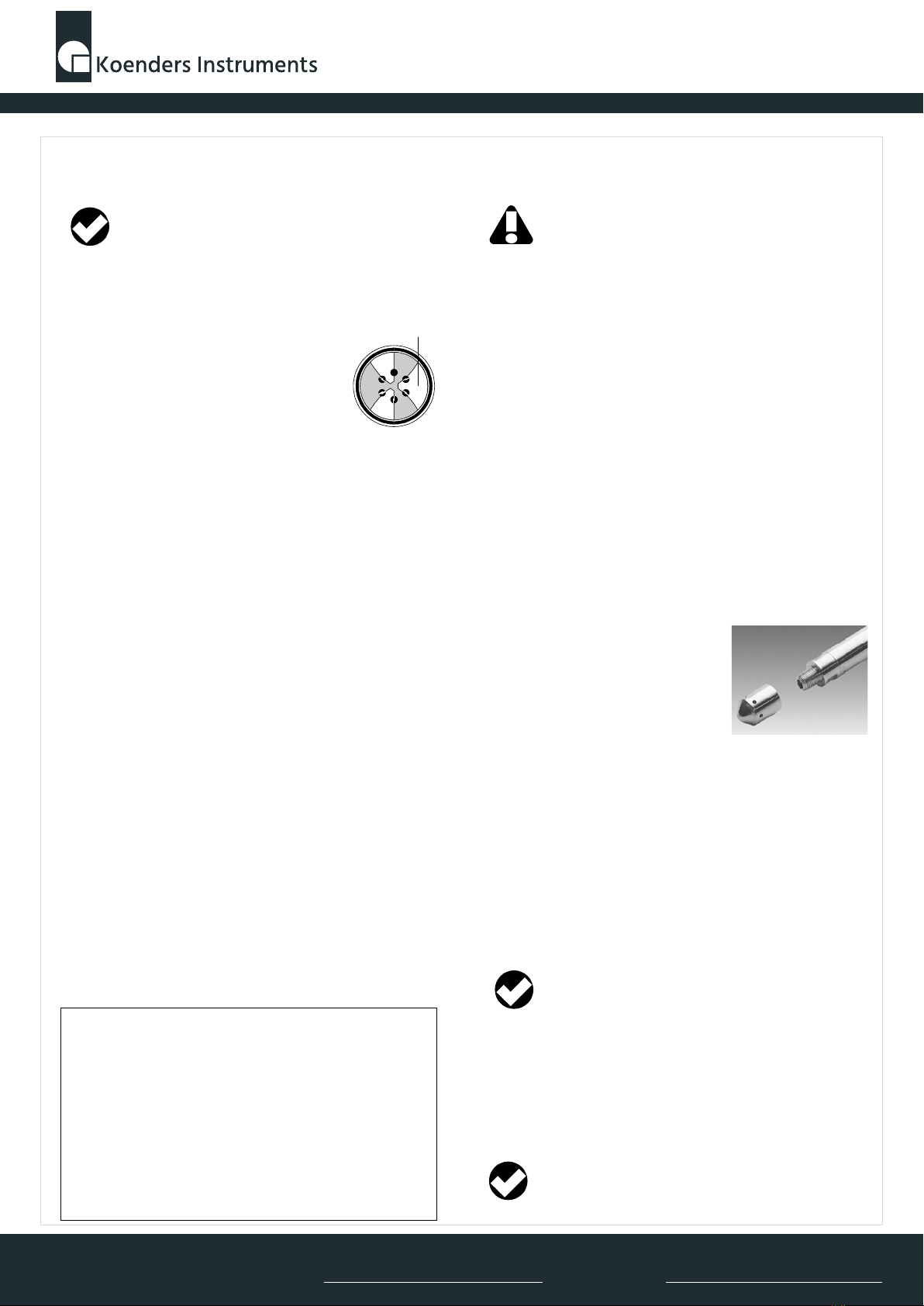
Piping Installations
With the nosecone removed, the transducer
can be installed in any ¼” NPT threaded
pipe to monitor flow. Always remove the
cable before screwing the transducer body
into the NPT.
To install the transducer in a pipe fitting:
1If the cable is attached, remove it. To do so, unscrew the locking
sleeve and gently pull the transducer and cable connector apart.
2Unscrew the nosecone by hand and remove it.
3Using an open end wrench (7/8" for PXD-261, 5/8” for PXD-461)
and the wrench flats on the transducer body, screw the transducer
onto any ¼" NPT threaded nipple, tee, or elbow.
4Reattach the cable.
Accuracy of the electronics may be affected by temperature fluctua-
tions. For long-term tests (several weeks), we recommend you insu-
late the transducer to ensure a thermally stable environment.
Proper operation of a transducer depends upon a clean,
dry connection. Be sure the connectors are clean and
dry before installing them.
Apply your wrench to the wrench flats, not to the spanner
holes at the back end of the transducer. Thread sealing
compound or tape may be used if necessary.
Do not submerge the PXD-261 more than two times its range.
Do not submerge the PXD-461 more than 1.5 times its range.
Overpressuring will permanently offset, damage, or destroy
the transducer.
The pressure reading is calculated by In-Situ’s HERMIT data
loggers using the quadratic formula
P = LX2+ SX + O
where P = Pressure in PSI
X = Normalized* transducer value (0-1)
L = Linearity value from probe data tag
S = Scale value from probe data tag
O = Offset value from probe data tag
*Transducer reading (in milliAmps) minus 4 divided by 16
When replacing the nose cone, first position the o-ring
(PXD-461) or wavy spring washer (PXD-261), if re-
moved, then screw on the nose cone hand-tight.
Large Tab
Wilt u meer informatie over dit product? Bel ons op 036 - 548 61 80.

Page 3 of 4
Using the Transducer with Other Equipment
The transducer provides a current output that is proportional to the
applied pressure. This output is a 4-20 mA change corresponding to a
full-scale change in pressure. The voltage required by the transducer
is 11.6–40 (maximum) VDC.
Any data logger that provides the necessary voltage and can read the
4-20 mA current output can be used with the transducer. To insure
accuracy, power should be applied for a minimum of 50 milliseconds
prior to any reading.
Transducer wiring is shown in the table below by cable type.
Mating connectors must be ordered separately from In-Situ, Inc. A kit
with wiring diagrams is available. Do not use any other type of
connector as this will compromise the integrity of waterproof opera-
tion. Also, remember that the vent tube in the cable must remain
unobstructed to assure that the transducer is insensitive to barometric
pressure changes.
Maintenance
Filter
A small mesh filter protects the pressure sensor from dirt and other
foreign objects. It is held in the end of the NPT threads by a small star
washer and can be seen when the nosecone is removed. The filter
appears opaque when clean. If it becomes clogged with silt, try
flushing it gently with a couple of squeezes from a water bottle. If this
doesn’t do the trick, contact Customer Service.
Nose Cone
If the holes in the nose cone become plugged, take the nose cone off
and clean the holes with a swab or brush. To replace the nose cone
on the PXD-261, first put the wavy spring washer over the threads,
then screw on the nose cone hand-tight.
Cable
The transducer’s Quick-Connect cable connector permits easy cable
removal when changing to a different cable, installing the transducer
in a pipe fitting, or storing the probe. Cable is available in standard
and custom lengths of vented polyurethane or FEP*, or non-vented
HDPE.
Take care to protect the cable from the sharp edges of well casings.
All cables are internally sealed to protect the transducer in the event
that the cable is cut. Don’t attempt to repair, splice, or seal any cuts
without first consulting In-Situ Technical Support personnel.
Vent Tube (Vented Cable)
PSIG pressure sensors are designed to be insensitive to barometric
pressure changes. A vent tube in the cable assures that atmospheric
pressure is the reference pressure to the sensor diaphragm. For
proper operation the vent tube should not be bent, kinked, or
blocked. Such obstructions will cause barometric pressure fluctua-
tions to appear in measurements, and may also introduce large,
varying errors due to thermal expansion and contraction of air
within the vent tube and probe body.
Calibration
Accuracy can be adversely affected by improper care and handling,
exceeding operating pressure and temperature limits, physical
damage or abuse. Annual recalibration is recommended.
Contact In-Situ Customer Service for information on recalibration.
Warranty Provisions
In-Situ Inc. warrants the PXD-261 and PXD-461 for one year from date of
purchase by the end user against defects in materials and workmanship
under normal operating conditions. To exercise this warranty contact Techni-
cal Support at the phone or e-mail address below for a return material
authorization (RMA) and instructions. Complete warranty provisions are
posted on our website at www.In-Situ.com.
In-Situ Inc. does not warrant the transducer against dam-
age caused by use with devices not provided by In-Situ.
Source Double Return Double
Cable Source (+) Return (–) Ground Connector (+) Connector (–)
4-conductor Yellow Brown Shield Yellow & Orange Brown & Red
Non-vented (Pin 6) (Pin 5) (Pin 4)
6-conductor Poly Brown Black Shield Black & White Brown & Red
Vented (RuggedCable™) (Pin 6) (Pin 5) (Pin 4)
6-conductor FEP Yellow Black Shield Yellow & Orange Black & Brown
Vented (RuggedCable™) (Pin 6) (Pin 5) (Pin 4)
Wilt u meer informatie over dit product? Bel ons op 036 - 548 61 80.

Due to continuing product development this information is subject to change without notice. In-Situ, HERMIT, RuggedCable, and the In-Situ logo are
trademarks or registered trademarks of In-Situ Inc. Teflon and Delrin are registered trademarks of E. I. DuPont de Nemours and Company. Viton is a registered
trademark of DuPont Dow Elastomers. Other trademarks are the property of their respective owners. Copyright © 1996 – 2007 by In-Situ Inc. All rights reserved.
1 800 446 7488
(toll-free, US and Canada) or 970 498 1500 www.in-situ.com
Page 4 of 4
Specifications
Wetted materials 316 Stainless steel, Viton®
Transduction principle Integrated silicon strain gauge bridge
Voltage input 11.6 – 40 (absolute maximum) VDC
Signal current 4 – 20 mA (typical throughout pressure range)
Operating temperature 5º to 30ºC (41º to 86ºF)
Storage temperature -40º to 125ºC (-40º to 257ºF)
Min. warmup time 50 milliseconds
PXD-261
Dimensions 0.86” dia., 8.5” long (2.2 x 21.6 cm)
Weight 1 lb. (0.45 kg)
Accuracy ±0.05% of full scale at 15ºC (59ºF)
Ranges Pressure Max. Usable Depth
15 PSIG/PSIA 35 ft /11 m water
20 PSIG/PSIA 46 ft /14 m water
30 PSIG/PSIA 69 ft /21 m water
50 PSIG/PSIA 115 ft /35 m water
100 PSIG/PSIA 231 ft /70 m water
250 PSIG 577 ft /176 m water
Overpressure tolerance 2X full range
PXD-461
Dimensions 0.7” diameter, 8.5” long (1.78 x 21.6 cm)
Weight 0.5 lb (0.22 kg)
Accuracy ±0.04% of full scale at 15ºC (59ºF)
Ranges Pressure Max. Usable Depth
500 PSIA 1153 ft / 352 m water
1000 PSIA 2307 ft / 703 m water
Overpressure tolerance 1.5X full range
Cable
Wetted materials 316 Stainless steel, Viton®
Vented: FEP* or polyurethane
Non-vented: high-density polyethylene (HDPE)
Size 0.25” (6.7 mm) OD nominal
Max. length 4500 ft (1372 m)
Reels Plastic: up to 350 ft (106 m) capacity
Small Steel: up to 450 ft (137 m) capacity
Large Steel: up to 1500 ft (457 m) capacity
0010000 rev. 004 06/07
How to Contact Us
Technical Support: 800 446 7488
Toll-free 24 hours a day in the U.S. and Canada
Address: In-Situ Inc.
221 East Lincoln Ave.
Fort Collins, CO 80524 USA
Phone: 970 498 1500
Fax: 970 498 1598
Internet: www.in-situ.com
e-mail: [email protected]
To Obtain Repair Service (U.S.)
If you suspect the transducer is malfunctioning and repair is re-
quired, you can help assure efficient servicing as follows:
1Call or e-mail In-Situ Technical Support ([email protected]).
Have the product model and serial number handy.
2Be prepared to describe the problem, including how the instru-
ment was being used and the conditions noted at the time of the
malfunction.
3If Tech Support determines that service is needed, they will ask
that your company pre-approve a specified dollar amount for
repair charges. When the pre-approval is received, Tech Support
will assign an RMA (Return Material Authorization) number.
4Clean the probe and cable. Decontaminate thoroughly if it has
been used in a toxic or hazardous environment.
5Pack the transducer in its original shipping box, if possible.
6Mark the RMA number clearly on the outside of the box.
7Send the package, shipping prepaid, to
In-Situ, Inc.
ATTN: Repairs
221 East Lincoln Ave.
Fort Collins, CO 80524
The warranty does not cover damage during transit. In-Situ recom-
mends the customer insure all shipments. Warranty repairs will be
shipped back prepaid.
Outside the U.S.
Contact your international In-Situ distributor for repair and service
information.
** FEP = fluorinated ethylene propylene, the generic equivalent of DuPont Teflon®.
Wilt u meer informatie over dit product? Bel ons op 036 - 548 61 80.
This manual suits for next models
1
Other In-situ Transducer manuals

Popular Transducer manuals by other brands

Ametek
Ametek Gemco 953 Series installation manual

aci
aci ACCESS series Installation & operation instructions

FuehlerSysteme
FuehlerSysteme VMU1/A manual

OHIO SEMITRONICS
OHIO SEMITRONICS DVT Series operating instructions

Dossena
Dossena FL Series quick start guide

Airmar
Airmar M260 Owner's guide & installation instructions


