INA RUE Series Manual

Linear recirculating
roller bearing and
guideway assemblies
Series RUE
Fitting and maintenance manual
MON 30
156 702
D
Rollenumlaufeinheiten
Baureihe RUE
Montage- und Wartungsanleitung
mon_30_deu_gbr.book Seite 1 Mittwoch, 13. Februar 2008 1:06 13
2
DInhaltsverzeichnis Seite
Benötigte Werkzeuge und Hilfsmittel ............................................. 2
Montageplatz/Montagewerkzeuge................................................... 3
Anschlusskonstruktion kontrollieren.............................................. 4
Lieferausführung kontrollieren............................................................ 7
Befestigungsschrauben/Anziehdrehmomente......................... 10
Führungswagen demontieren/montieren.................................... 11
Vormontierte Rollenumlaufeinheiten einbauen....................... 12
Schmierung...................................................................................................... 21
Mindestölmenge bei Inbetriebnahme Qmind/
Ölimpulsmenge Qimp ................................................................................. 26
Erstbefettungsmenge................................................................................. 26
Schmierempfehlung bei Ölimpulsschmierung.......................... 27
Contents Page
Tools and equipment required ............................................................ 2
Fitting area/fitting tools........................................................................... 3
Checking the adjacent construction ................................................ 4
Checking the delivered condition...................................................... 7
Fasteners and tightening torques...................................................... 10
Dismantling and fitting of carriages................................................. 11
Fitting of preassembled linear roller bearing and
guideway assembly .................................................................................... 12
Lubrication........................................................................................................ 21
Minimum oil quantity Qmind/oil impulse quantity Qimp ..... 26
Initial grease quantity ............................................................................... 26
Lubrication recommendation
for oil lubrication with use of metering elements ................... 27
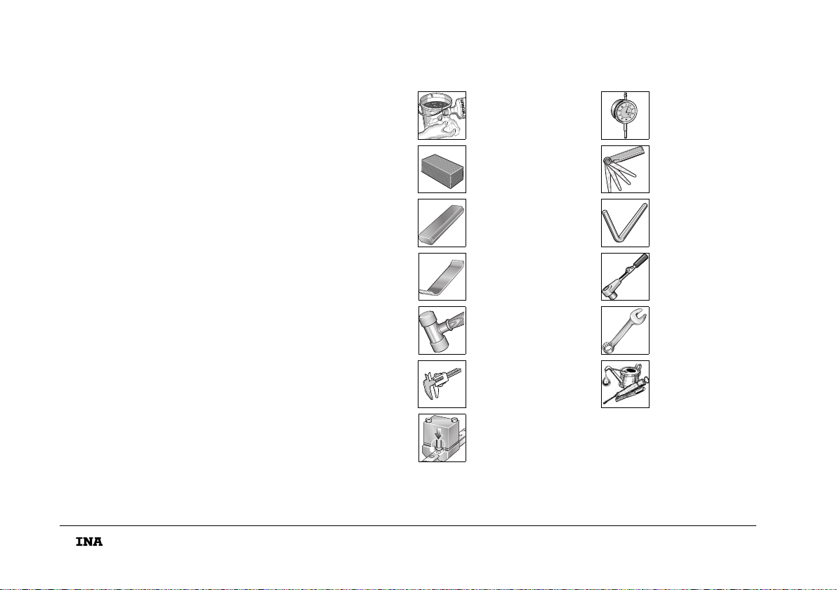
DBenötigte Werkzeuge und Hilfsmittel
Tools and equipment required
Reinigungsmittel
Cleaning agent
Messuhr
Dial gauge
Ölstein
Oil stone
Fühlerlehre
Feeler gauges
Schutzschiene
Dummy guideway
Innensechskant-
schlüssel
Allan key
Federstahlblech
Spring steel strip
Drehmoment-
schlüssel
Torque wrench
Kunststoffhammer
Plastic hammer
Gabelschlüssel
Open-end wrench
Messschieber
Vernier
Schmierung
Lubrication
Montagevorrichtung
Fitting device
mon_30_deu_gbr.book Seite 2 Mittwoch, 13. Februar 2008 1:06 13

3
Diese Anleitung gilt für Rollenumlaufeinheiten RUE!
Führungen nur danach einbauen!
In der Nähe des Montageplatzes nicht mit span-
abhebenden oder stauberzeugenden Maschinen,
Geräten, Anlagen arbeiten!
Verhindern, dass Verunreinigungen/Feuchtigkeit in
die Einheiten gelangen! Sie beeinträchtigen die Funktion
der Elemente erheblich und verringern ihre Gebrauchs-
dauer nachhaltig! Elemente nur mit vorgeschriebenen
Werkzeugen montieren. Ungeeignete oder verschmutzte
Werkzeuge können die Funktion und Gebrauchsdauer
der Führungen erheblich verringern!
DMontageplatz/Montagewerkzeuge
This manual is valid for linear roller bearing and guideway
assemblies RUE. The guidance systems should only be
fitted in accordance with the manual.
Machines, devices or equipment which generate swarf or
dust must not be used in the immediate vicinity of
the fitting area.
It must be ensured that contaminants or moisture cannot
penetrate the units. These impair the function and
operating life of the elements considerably.
Elements should only be fitted using the tools specified
and in a clean condition. Unsuitable or contaminated
tools can reduce the function and operating life of
the elements considerably.
Fitting area/fitting tools
156 703
mon_30_deu_gbr.book Seite 3 Mittwoch, 13. Februar 2008 1:06 13
4
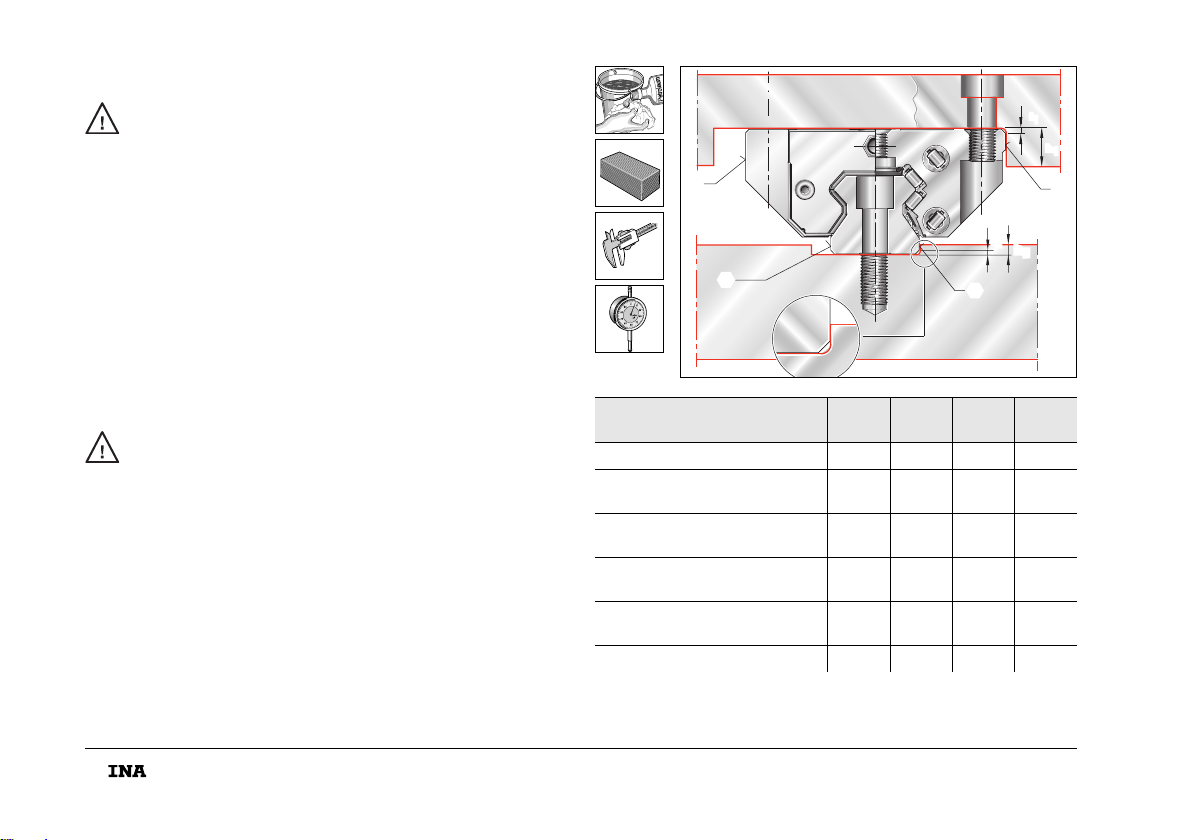
Die Anschlusskonstruktion muss sauber sein!
Schmutz beeinträchtigt die Genauigkeit und
verringert die Gebrauchsdauer der Umlaufeinheit!
■Bohrungen und Anschlagkanten auf Gratbildung
überprüfen; Grat mit Ölstein entfernen.
■Anschlaghöhen und Eckenradien nach Bild und Tabelle
überprüfen; Abweichungen korrigieren.
■Anschlagseite und Beschriftungsseite müssen sich
gegenüber liegen.
DAnschlusskonstruktion kontrollieren
The adjacent construction must be clean.
Contamination impairs the accuracy and operating life
of the recirculating unit.
■Check the holes and locating edges for burrs;
remove any burrs using an oilstone.
■Check the locating heights and corner radii in accordance
with the figure and table; correct any deviations.
■The locating face and marked face must be on
opposing sides.
Checking the adjacent construction RUE25-D (-L, -H, -HL)
RUE..-E (-L, -H, -HL, -KT-L, -KT-HL) h1h2
max. r1
max. r2
max.
RUE25-D (-L, -H, -HL) 7,5 4,5 0,8 0,3
RUE35-E (-L, -H, -HL)
RUE35-E-KT (-L, -HL) 8610,8
RUE45-E (-L, -H, -HL)
RUE45-E-KT (-L, -HL) 10 8 1 0,8
RUE55-E (-L, -H, -HL)
RUE55-E-KT (-L, -HL) 12 9,5 1 0,8
RUE65-E (-L, -H, -HL)
RUE65-E-KT (-L, -HL) 15 10,5 1 0,8
RUE100-E-L 25 13 1 0,8
r
h
1
1
h
2
r
2
156 704
mon_30_deu_gbr.book Seite 4 Mittwoch, 13. Februar 2008 1:06 13
5
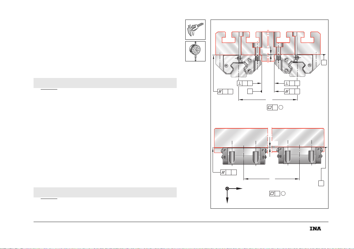
■Form-/Lagetoleranzen der Anschraub- und Anschlagflächen
nach Bild kontrollieren; Flächen gegebenenfalls bearbeiten
– Parallelitätstoleranz t, Seite 6.
■Höhenversatz H(m) der Auflageflächen ermitteln.
■Höhenversatz nach Gleichung berechnen, mit Messwert
vergleichen; Flächen gegebenenfalls bearbeiten.
b (mm) ist Mittenabstand.
Nicht konvex (für alle Bearbeitungsflächen).
DAnschlusskonstruktion kontrollieren
H 0,075 · b=
■Check the geometrical tolerances of the screw mounting
and locating surfaces in accordance with the figure;
machine the surfaces if necessary
– Parallelism tolerance t, page 6.
■Determine the height offset H(m) of the support surfaces.
■Calculate the height offset according to the formula and
compare it with the measured value; machine the surfaces
if necessary.
b (mm) is the centre distance.
Not convex (for all machined surfaces).
Checking the adjacent construction
H 0,075 · b=
A
A
A
BB
A
b
A
A
b
zx
y
t
t
t
t
t
t
t
H
H
1
1
156 705
mon_30_deu_gbr.book Seite 5 Mittwoch, 13. Februar 2008 1:06 13
This manual suits for next models
25
Table of contents
Other INA Industrial Equipment manuals


