INA KUE Series Manual
Two row linear
recirculating ball bearing and
guideway assemblies
Series KUE
Fitting and maintenance manual
MON 31
zx
y
A
B
t
t
MA
204 003
D
Zweireihige
Kugelumlaufeinheiten
Baureihe KUE
Montage- und Wartungsanleitung
mon_31_deu_gbr.book Seite 1 Donnerstag, 24. Februar 2005 10:02 10
2
DInhaltsverzeichnis Seite
Benötigte Werkzeuge und Hilfsmittel............................................ 2
Montageplatz/Montagewerkzeuge................................................. 3
Anschlusskonstruktion kontrollieren .............................................. 4
Lieferausführung kontrollieren............................................................ 7
Befestigungsschrauben/Anziehdrehmomente........................ 9
Führungswagen demontieren/montieren ................................... 10
Vormontierte Kugelumlaufeinheiten einbauen......................... 11
Schmierung.................................................................................................... 17
Mindestölmenge bei Inbetriebnahme Qmind/
Ölimpulsmenge Qimp................................................................................ 18
Erstbefettungsmenge .............................................................................. 18
Contents Page
Tools and equipment required ........................................................... 2
Fitting area/fitting tools............................................................................ 3
Checking the adjacent construction.............................................. 4
Checking the delivered condition .................................................... 7
Fasteners and tightening torques.................................................... 9
Dismantling and fitting of carriages ................................................ 10
Fitting of preassembled linear ball bearing and
guideway assembly................................................................................... 11
Lubrication ...................................................................................................... 17
Minimum oil quantity Qmin/oil impulse quantity Qimp.......... 18
Initial grease quantity................................................................................ 18
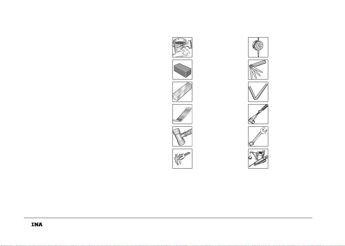
DBenötigte Werkzeuge und Hilfsmittel
Tools and equipment required
Reinigungsmittel
Cleaning agent
Messuhr
Dial gauge
Ölstein
Oil stone
Fühlerlehre
Feeler gauges
KUE-Schutzschiene
KUE dummy guideway
Innensechskant-
schlüssel
Allan key
Federstahlblech
Spring steel strip
Drehmoment-
schlüssel
Torque wrench
Kunststoffhammer
Plastic hammer
Gabelschlüssel
Open-end wrench
Messschieber
Vernier
Schmierung
Lubrication
mon_31_deu_gbr.book Seite 2 Donnerstag, 24. Februar 2005 10:02 10
3
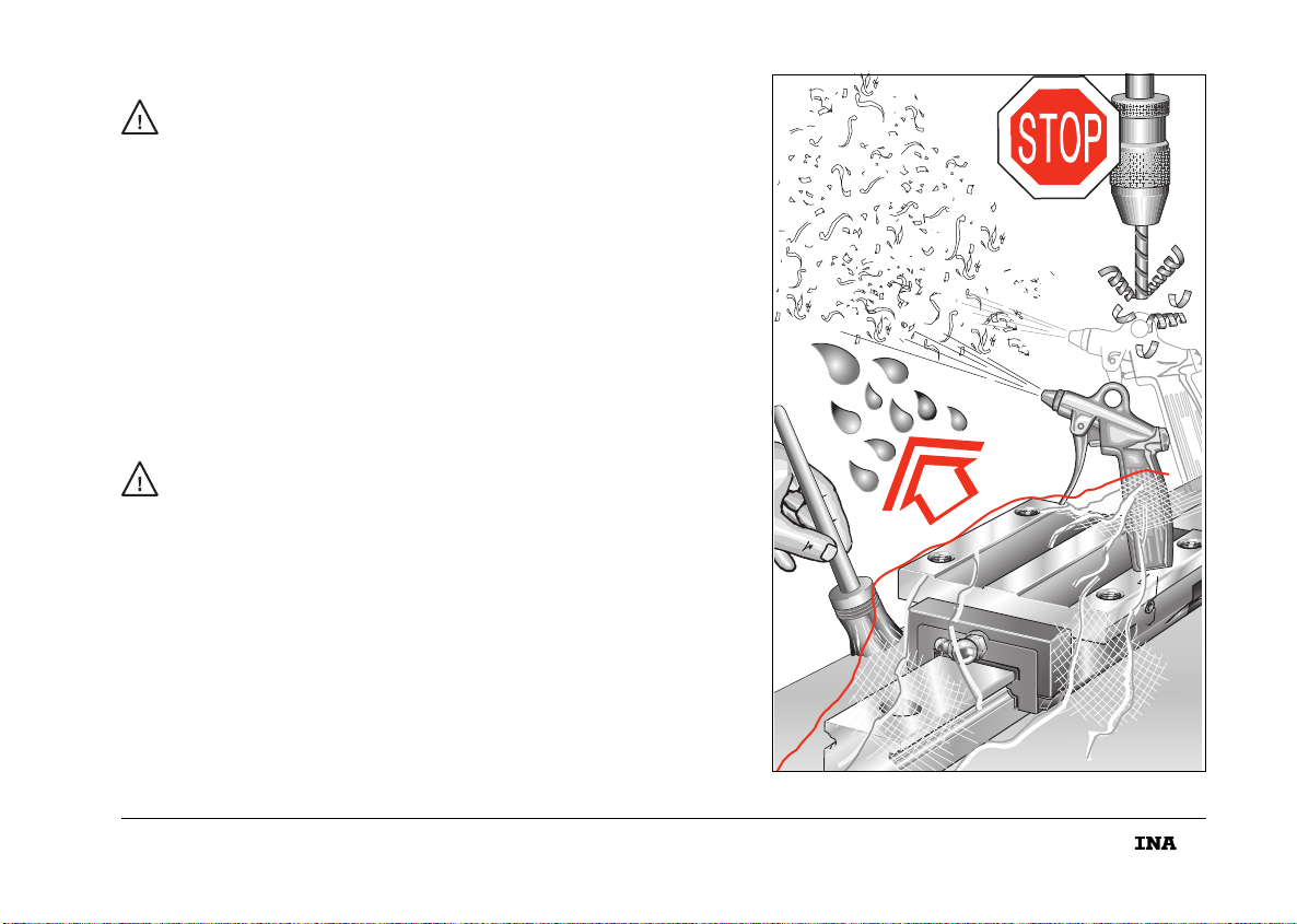
Diese Anleitung gilt für Kugelumlaufeinheiten KUE!
Führungen nur danach einbauen!
In der Nähe des Montageplatzes nicht mit span-
abhebenden oder stauberzeugenden Maschinen,
Geräten, Anlagen arbeiten!
Verhindern, dass Verunreinigungen/Feuchtigkeit in
die Einheiten gelangen! Sie beeinträchtigen die Funktion
der Elemente erheblich und verringern ihre Gebrauchs-
dauer nachhaltig! Elemente nur mit vorgeschriebenen
Werkzeugen montieren. Ungeeignete oder verschmutzte
Werkzeuge können die Funktion und Gebrauchsdauer
der Führungen erheblich verringern!
DMontageplatz/Montagewerkzeuge
This manual is valid for linear ball bearing and guideway
assemblies KUE. The guidance systems should only be
fitted in accordance with the manual.
Machines, devices or equipment which generate swarf or
dust must not be used in the immediate vicinity of
the fitting area.
It must be ensured that contaminants or moisture cannot
penetrate the units. These impair the function and
operating life of the elements considerably.
Elements should only be fitted using the tools specified
and in a clean condition. Unsuitable or contaminated
tools can reduce the function and operating life of
the elements considerably.
Fitting area/fitting tools
204 004
mon_31_deu_gbr.book Seite 3 Donnerstag, 24. Februar 2005 10:02 10
4
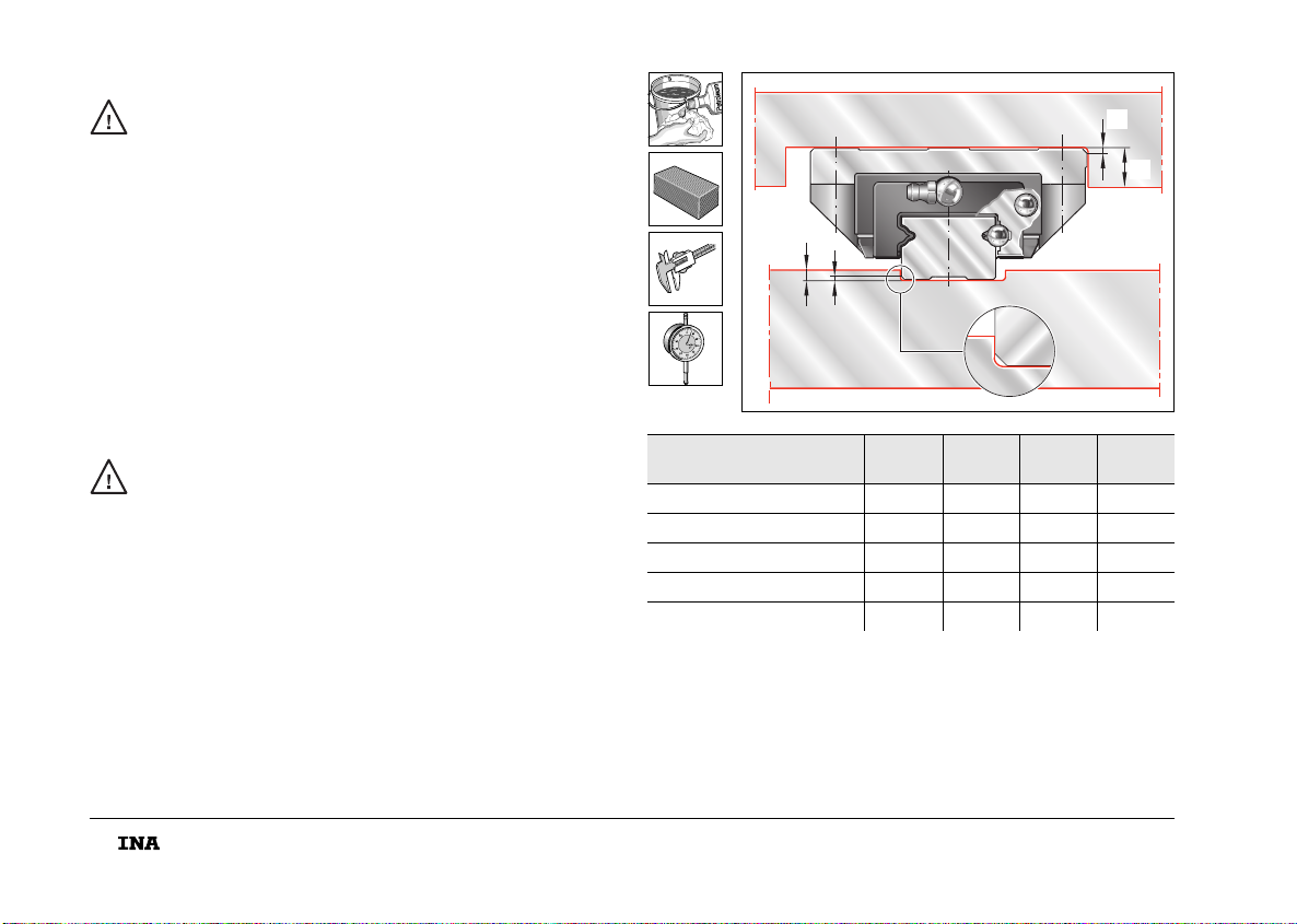
Die Anschlusskonstruktion muss sauber sein!
Schmutz beeinträchtigt die Genauigkeit und
verringert die Gebrauchsdauer der Umlaufeinheit!
■Bohrungen und Anschlagkanten auf Gratbildung
überprüfen; Grat mit Ölstein entfernen.
■Anschlaghöhen und Eckenradien nach Bild und Tabelle
überprüfen; Abweichungen korrigieren.
DAnschlusskonstruktion kontrollieren
The adjacent construction must be clean.
Contamination impairs the accuracy and operating life
of the recirculating unit.
■Check the holes and locating edges for burrs;
remove any burrs using an oilstone.
■Check the locating heights and corner radii in accordance
with the figure and table; correct any deviations.
Checking the adjacent construction KUE..(H) h1h2
max. r1
max. r2
max.
KUE 15 (H) 4,5 3,5 1 0,5
KUE 20 (H) 5410,5
KUE 25 (H) 54,510,8
KUE 30 (H) 6510,8
KUE 35 (H) 6,5610,8
r
h2
2
h1
r1
205 005
mon_31_deu_gbr.book Seite 4 Donnerstag, 24. Februar 2005 10:02 10
5
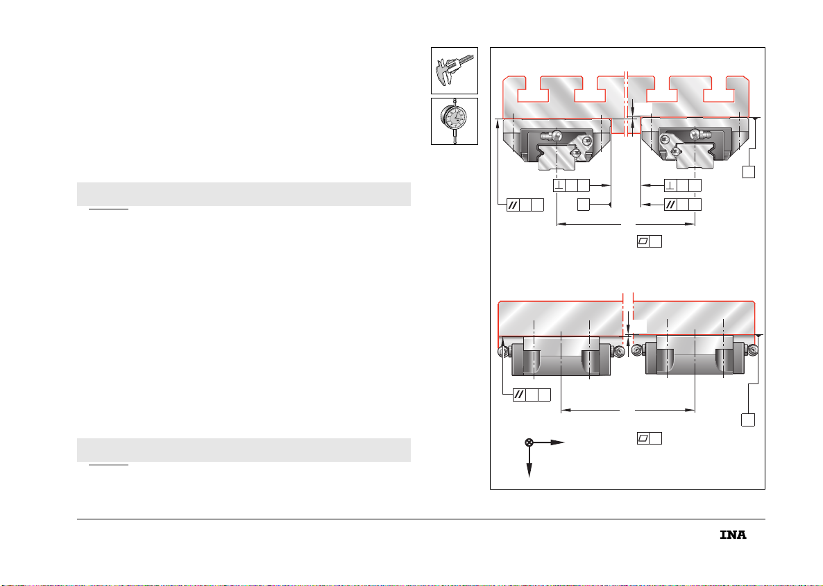
■Form-/Lagetoleranzen der Anschraub- und Anschlagflächen
nach Bild kontrollieren; Flächen ggf. bearbeiten
– Parallelitätstoleranz t siehe Seite 6.
■Höhenversatz ⌬H(m) der Auflageflächen ermitteln.
■Höhenversatz nach Gleichung berechnen, mit Messwert
vergleichen; Flächen ggf. bearbeiten.
b (mm) ist Mittenabstand.
1) Nicht konvex (für alle Bearbeitungsflächen).
DAnschlusskonstruktion kontrollieren
⌬
H0,2b⋅=
■Check the geometrical tolerances of the screw mounting
and locating surfaces in accordance with the figure;
machine the surfaces if necessary
– Parallelism tolerance t: see page 6.
■Determine the height offset ⌬H(m) of the support surfaces.
■Calculate the height offset according to the formula and
compare it with the measured value; machine the surfaces
if necessary.
b (mm) is the centre distance.
1) Not convex (for all machined surfaces).
Checking the adjacent construction
⌬
H0,2b⋅=
t
zx
y
⌬H
A
A
A
BB
A
b
t
t
t
t
A
A
b
t
t
⌬H
204 006
mon_31_deu_gbr.book Seite 5 Donnerstag, 24. Februar 2005 10:02 10
6
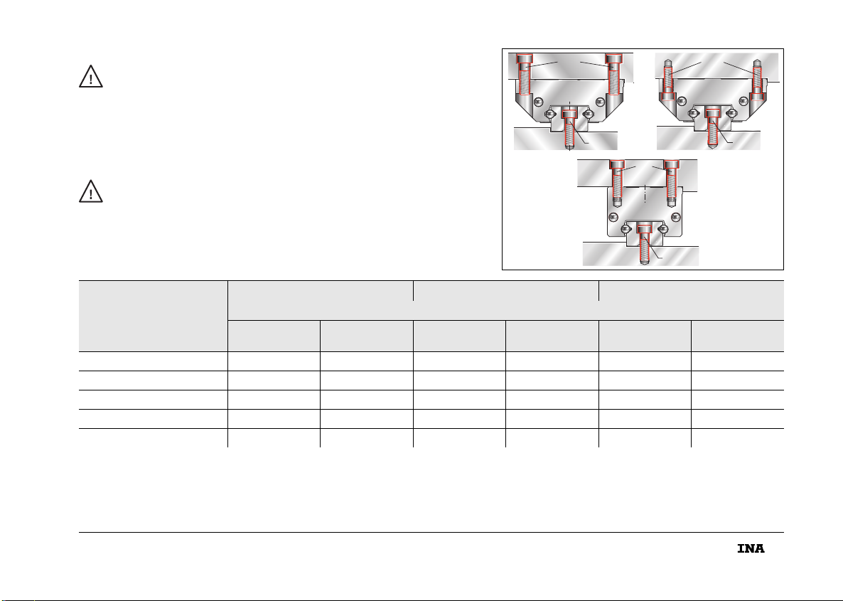
Hat das Maschinenbett zwei definierte Anschlagflächen,
Parallelität der Anschlagflächen überprüfen.
Bei Höchstwerten nach Tabelle kann der Verschiebe-
widerstand steigen!
■Parallelität der Anschlagflächen nach Bild und Tabelle
kontrollieren.
■Die Parallelitätstoleranz hängt von der Vorspannungs-
klasse (V0 und V1) ab. Bei Abweichung Auflage- und
Anschlagflächen für die Schienen an der Anschluss-
konstruktion nacharbeiten.
1) Nicht konvex (für alle Bearbeitungsflächen).
DAnschlusskonstruktion kontrollieren
If the machine bed has two defined locating surfaces,
check the parallelism of the locating surfaces.
If the highest values according to the table are reached,
the displacement resistance may increase.
■Check the parallelism of the locating surfaces in accordance
with the figure and table.
■The parallelism tolerance depends on the preload class
(V0 and V1). If there are deviations, rework the support and
locating surfaces for the guideways on the adjacent
construction.
1) Not convex (for all machined surfaces).
Checking the adjacent construction TKD V0
t
m
V1
t
m
TKD 15 13 10
TKD 20 18 12
TKD 25 22 14
TKD 30 26 17
TKD 35 30 20
xz
y
⌬H
C
t
b
tC
204 007
mon_31_deu_gbr.book Seite 6 Donnerstag, 24. Februar 2005 10:02 10
7
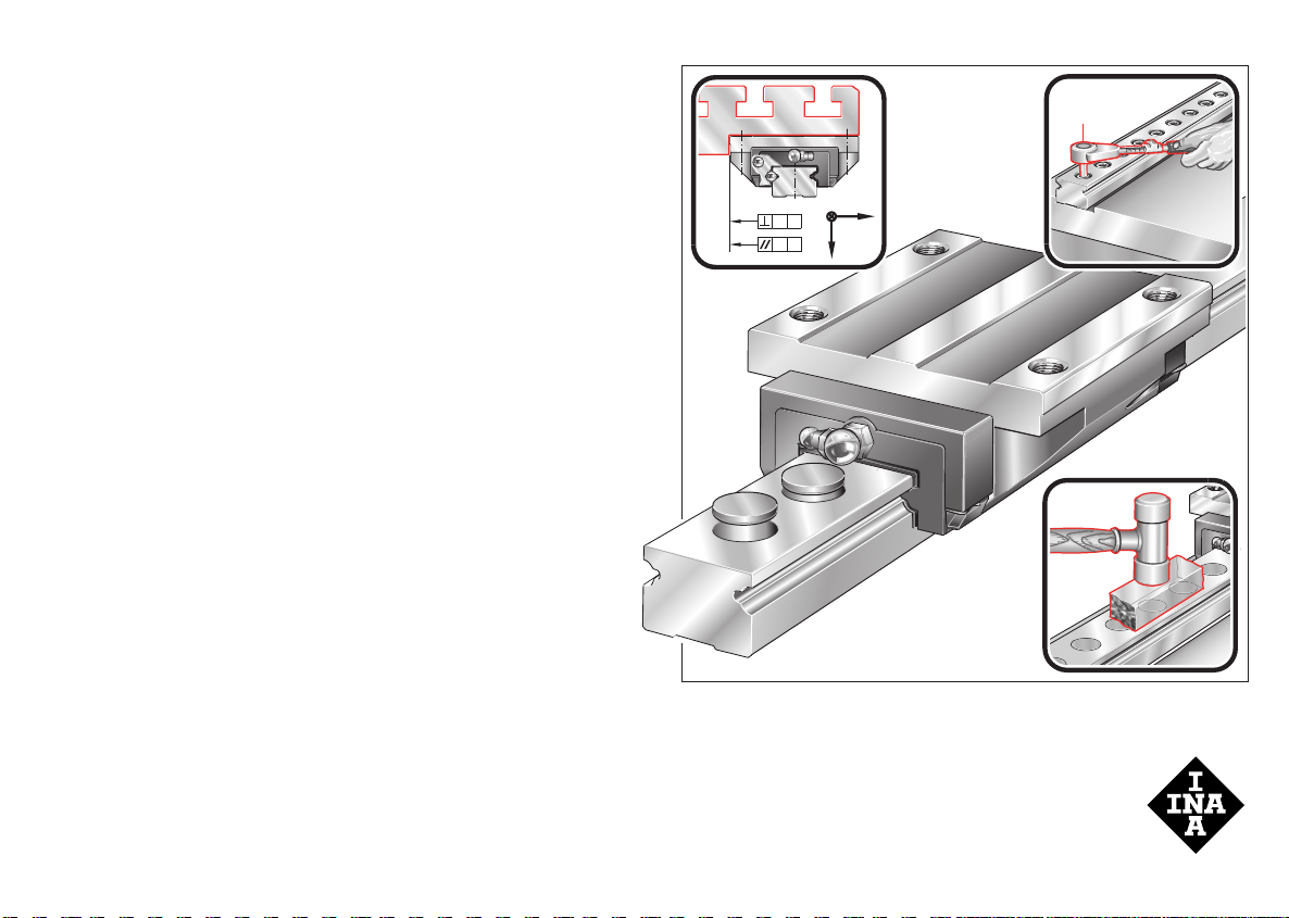
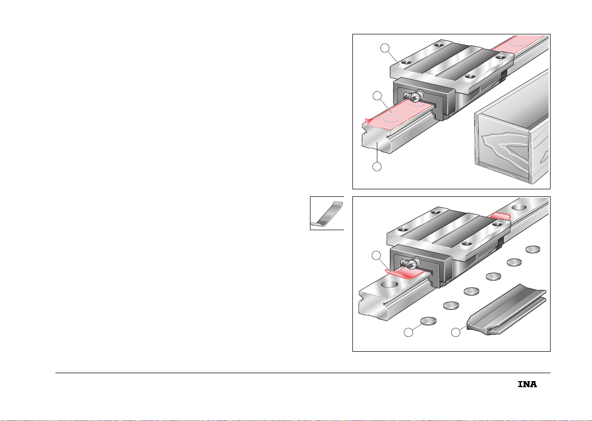
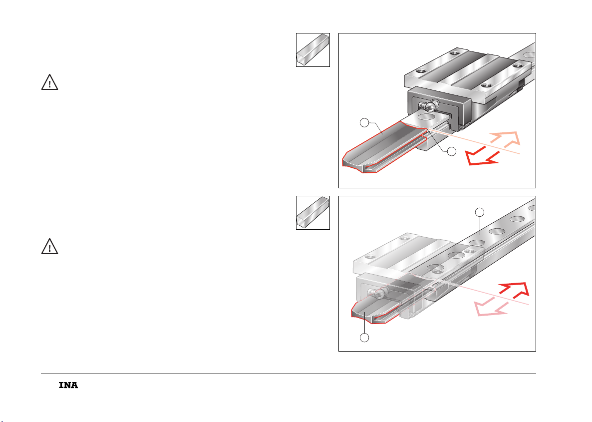
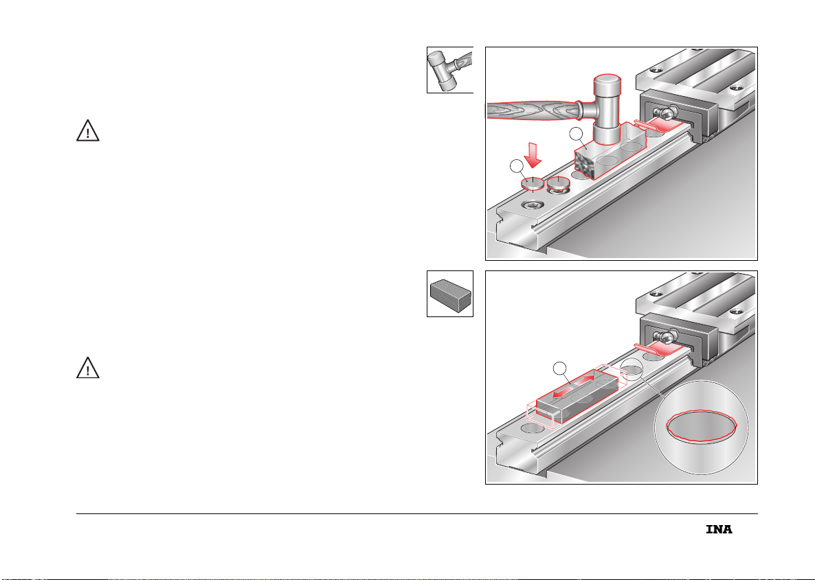
Der Führungswagen ist auf der Führungsschiene .
Schiene und Wagen sind konserviert. Einheiten erst direkt vor
dem Einbau aus der Verpackung nehmen.
Klebeband deckt die scharfkantigen Senkungen ab
(Verletzungsgefahr!). Band erst beim Einbau der Einheiten
entfernen.
Verschlusskappen und Schutzschiene liegen bei.
Wagen nicht über unverschlossene Senkungen führen!
Muss der Wagen bewegt werden, zum Schutz der Dichtlippen
Federstahlblech (0,2 mm dick) zwischen Schienen-
oberfläche und Führungswagen schieben. Enden vor und hinter
dem Wagen leicht nach oben biegen. Das Federstahlblech
muss vom Kunden angefertigt werden.
DLieferausführung kontrollieren
The carriage is located on the guideway . The guideway
and carriage are supplied coated with a preservative.
Units should not be removed from their packaging until
immediately before assembly.
The sharp-edged counterbores (risk of injury) are covered by
an adhesive strip . The strip should only be removed when
the units are fitted.
Closing plugs and a dummy guideway are supplied.
Do not move the carriage over holes that have not been closed
off. If the carriage must be moved, protect the seal lips
by sliding a spring steel strip (0,2 mm thick) between
the guideway surface and the carriage.
Bend the ends up slightly at both ends of the carriage.
The spring steel strip must be produced by the customer.
Checking the delivered condition
3
1
2
204 008
6
4 5
204 009
mon_31_deu_gbr.book Seite 7 Donnerstag, 24. Februar 2005 10:02 10
8
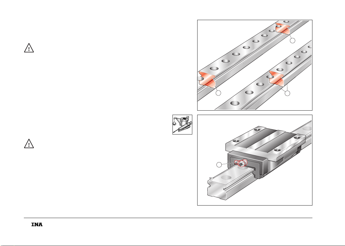
Mehrteilige Führungsschienen sind zusammen verpackt.
Die Trennstellen , , sind fortlaufend gekennzeichnet.
Führungsschienen so montieren, dass die gleichen
Nummern und Buchstaben aneinander stoßen!
Führungswagen haben Schmiernippel nach DIN 71412,
Form A .
Abhängig von der Schmierungsart:
■Wagen mit Mindestölmenge schmieren bzw.
mit Erstbefettungsmenge füllen.
■Schienen ölen/fetten (Öl-, Fettmengen Tabelle, Seite 18).
DLieferausführung kontrollieren
Multi-piece guideways are packed in sets.
The joints , , are numbered consecutively.
Mount the guideways such that the numbers and letters
adjacent to each other are identical.
Carriages have lubrication nipples in accordance with
DIN 71412, type A .
Depending on the type of lubrication:
■lubricate the carriages with the minimum oil quantity or
with the initial grease quantity
■oil or grease the guideways (oil and grease quantities in
accordance with table, page 18).
Checking the delivered condition
1A
1A
1A
1A
1
2
1B
1B
1B
1B
2A
2A
2A
2A
3
204 010
4
204 011
mon_31_deu_gbr.book Seite 8 Donnerstag, 24. Februar 2005 10:02 10
9
Einheiten nur mit vorgeschriebenen Schrauben
befestigen (Tabelle)!
Abmessung, Anzahl, Festigkeitsklasse, Anzieh-
drehmoment unbedingt einhalten (Bild, Tabelle)!
DBefestigungsschrauben/Anziehdrehmomente
Units must only be located using the screws specified
(table).
It is absolutely essential that the correct size, quantity,
grade and tightening torque are used (figure, table).
Fasteners and tightening torques
G
2
K
1
K
1
K
1
K
3
G
2
204 012
KUE..(H) G2K1K3
DIN ISO 4 762-12.9
MA
Nm MA
Nm MA
Nm
KUE 15 / KUE 15 H M 5 / M4 5,8 / 5 M4 / M4 5 / 5 M4 / – 5
KUE 20 / KUE 20 H M 6 / M5 10,8 / 10 M5 / M5 10 / 10 M5 / – 10
KUE 25 / KUE 25 H M 8 / M6 24,8 / 17 M6 / M6 17 / 17 M6 / – 17
KUE 30 / KUE 30 H M10 / M8 41,8 / 41 M8 / M8 41 / 41 M8 / – 41
KUE 35 / KUE 35 H M10 / M8 41,8 / 41 M8 / M8 41 / 41 M8 / – 41
mon_31_deu_gbr.book Seite 9 Donnerstag, 24. Februar 2005 10:02 10
10
Die Schutzschiene verhindert Schäden am Wälzkörpersatz,
wenn der Wagen von der Schiene getrennt ist.
Wagen – nur wenn notwendig – unter Verwendung der
Schutzschiene von der bzw. auf die Schiene schieben!
■Bei montiertem Wagen Schutzschiene vor die
Führungschiene setzen und den Wagen auf die Schutz-
schiene schieben. Schiene im Wagen lassen.
■Bei demontiertem Wagen Schiene mit Wagen vor die
Schiene setzen/Wagen auf die Schiene schieben.
DFührungswagen demontieren/montieren
The dummy guideway prevents damage to the rolling
element set while the carriage is separate from the guideway.
The carriage must only be slid on or off the guideway
if necessary: if so, the dummy guideway must always
be used.
■If the carriage is already on the guideway, position
the dummy guideway against the end of the guideway
and slide the carriage onto the dummy guideway.
Leave the guideway in the carriage.
■If the carriage is separate from the guideway, position
the dummy guideway with the carriage against the end
of the guideway and slide the carriage onto the guideway.
Dismantling and fitting of carriages
2
1
204 013
2
1
204 014
mon_31_deu_gbr.book Seite 10 Donnerstag, 24. Februar 2005 10:02 10
11
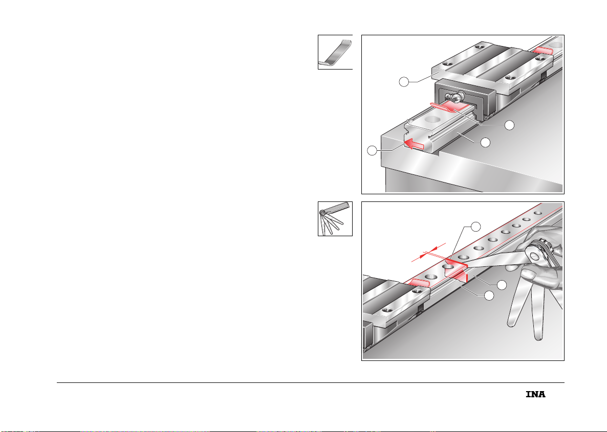
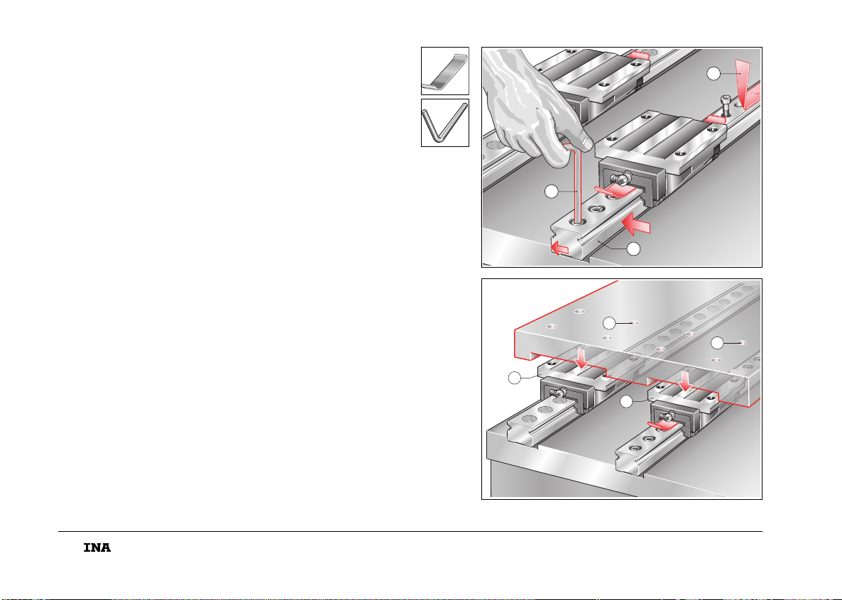
Der Wagen ist auf der Führungsschiene , Befestigung vom
Schlitten aus. Nicht vormontierte Einheit analog einbauen.
■Dichtlippen mit Federstahlblech schützen (siehe Seite 7).
■Umlaufeinheit der Referenzseite auf das Maschinenbett
setzen.
Bei mehrteiligen Schienen Reihenfolge der Schienen ,
beachten (Seite 8)!
Der stirnseitige Spalt muss ⬍0,05 mm sein!
DVormontierte Kugelumlaufeinheiten einbauen
The carriage is on the guideway and is mounted on
the table. A unit that is not preassembled should be fitted in
a similar way.
■Protect the seal lips using a spring steel strip
(see page 7).
■Position the recirculating unit with its datum side on
the machine bed.
If multi-piece guideways are used, note the sequence of
the guideways , (page 8).
The gap at the end face must be smaller than 0,05 mm.
Fitting of preassembled linear ball bearing and
guideway assembly
1
2
3
4
204 015
1A
1A
1A
1A
< 0,05
5
6
7
204 016
mon_31_deu_gbr.book Seite 11 Donnerstag, 24. Februar 2005 10:02 10
12
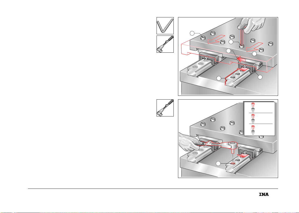
■Klebeband bohrungsweise abziehen, Schrauben in
die Bohrungen setzen und handfest anziehen.
■Führungsschiene gegen Anschlagfläche drücken (Pfeile).
■Schrauben in der Reihenfolge des Anziehschemas
anziehen . Anziehdrehmoment MAsiehe Tabelle, Seite 9.
DVormontierte Kugelumlaufeinheiten einbauen
■Remove the adhesive strip one hole at a time,
insert the screws in the holes and tighten finger tight.
■Press the guideway against the locating surface (arrows).
■Tighten the screws in the sequence shown in the tightening
scheme . For the tightening torque MA, see table, page 9.
Fitting of preassembled linear ball bearing and
guideway assembly
3
1
2
204 017
1. 0,4 M
A
⫻
0,4 M
A
⫻
2. 0,7 M
A
⫻
0,7 M
A
⫻
3. 1,0 M
A
⫻
1,0 M
A
⫻
3
MA
4
204 018
mon_31_deu_gbr.book Seite 12 Donnerstag, 24. Februar 2005 10:02 10
13
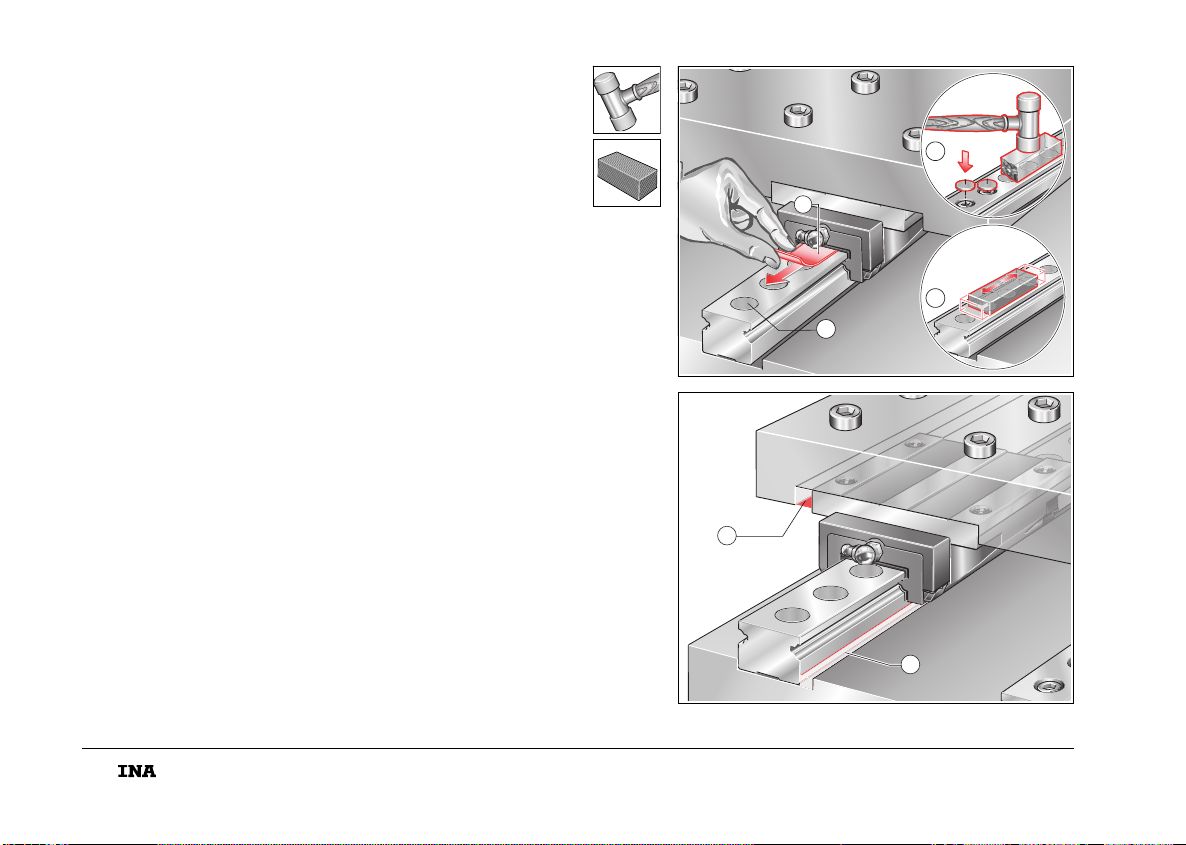
■Verschlusskappen mit Einpressklotz bündig
einpressen.
■Flächen mit Ölstein abziehen.
Corrotect®-beschichtete Führungsschienen und Kunst-
stoff-Verschlusskappen nicht mit Ölstein o.ä. bearbeiten!
DVormontierte Kugelumlaufeinheiten einbauen
■Press the closing plugs in flush using a pressing-in
block .
■Smooth the surfaces using an oilstone .
Do not treat guideways with Corrotect®plating and
plastic closing plugs using an oilstone or similar device.
Fitting of preassembled linear ball bearing and
guideway assembly
1
2
204 019
3
204 020
mon_31_deu_gbr.book Seite 13 Donnerstag, 24. Februar 2005 10:02 10
14
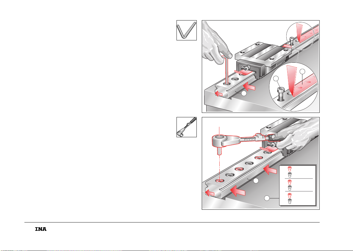
■Umlaufeinheit der Folgeseite auf das Maschinenbett
setzen, Anschlagflächen seitenrichtig zuordnen.
Bei mehrteiligen Schienen Reihenfolge beachten!
Der stirnseitige Spalt muss ⬍0,05 mm sein!
■Dichtlippen mit Federstahlblech schützen.
■Klebeband bohrungsweise abziehen, Schrauben
in die Bohrungen setzen und handfest anziehen.
■Klebeband von den O-Ringen ziehen. Sitz der Ringe
prüfen; Ringe ggf. mit Fett in der richtigen Lage fixieren.
■Führungswagen zu den Bohrungen des Maschinen-
schlittens ausrichten und Schlitten stoßfrei auf die
Wagen setzen.
DVormontierte Kugelumlaufeinheiten einbauen
■Place the recirculating unit for the adjustment side on the
machine bed with the locating surfaces on the correct sides.
If multi-piece guideways are used, note the sequence
of the guideways. The gap at the end face must be smaller
than 0,05 mm.
■Protect the seal lips using a spring steel strip.
■Remove the adhesive strip one hole at a time,
insert the screws in the holes and tighten finger tight.
■Remove the adhesive strip from the O rings . Check the
ring seating and position correctly with grease if necessary.
■Align the carriages with the locating holes in the machine
table and place the table without shock contact on
the carriages .
Fitting of preassembled linear ball bearing and
guideway assembly
3
1
2
204 021
6
6
7
7
204 022
mon_31_deu_gbr.book Seite 14 Donnerstag, 24. Februar 2005 10:02 10
15
■Schrauben in die Bohrungen im Schlitten setzen und
handfest anziehen.
■Wagen gegen die Anschlagflächen des Schlittens
drücken (Pfeil) und Schrauben mit Anziehdreh-
moment MAanziehen.
■Schlitten verfahren und dadurch die Schiene auf der
Folgeseite ausrichten.
■Schrauben in der Führungsschiene nach Anziehschema
anziehen. Anziehdrehmoment MAsiehe Tabelle, Seite 9.
DVormontierte Kugelumlaufeinheiten einbauen
■Insert the fixing screws in the holes in the table and
tighten finger tight.
■Press the carriage against the locating surfaces of the
table (arrow) and tighten the screws to the tightening
torque MA.
■Move the table in order to align the guideway on
the adjustment side.
■Tighten the screws in the guideway in accordance
with the tightening scheme. For the tightening torque MA,
see table, page 9.
Fitting of preassembled linear ball bearing and
guideway assembly
2
1
4
1
5
3
204 023
1. 0,4 M
A
⫻
0,4 M
A
⫻
2. 0,7 M
A
⫻
0,7 M
A
⫻
3. 1,0 M
A
⫻
1,0 M
A
⫻
MA
6
204 024
mon_31_deu_gbr.book Seite 15 Donnerstag, 24. Februar 2005 10:02 10
16
■Verschlusskappen nach Angaben auf Seite 13 montieren.
■Ende an Federstahlblech gerade biegen,
Blech herausziehen.
■Gleichmäßigen Lauf der Umlaufeinheit durch Verfahren
des Schlittens prüfen (Pfeile).
■Wenn notwendig Formschluss der Schiene zu Bett und
Schlitten herstellen, z.B. mit Kunstharz.
DVormontierte Kugelumlaufeinheiten einbauen
■Fit the closing plugs according to the instructions on
page 13.
■Straighten out the ends of the spring steel strip and
remove the strip.
■Check that the recirculating unit runs uniformly by moving
the table (arrows).
■If necessary, fully locate the guideway on the bed and
table , for example by means of synthetic resin.
Fitting of preassembled linear ball bearing and
guideway assembly
1
2
1
1
204 025
3
3
204 026
mon_31_deu_gbr.book Seite 16 Donnerstag, 24. Februar 2005 10:02 10
17
Geschmiert werden kann über Schmiernippel oder eine
Zentralschmieranlage.
Wagen beim Schmieren immer verfahren!
Mindesthub ist viermal Tragkörperlänge!
Vor Inbetriebnahme
■Führungsschienen leicht ölen oder fetten
– abhängig ob Öl- oder Fettschmierung.
■Wagen bei Ölschmierung mit Mindestölmenge schmieren
– Ölmengen Tabelle, Seite 18.
■Bei Fettschmierung Wagen fetten bis frisches Schmierfett
austritt
– Fettmengen Tabelle, Seite 18.
Schmierintervalle
■Schmierfrist beachten
– max. 12 Monate bei Fettschmierung.
■Wird über eine Zentralschmieranlage geschmiert,
Ölimpulsmenge Qimp beachten (Tabelle, Seite 18).
DSchmierung
Lubrication can be carried out via lubrication nipples or a central
lubrication system.
Always move the carriages during lubrication.
The minimum stroke is four times the length of the saddle
plate.
Before initial operation
■Lightly oil or grease the guideways
– depending on whether oil or grease lubrication is used.
■If oil lubrication is used, lubricate the carriages with
the minimum oil quantity
– for oil quantities, see table, page 18.
■If grease lubrication is used, continue greasing the carriage
until fresh grease appears
– for grease quantities, see table, page 18.
Lubrication intervals
■Note the lubrication interval
– max. 12 months if grease lubrication is used.
■If lubrication is carried out by means of a central lubrication
system, note the oil impulse quantity Qimp (table, page 18).
Lubrication
mon_31_deu_gbr.book Seite 17 Donnerstag, 24. Februar 2005 10:02 10
18
DMindestölmenge bei Inbetriebnahme Qmind/
Ölimpulsmenge Qimp
Minimum oil quantity Qmin/
oil impulse quantity Qimp
KUE..(H) Qmind
cm3
Qimp
cm3/h
KUE 15 (H) 0,6 0,3
KUE 20 (H) 0,6 0,3
KUE 25 (H) 0,6 0,3
KUE 30 (H) 0,9 0,5
KUE 35 (H) 1,2 0,6
DErstbefettungsmenge
Initial grease quantity
KUE..(H)
艐g
KUE 15 (H) 1
KUE 20 (H) 1,4
KUE 25 (H) 2
KUE 30 (H) 3
KUE 35 (H) 5
Die Werte gelten für die Bedingungen:
■Einschaltdauer 100%
■C0/P = 8
■=0,8m/s
■Hub 500 mm bis 1000 mm.
Exakte Werte lassen sich nur unter Betriebsbedingungen
ermitteln.
v
The values apply under the following conditions:
■100% operating duration
■C0/P = 8
■=0,8m/s
■stroke 500 mm to 1000 mm.
Precise values can only be determined under operating
conditions.
v
mon_31_deu_gbr.book Seite 18 Donnerstag, 24. Februar 2005 10:02 10

Diese Einbau- und Wartungsanleitung wurde mit großer Sorgfalt
hergestellt.
Alle Angaben sind auf ihre Richtigkeit hin überprüft.
Für etwaige fehlerhafte oder unvollständige Angaben kann jedoch
keine Haftung übernommen werden.
Herausgeber:
INA-Schaeffler KG
Geschäftsbereich Lineartechnik
66406 Homburg (Saar)
Hausadresse:
Berliner Straße 134
66424 Homburg (Saar)
www.ina.com
© by INA · 2005, März
Alle Rechte vorbehalten.
Nachdruck, auch auszugsweise,
ohne unsere Genehmigung nicht gestattet.
Druck: mandelkow gmbh, 91074 Herzogenaurach
Printed in Germany
D
This fitting and maintenance manual has been prepared with
a great deal of care and attention.
All data have been checked for their accuracy.
However, no liability can be accepted for any incorrect or
incomplete data.
Produced by:
INA-Schaeffler KG
Linear Technology Division
66406 Homburg (Saar) · Germany
Mailing address:
Berliner Straße 134
66424 Homburg (Saar) · Germany
www.ina.com
© by INA · March 2005
All rights reserved.
Reproduction in whole or in part,
without our authorization is prohibited.
Printed in Germany by:
mandelkow gmbh, 91074 Herzogenaurach
mon_31_deu_gbr.book Seite 19 Donnerstag, 24. Februar 2005 10:02 10

INA-Schaeffler KG
Geschäftsbereich Lineartechnik
66406 Homburg (Saar)
Internet www.ina.com
E-Mail info.lin[email protected]a.com
In Deutschland:
Telefon 0180/5003872
Fax: 0180 / 5 00 38 73
Aus anderen Ländern:
Telefon +49 / 68 41/ 7 01-0
Fax: +49 / 68 41/ 7 01-6 25
INA Bearing Company Ltd.
Forge Lane, Minworth · Sutton Coldfield
West Midlands · B76 1AP
Telephone: 0121 351 3833
Fax: 0121 351 7686
Website: www.ina.co.uk
Sach-Nr. 018-101-496/MON 31 2-sp. D/GB 030510
mon_31_deu_gbr.book Seite 20 Donnerstag, 24. Februar 2005 10:02 10
Other manuals for KUE Series
1
This manual suits for next models
9
Table of contents
Other INA Industrial Equipment manuals


