manuals.online logo
Brands
  1. Home
  2. •
  3. Brands
  4. •
  5. Allen-Bradley
  6. •
  7. Power Supply
  8. •
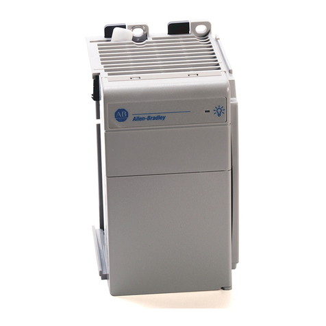
  9. Allen-Bradley 1771-P4S User manual

Allen-Bradley 1771-P4S User manual

(217) 352-9330 | [email protected] | artisantg.com
-~
ARTISAN
®
~I
TECHNOLOGY
GROUP
Your definitive source
for
quality
pre-owned
equipment.
Artisan Technology
Group
Full-service,
independent
repair
center
with
experienced
engineers
and
technicians
on staff.
We
buy
your
excess,
underutilized,
and
idle
equipment
along
with
credit
for
buybacks
and
trade-ins
.
Custom
engineering
so
your
equipment
works
exactly as
you
specify.
•
Critical
and
expedited
services
•
Leasing
/
Rentals/
Demos
• In
stock/
Ready-to-ship
•
!TAR-certified
secure
asset
solutions
Expert
team
ITrust
guarantee
I
100%
satisfaction
All
tr
ademarks,
br
a
nd
names, a
nd
br
a
nd
s a
pp
earing here
in
are
th
e property of
th
e
ir
r
es
pecti
ve
ow
ner
s.
Find the Rockwell / Allen-Bradley 1771-P4S at our website: Click HERE
Power Supply Modules
(Cat. No. 1771-P4S, -P6S, -P6S1, -P6S1)
Installation Data
1
AllenBradley
Power Supply Modules
(cat. no. 1771-P4S, -P6S, -P4S1, -P6S1)
This document provides you with the following information:
what this package contains
tasks on installing your power supply module
interpreting the power supply indicators
troubleshooting your power supply
When you receive your power supply, you should see the following
components in the box:
one 1771-P4S, -P6S, -P4S1, or -P6S1 power supply module
one 5-position terminal block (attached to module)
To install your power supply, you need to know how to perform the
following tasks:
set the jumpers
place the power supply in a chassis
connect a paralleling cable (if using a second supply)
connect input power
Set the Jumpers
Each power supply module has two jumpers located at the back edge of the
module near the gold-plated edge connectors. The jumper selection
provides the proper voltage regulation for the different power supply
configurations. The power supply can be configured to support local or
remote sensing by setting the jumpers.
To
the Installer
What This Power Supply
Package Contains
Installing the Power Supply
Module
Artisan Scientific - Quality Instrumentation ... Guaranteed | (888) 88-SOURCE | www.artisan-scientific.com
Power Supply Modules
(Cat. No. 1771-P4S, -P6S, -P6S1)
Installation Data
2
To configure the supply:
1. Position the power supply module so that the jumpers and pins are
facing upward as shown in figure 1.
Figure 1
Power Supply Jumpers
2. Set the jumpers as shown in table A. Use needle nose pliers to set the
jumpers.
Table A
Jumper Settings
For This Configuration Set Jumpers to:
A single power supply in a powersupply chassis
connected to an I/O chassis through a power cable.
right position
All other configurations. (Power supplies are
shipped with jumpers in this position.)
left position
Place the Power Supply in a Chassis
WARNING: Turn off all power-supply modules before
removing modules from or inserting modules into a chassis.
Failure to observe this warning could alter processor memory,
damage module circuitry, and cause unintended operation which
could possibly cause injury to personnel.
Artisan Scientific - Quality Instrumentation ... Guaranteed | (888) 88-SOURCE | www.artisan-scientific.com
Power Supply Modules
(Cat. No. 1771-P4S, -P6S, -P6S1, -P6S1)
Installation Data
3
You can place these power-supply modules into any I/O module slot in any
current chassis (1771-A1B, -A2B, -A3B, -A4B, -A3B1, -PSC).
However, to place these power-supply modules into a superseded I/O
chassis (1771-A1, -A2, -A4), you must follow the restrictions in table B.
Table B
Placement Restrictions in Superseded I/O Chassis (1771A1, A2, A4)
Adapter or
Inchassis
processor
I/O
Chassis
1st
Power Supply12nd
Power Supply1
Without A4 I/Oslot 0 I/Oslot 10
an integral
power supply
A2 I/Oslot 0 I/Oslot 4
power supply A1 I/Oslot 0 not applicable
With an integral A4 not applicable I/Oslot 8
g
power supply A2 not applicable I/Oslot 3
1I/O
module slots are numbered 0 through 15, left to right.
Connect a Paralleling Cable
You can use two power supplies in the same I/O chassis to produce more
power by connecting them with a Power-Supply Paralleling Cable
(1771-CT). This connection is for communication between the two
supplies. If one supply has to shut down, it tells the second to turn off its
indicator. Although the adapter or in-chassis processor will be disabled, the
second supply will continue trying to operate until its DC output limits are
exceeded. Because the adapter or in-chassis processor is disabled,
paralleling two supplies does not provide redundancy.
To connect the paralleling cable:
1. Connect the paralleling cable between the P/S PARALLEL
connectors on the two supplies (figure 2).
2. Loop the paralleling cable over the top of the I/O chassis to avoid
picking up signals induced from I/O wiring.
3. Turn on the supplies simultaneously. If you don’t, the first supply you
turn on may shut down due to an overcurrent condition.
Artisan Scientific - Quality Instrumentation ... Guaranteed | (888) 88-SOURCE | www.artisan-scientific.com
Power Supply Modules
(Cat. No. 1771-P4S, -P6S, -P6S1)
Installation Data
4
Figure 2
Paralleling Cable and AC Power Connections
Connect Input Power
Figure 2 shows the overall configuration of the ac power connections.
To make ac power connections:
1. Connect the high side of the power source to the L1 terminal of the
power supply.
2. Connect the low side of the power source to the L2 or N (neutral)
terminal of the power supply.
3. Connect the GND (ground) terminal of the power supply to the
central ground bus in the enclosure.
Artisan Scientific - Quality Instrumentation ... Guaranteed | (888) 88-SOURCE | www.artisan-scientific.com
Power Supply Modules
(Cat. No. 1771-P4S, -P6S, -P6S1, -P6S1)
Installation Data
5
Figure 3 shows details of how to connect a wire to a terminal on the
terminal block. You can connect these wires while the terminal block is
plugged into the supply, or you can remove the block to lay it on a flat
surface to connect these wires. To remove the block, pull it straight out out
from the receptacle on the module.
The 2 undesignated terminals do not connect to any electrical circuit on the
module and are not used. Each of the three functional terminals accepts a
single 14-AWG wire max.
To connect a wire to a terminal:
1. Strip 0.35 inches of insulation off the wire.
2. Spring the clip open to insert the wire, using a wedge-tipped tool such
as a small screwdriver. If you leave the terminal block plugged into
the supply, insert the tool parallel to the wire (push straight in). If you
remove the terminal block and lay it on a flat surface, insert the tool
perpendicular to the wire (push straight down).
3. After making the wiring connections, re-insert the terminal block into
the front plate. Be sure that the plug is completely inserted and that
the locking prongs are engaged.
Figure 3
Connecting a W
ire to a Terminal
Your power supply has an indicator located in the upper half of the module
front panel labeled P/S ACTIVE. Table C shows how to interpret the P/S
ACTIVE indicator.
Interpreting the Power Supply
Indicators
Artisan Scientific - Quality Instrumentation ... Guaranteed | (888) 88-SOURCE | www.artisan-scientific.com
Power Supply Modules
(Cat. No. 1771-P4S, -P6S, -P6S1)
Installation Data
6
Table C
Interpreting the P/S ACTIVE Indicator
If the indicator
Is:
Then:
On The power supply (and any supply connected through a paralleling cable) is
operating normally. However, it could still have a poor connection to the
backplane.
Off The supply has detected one of the following conditions:
Gdc overvoltage (the supply shuts down)
Gdc undervoltage (the supply shuts down)
Gdc overcurrent (the supply shuts down)
Gpower switch turned off (the supply is turned off)
Gac undervoltage
Gthe paralleled supply is shut down
With ac undervoltage or a paralleled supply shut down, the supply will still
attempt to generate the output. When dc limits are exceeded, the supply shuts
down until you turn power off (for 5 seconds minimum) and then back on.
If you have a single power supply installed in an I/O chassis and its P/S
ACTIVE indicator is off, verify the ground connection to the supply; then
follow this troubleshooting flow chart.
Troubleshooting a Single
Power Supply
Artisan Scientific - Quality Instrumentation ... Guaranteed | (888) 88-SOURCE | www.artisan-scientific.com
Power Supply Modules
(Cat. No. 1771-P4S, -P6S, -P6S1, -P6S1)
Installation Data
7
If you have a pair of power supplies installed in parallel in an I/O chassis
and the P/S ACTIVE indicators are off, verify the ground connection to
each supply; then follow this troubleshooting flow chart.
Troubleshooting
Parallel
Power Supplies
Artisan Scientific - Quality Instrumentation ... Guaranteed | (888) 88-SOURCE | www.artisan-scientific.com
Power Supply Modules
(Cat. No. 1771-P4S, -P6S, -P6S1)
Installation Data
8
Specifications
1771P4S 1771P6S 1771P4S1 1771P6S1
Input Voltage 120V ac 220V ac 100V ac 200V ac
Input Range 97 132V ac rms 194 - 264V ac rms 85 - 120V ac rms 170 - 240V ac rms
Frequency 47 - 63 Hz 47 - 63 Hz 47 - 63 Hz 47 - 63 Hz
Fuse 1.5A 250V Slowblow
Output Voltage (Backplane) 5V dc
Output Current (max) 8A
Wire Size 14 AWG max (single wire only)
Environmental Conditions Operational Temperature: 0 to 60°C (32 to 140 °F)
Storage Temperature: 40 to 85°C (40 to 185 °F)
Relative Humidity: 5 to 95% (without condensation)
Physical Width 1 I/O chassis slot
Weight 1.85 lbs (0.84 kg)
5position Terminal Block AB P/N 94127405, Wago 1 P/N 231205/000008 (1 included with each power supply)
1Wago
Corporation 9085 N. Deerbrook T
rail, Brown Deer WI 53223
With offices in major cities worldwide
WORLD
HEADQUARTERS
Allen-Bradley
1201 South Second Street
Milwaukee, WI 53204 USA
Tel: (1) 414 382-2000
Telex: 43 11 016
FAX: (1) 414 382-4444
EUROPE/MIDDLE
EAST/AFRICA
HEADQUARTERS
Allen-Bradley Europe B.V.
Amsterdamseweg 15
1422 AC Uithoorn
The Netherlands
Tel: (31) 2975/43500
Telex: (844) 18042
FAX: (31) 2975/60222
ASIA/PACIFIC
HEADQUARTERS
Allen-Bradley (Hong Kong)
Limited
Room 1006, Block B, Sea
View Estate
28 Watson Road
Hong Kong
Tel: (852) 887-4788
Telex: (780) 64347
FAX: (852) 510-9436
CANADA
HEADQUARTERS
Allen-Bradley Canada
Limited
135 Dundas Street
Cambridge, Ontario N1R
5X1
Canada
Tel: (1) 519 623-1810
FAX: (1) 519 623-8930
LATIN AMERICA
HEADQUARTERS
Allen-Bradley
1201 South Second Street
Milwaukee, WI 53204 USA
Tel: (1) 414 382-2000
Telex: 43 11 016
FAX: (1) 414 382-2400
As a subsidiary of Rockwell International, one of the world’s largest technology
companies — Allen-Bradley meets today’s challenges of industrial automation with over
85 years of practical plant-floor experience. More than 11,000 employees throughout the
world design, manufacture and apply a wide range of control and automation products
and supporting services to help our customers continuously improve quality, productivity
and time to market. These products and services not only control individual machines but
integrate the manufacturing process, while providing access to vital plant floor data that
can be used to support decision-making throughout the enterprise.
Publication 1771–2.135–February 1990
Supersedes Publication 1771–2.135–Febuary 1989 PN 955106–86
Copyright 1992 Allen-Bradley Company, Inc. Printed in USA
Artisan Scientific - Quality Instrumentation ... Guaranteed | (888) 88-SOURCE | www.artisan-scientific.com
Artisan
Technology
Group
is
an independent supplier
of
quality pre-owned equipment
Gold-standard
solutions
Extend the life
of
your
critical industrial,
commercial, and military systems
with
our
superior service and support.
We
buy
equipment
Planning to
upgrade
your current
equipment? Have surplus equipment taking
up shelf space? We'll give it a
new
home.
Learn
more!
Visit us at artisantg.com for more info
on price quotes, drivers, technical
specifications, manuals, and documentation.
Artisan Scientific
Corporation
dba
Artisan
Technology
Group
is
not
an affiliate,
representative,
or
authorized
distributor
for
any
manufacturer
listed herein.
We're here to make your life easier.
How
can
we
help you today?
(217)
352-9330
Isales@artisantg.com Iartisantg.com

This manual suits for next models

3

Other Allen-Bradley Power Supply manuals

Allen-Bradley ControlLogix 1756-PA75R/A User manual

Allen-Bradley

Allen-Bradley ControlLogix 1756-PA75R/A User manual

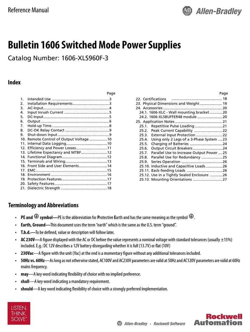
Allen-Bradley 1606-XLS960F-3 User manual

Allen-Bradley

Allen-Bradley 1606-XLS960F-3 User manual

Allen-Bradley 1606-XLB User manual

Allen-Bradley

Allen-Bradley 1606-XLB User manual
Allen-Bradley FLEX Ex 1797-PS2E2 User manual

Allen-Bradley

Allen-Bradley FLEX Ex 1797-PS2E2 User manual

Allen-Bradley Kinetix 5700 User manual

Allen-Bradley

Allen-Bradley Kinetix 5700 User manual

Allen-Bradley 1771-P4R Installation and user guide

Allen-Bradley

Allen-Bradley 1771-P4R Installation and user guide

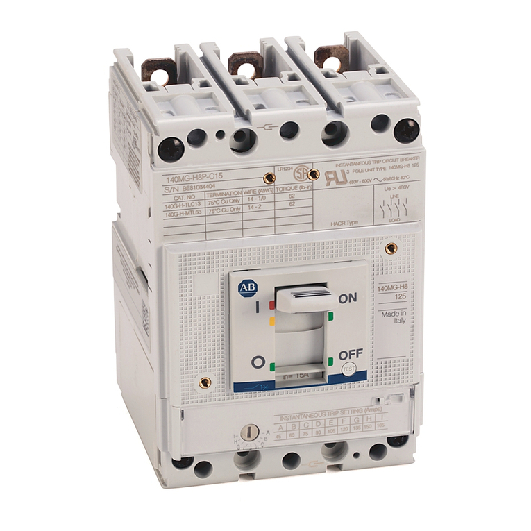
Allen-Bradley 140G Series User manual

Allen-Bradley

Allen-Bradley 140G Series User manual

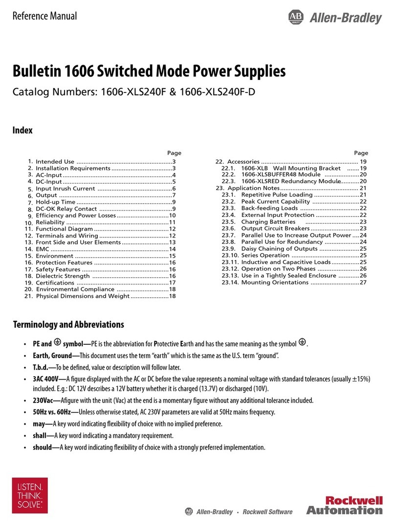
Allen-Bradley 1606-XLS240F User manual

Allen-Bradley

Allen-Bradley 1606-XLS240F User manual

Allen-Bradley Series B User manual

Allen-Bradley

Allen-Bradley Series B User manual

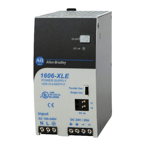
Allen-Bradley 1606-XLE480FP-D User manual

Allen-Bradley

Allen-Bradley 1606-XLE480FP-D User manual

Allen-Bradley FLEX Ex 1797-PS1E User manual

Allen-Bradley

Allen-Bradley FLEX Ex 1797-PS1E User manual

Allen-Bradley 1771-P7 Series C User manual
Allen-Bradley

Allen-Bradley 1771-P7 Series C User manual

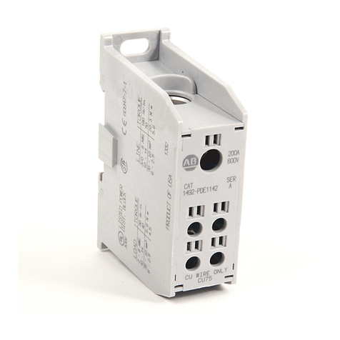
Allen-Bradley 1492-PDE1112 Service manual

Allen-Bradley

Allen-Bradley 1492-PDE1112 Service manual

Allen-Bradley 1794-PS3 User manual

Allen-Bradley

Allen-Bradley 1794-PS3 User manual

Allen-Bradley 1606-XLS960E-3 User manual

Allen-Bradley

Allen-Bradley 1606-XLS960E-3 User manual

Allen-Bradley 1606-BATASSY2 User manual

Allen-Bradley

Allen-Bradley 1606-BATASSY2 User manual

Allen-Bradley Kinetix 5700 iTRAK User manual

Allen-Bradley

Allen-Bradley Kinetix 5700 iTRAK User manual

Allen-Bradley ControlLogix 1756-PA50K User manual

Allen-Bradley

Allen-Bradley ControlLogix 1756-PA50K User manual

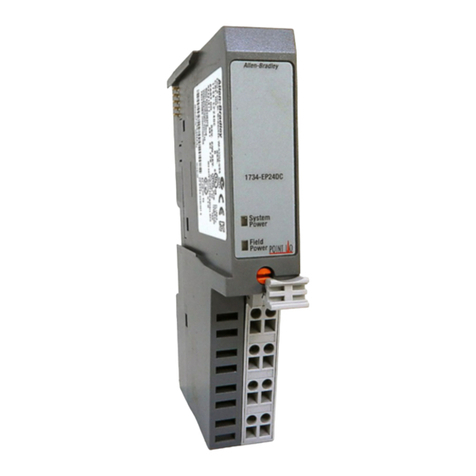
Allen-Bradley 1734-EP24DC User manual

Allen-Bradley

Allen-Bradley 1734-EP24DC User manual

Allen-Bradley 1606-XLERED20Y User manual

Allen-Bradley

Allen-Bradley 1606-XLERED20Y User manual

Allen-Bradley 1606-XLB36EH User manual

Allen-Bradley

Allen-Bradley 1606-XLB36EH User manual

Allen-Bradley 1734-EP24DC User manual

Allen-Bradley

Allen-Bradley 1734-EP24DC User manual

Allen-Bradley 1606-XLB480E User manual

Allen-Bradley

Allen-Bradley 1606-XLB480E User manual

Allen-Bradley 1606-XLE480FP User manual

Allen-Bradley

Allen-Bradley 1606-XLE480FP User manual

Popular Power Supply manuals by other brands

VOSS.farming Sunny 200 instruction manual

VOSS.farming

VOSS.farming Sunny 200 instruction manual

mini-box M4-ATX-HV installation guide

mini-box

mini-box M4-ATX-HV installation guide

Altronix eFlow104NBV installation guide

Altronix

Altronix eFlow104NBV installation guide

Elettrotest CPS/T Series user manual

Elettrotest

Elettrotest CPS/T Series user manual

Pulsar HPSBH-12V3A-B user manual

Pulsar

Pulsar HPSBH-12V3A-B user manual

TDK-Lambda Genesys GENH Series user manual

TDK-Lambda

TDK-Lambda Genesys GENH Series user manual

Good Will Instrument GPS-S Series user manual

Good Will Instrument

Good Will Instrument GPS-S Series user manual

Iniven IP-40 instruction manual

Iniven

Iniven IP-40 instruction manual

Western Co WRM15 dualB Technical manual

Western Co

Western Co WRM15 dualB Technical manual

Altronix Trove T1MK1F4 installation guide

Altronix

Altronix Trove T1MK1F4 installation guide

B.E.G. LUXOMAT PS-DALISYS-USB-REG Mounting instructions

B.E.G.

B.E.G. LUXOMAT PS-DALISYS-USB-REG Mounting instructions

Thermaltake SMART 700W manual

Thermaltake

Thermaltake SMART 700W manual

VTOMAN Jump 600 user manual

VTOMAN

VTOMAN Jump 600 user manual

Rohde & Schwarz NGA100 user manual

Rohde & Schwarz

Rohde & Schwarz NGA100 user manual

ZALMAN ZM450-GS user manual

ZALMAN

ZALMAN ZM450-GS user manual

Matsusada R4G Series instruction manual

Matsusada

Matsusada R4G Series instruction manual

Xantrex XPF 35-10 operating manual

Xantrex

Xantrex XPF 35-10 operating manual

Bay Networks HRPSU Installation and Maintenance

Bay Networks

Bay Networks HRPSU Installation and Maintenance

manuals.online logo
manuals.online logoBrands
  • About & Mission
  • Contact us
  • Privacy Policy
  • Terms and Conditions

Copyright 2025 Manuals.Online. All Rights Reserved.