manuals.online logo
Brands
  1. Home
  2. •
  3. Brands
  4. •
  5. Allen-Bradley
  6. •
  7. Power Supply
  8. •
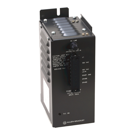
  9. Allen-Bradley 1771-P2 User manual

Allen-Bradley 1771-P2 User manual

9pin plugs
1771CE or CD cable
19568
Labels on each plug
identify proper connection.
Auxiliary Power Supply
(Cat. No. 1771-P2)
Installation Data
This document provides information on:
preparing to install the power supply
installing the power supply
connecting ac power to the power supply
power supply output
troubleshooting
specifications
The auxiliary power supply can power one bulletin 1771 I/O chassis
when used with an adapter module, a 1772 Mini-PLC-2processor, or a
1772 Mini-PLC-2/15processor.
The auxiliary power supply does not provide battery backup. For battery
backup, use a system power supply (cat. no. 1771-P1).
If You Are Mounting the Power Supply: Use this Power Cable (Cat. No.):
on the left side of the chassis 1771CE
within 5 cablefeet of the I/O chassis 1771CD
If you mount the power supply on the left side-plate of the I/O chassis,
mount the I/O chassis first (if you have not already done so). See the
Universal I/O Chassis Installation Data (publication 1771-2.210) for
information on mounting the I/O chassis.
When mounted separately, the power supply can be mounted above or next
to the I/O chassis. It can not be mounted below since it is necessary to
allow convection cooling of both the power supply and the I/O chassis.
A minimum vertical distance of six inches should be maintained.
To the Installer
Prepare for Installation
Install the Power Supply and
Connect Backplane Power
Installation Data
Auxiliary Power Supply
Cat. No. 1771P2
2
Mount the Power Supply
ATTENTION: If you do not remove system power, you could
damage the module circuitry and/or cause undesired operation
with possible injury to personnel.
1. Remove system power.
2. Mount the power supply.
If Mounting Separately: If Mounting on Left Side of Chassis:
use the rear flanges
to mount it to a panel.
Mount the power supply up to 5 cablefeet
from the I/O chassis.
11.25"
(285mm)
263mm
(10.37")
Depth is 182mm (7.16")
116mm
(4.56")
45mm
(1.8")
12593-I
Important: Do not mount the power supply below
the I/O chassis.
19569
Use the four screws supplied with the I/O chassis
to install the power supply onto the I/O chassis.
flat washer
screw
Important: Place the flat washers provided between each mounting
screw and the power supply. If you do not use the flat washers, the
mounting screw intrudes into the I/O chassis and interferes with
module insertion.
L1
120V ac
L2
EQUIP
. GND
SPARE
220/240V ac
120V ac
SPARE
120V
Operation
11939
L1
L2
EQUIP.
GND
SPARE
220/240V ac
120V ac
SPARE
220/240V
Operation
metal jumper
metal jumper
120V ac
ac line
120 V ac 1A SB
220/240 V ac 0.5A SB
Installation Data
Auxiliary Power Supply
Cat. No. 1771P2
4
Before connecting ac power to the power supply, you must:
check the input voltage
check the fuse protection
Check the Input Voltage
The power supply is factory-shipped for 120V ac operation. You can use:
120V ac
or
220/240V ac
Two metal jumpers are installed on the front terminal strip at the positions
indicating 120V ac.
ATTENTION: Be sure the power supply is correctly jumpered
for either 120V ac or 220/240V ac. Incorrect jumpering on the
terminal strip may cause improper operation or damage to the
power supply.
If you are using the power supply for 220/240V ac operation, remove both
metal jumpers on the terminal strip from their original 120V positions.
Install one of these jumpers at the terminal labeled 220/240V ac.
Check the Fuse Protection
The power supply is protected from overcurrent at its inputs by a
slow-blow fuse. The power supply comes with one 1A slow-blow fuse
installed for 120V operation. If you are using the power supply for
220/240V operation, remove the 1A fuse and replace it with the 0.5A
slow-blow fuse that is provided. Replacement fuses are shown below:
Input Voltage Fuse Manufacturer's No.
120V ac 3AG
1A
Bussman: MDL 1A
Littelfuse: 313001
220/240V ac 3AG
0.5A
Bussman: MDL 0.5A
Littelfuse: 313.500
A replacement fuse kit (cat. no. 1771-FP) containing both 1A and 0.5A
fuses is available. Contact your local Allen-Bradley representative for
further information.
Connect AC Power
Installation Data
Auxiliary Power Supply
Cat. No. 1771P2
7
Nominal Input Voltage/Current 120V ac @ .75A
220/240V ac @ .38A
Input for 120V operation
Voltage Range for 220/240V operation
98132V ac
196250V ac
Input Power real
apparent
65W @ full load
90VA @ full load
External Transformer (if used) 160VA @ full load
Frequency Range 60/50Hz
Isolation Voltage 2500V dc for 1s
1800V rms for 1s input power to equipment/chassis ground
Output logic circuitry
Voltage memory
5.1V dc ±5%
5.1V dc ±5%
Output Current 6.5A maximum @ 5V dc
Power Loss Time Delay 
Input Power Loss to Processor Disable
13.5ms ±2.5ms
Replacement for 120V operation
Fuses for 220/240V operation
1A, 3AG (slow blow); Bussmann MDL 1  Littelfuse 313001
0.5A, 3AG (slow blow); Bussmann MDL 0.5  Littelfuse 313.500
Weight 5.89 kg (13 lbs)
Dimensions (W x H x D) 11.6cm x 28.6cm x 18.2cm
(4.56" x 11.25" x 7.16")
Environmental Operating Temperature
Conditions: Storage Temperature
Relative Humidity
0 to 60°C (32 to 140°F)
40 to 85°C (40 to 185°F)
5 to 95%, noncondensing
Location left side of 1771 I/O chassis or 5 cablefeet from I/O chassis
Cables 1771CD
1771CE
1.52m (5 ft)  connects I/O chassis to panel mounted 1771P2
.30m (1 ft) - connects I/O chassis to chassis mounted 1771P2
Use these graphs to determine your:
cooling requirements
power cost
transformer size (unless the transformer manufacturer has a
recommended multiplier for sizing a transformer for an ac-to-dc power
supply)
0
2
4
6
8
0 25 50 75 100
0
2
4
6
8
0 20 40 60 80
Apparent Power (VA) Real Power (Watts)
Backplane
Load Current
(Amps)
0
2
4
6
8
0 50 100 150 200
Transformer Sizing (VA) =
Real Power (Watts) x 2.5
PLC-2 and PLC-2/15 are registered trademarks of Allen-Bradley Company, Inc.
Specifications

Other Allen-Bradley Power Supply manuals
Allen-Bradley 1756-PA75R Service manual

Allen-Bradley

Allen-Bradley 1756-PA75R Service manual

Allen-Bradley 1606-XLE480EM User manual

Allen-Bradley

Allen-Bradley 1606-XLE480EM User manual

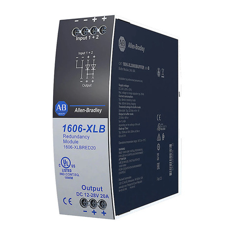
Allen-Bradley 1606-XLB User manual

Allen-Bradley

Allen-Bradley 1606-XLB User manual

Allen-Bradley 1771-P2 Installation and user guide

Allen-Bradley

Allen-Bradley 1771-P2 Installation and user guide

Allen-Bradley ControlLogix 1756-PA75R/A User manual

Allen-Bradley

Allen-Bradley ControlLogix 1756-PA75R/A User manual

Allen-Bradley Bulletin 1606 User manual

Allen-Bradley

Allen-Bradley Bulletin 1606 User manual

Allen-Bradley Rockwell Automation 1606-XLP60EQT User manual

Allen-Bradley

Allen-Bradley Rockwell Automation 1606-XLP60EQT User manual

Allen-Bradley 1756-PA30XT User manual

Allen-Bradley

Allen-Bradley 1756-PA30XT User manual

Allen-Bradley 1606-XLE480FP User manual

Allen-Bradley

Allen-Bradley 1606-XLE480FP User manual

Allen-Bradley 1492-PDE1112 Service manual

Allen-Bradley

Allen-Bradley 1492-PDE1112 Service manual

Allen-Bradley 1609-HDK1 User manual

Allen-Bradley

Allen-Bradley 1609-HDK1 User manual

Allen-Bradley Kinetix 5700 iTRAK User manual

Allen-Bradley

Allen-Bradley Kinetix 5700 iTRAK User manual

Allen-Bradley ControlLogix 1756-PA75/B User manual

Allen-Bradley

Allen-Bradley ControlLogix 1756-PA75/B User manual

Allen-Bradley Bulletin 1609 User manual

Allen-Bradley

Allen-Bradley Bulletin 1609 User manual

Allen-Bradley 1606-XLE480FP-D User manual

Allen-Bradley

Allen-Bradley 1606-XLE480FP-D User manual

Allen-Bradley FLEX Ex 1797-PS1E User manual

Allen-Bradley

Allen-Bradley FLEX Ex 1797-PS1E User manual

Allen-Bradley 1771-P4S User manual

Allen-Bradley

Allen-Bradley 1771-P4S User manual

Allen-Bradley 140G-N User manual

Allen-Bradley

Allen-Bradley 140G-N User manual

Allen-Bradley 1606-XLB60E User manual

Allen-Bradley

Allen-Bradley 1606-XLB60E User manual

Allen-Bradley FLEX Ex 1797-PS2E2 User manual

Allen-Bradley

Allen-Bradley FLEX Ex 1797-PS2E2 User manual

Allen-Bradley 8720MC-RPS065 User manual

Allen-Bradley

Allen-Bradley 8720MC-RPS065 User manual

Allen-Bradley Series B User manual

Allen-Bradley

Allen-Bradley Series B User manual

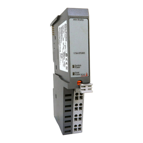
Allen-Bradley 1734-EP24DC User manual

Allen-Bradley

Allen-Bradley 1734-EP24DC User manual

Allen-Bradley 1606-XLS240E User manual
Allen-Bradley

Allen-Bradley 1606-XLS240E User manual

Popular Power Supply manuals by other brands

Aervoe Sierra Wave EnerPlex 9700 operating instructions

Aervoe

Aervoe Sierra Wave EnerPlex 9700 operating instructions

Vox Power NEVO+600 Series user manual

Vox Power

Vox Power NEVO+600 Series user manual

M-system M5DYH2 instruction manual

M-system

M-system M5DYH2 instruction manual

HP E3610A operating manual

HP

HP E3610A operating manual

Monacor PSS-3800SV operating instructions

Monacor

Monacor PSS-3800SV operating instructions

Extron electronics PS 1230 installation guide

Extron electronics

Extron electronics PS 1230 installation guide

Extron electronics VNM 12 PS installation guide

Extron electronics

Extron electronics VNM 12 PS installation guide

Eurotherm TC3001 user manual

Eurotherm

Eurotherm TC3001 user manual

Puls DIMENSION CP10.122 installation manual

Puls

Puls DIMENSION CP10.122 installation manual

Gallagher S20 instructions

Gallagher

Gallagher S20 instructions

Akyga AK-TB-13 user manual

Akyga

Akyga AK-TB-13 user manual

Altronix LPS3AC installation guide

Altronix

Altronix LPS3AC installation guide

Rohde & Schwarz TS-PSU12 user manual

Rohde & Schwarz

Rohde & Schwarz TS-PSU12 user manual

Puls FPS300.245-049-112 installation manual

Puls

Puls FPS300.245-049-112 installation manual

Tescom 650 user manual

Tescom

Tescom 650 user manual

Puls PIANO Series manual

Puls

Puls PIANO Series manual

alfatronix AD Series Operating & assembly instructions

alfatronix

alfatronix AD Series Operating & assembly instructions

BEHLMAN PF1352 Series manual

BEHLMAN

BEHLMAN PF1352 Series manual

manuals.online logo
manuals.online logoBrands
  • About & Mission
  • Contact us
  • Privacy Policy
  • Terms and Conditions

Copyright 2025 Manuals.Online. All Rights Reserved.