Inciner8 i8-75a User manual

Leading Provider of Thermal Treatment Solutions
+44 (0) 1704 884020
i8-75a Incinerator
Installation & Operation Manual

Parameter
Inciner8 Limited. Company Registered in England & Wales - REG: 04866401
VAT Registration: 855999544
Enter the world of:
www.inciner8.com
+44 (0) 1704 884020
Leading Provider of Thermal Treatment Solutions
General Responsibility
PLEASE READ THIS INFORMATION:
We don’t accept responsibility for any damages or injuries caused by neglecting these instructions.
Purchased equipment is in compliance with existing regulations for safety measures .Treatment and
Handling of equipment is end-user’s responsibility.
Our incinerators are made from existing technology and regulations of safety measures.
Nevertheless, because of improper usage and handling some serious injures for user or other
person, as well as physical damage to equipment or other goods may occur.
These incinerators are intended for incineration of waste products and for energy recycling from
exhaust heat. (This is optional equipment). Any usage of incinerator beside mentioned is considered
as improper, and end-user takes full responsibility for possible damages and injuries.
Proper usage of incinerator also considers installation, maintenance and service of equipment as
described in this manual.
Installation and calibration of incinerator, as well as service and maintenance procedures can be
done only by approved professionals.

Parameter
Inciner8 Limited. Company Registered in England & Wales - REG: 04866401
VAT Registration: 855999544
Enter the world of:
www.inciner8.com
+44 (0) 1704 884020
Leading Provider of Thermal Treatment Solutions
Read and Understand this Manual
WARRANTY
INCINER8's exclusive warranty is that the products are free from defects in materials and
workmanship for a period of one year (or other period if specied) from date of sale by INCINER8.
INCINER8 MAKES NO WARRANTY OR REPRESENTATION, EXPRESS OR IMPLIED, REGARDING
NON-INFRINGEMENT, MERCHANTABILITY, OR FITNESS FOR PARTICULAR PURPOSE OF THE
PRODUCTS. ANY BUYER OR USER ACKNOWLEDGES THAT THE BUYER OR USER ALONE HAS
DETERMINED THAT THE PRODUCTS WILL SUITABLY MEET THE REQUIREMENTS OF THEIR
INTENDED USE. INCINER8 DISCLAIMS ALL OTHER WARRANTIES, EXPRESS OR IMPLIED.
LIMITATIONS OF LIABILITY
INCINER8 SHALL NOT BE RESPONSIBLE FOR SPECIAL, INDIRECT, OR CONSEQUENTIAL
DAMAGES, LOSS OF PROFITS OR COMMERCIAL LOSS IN ANY WAY CONNECTED WITH THE
PRODUCTS, WHETHER SUCH CLAIM IS BASED ON CONTRACT, WARRANTY, NEGLIGENCE, OR
STRICT LIABILITY.
In no event shall the responsibility of INCINER8 for any act exceed the individual price of the
product on which liability is asserted.
IN NO EVENT SHALL INCINER8 BE RESPONSIBLE FOR WARRANTY, REPAIR, OR OTHER CLAIMS
REGARDING THE PRODUCTS UNLESS INCINER8’S ANALYSIS CONFIRMS THAT THE PRODUCTS
WERE PROPERLY HANDLED, STORED, INSTALLED, AND MAINTAINED AND NOT SUBJECT TO
CONTAMINATION, ABUSE, MISUSE, OR INAPPROPRIATE MODIFICATION OR REPAIR

Parameter
Inciner8 Limited. Company Registered in England & Wales - REG: 04866401
VAT Registration: 855999544
Enter the world of:
www.inciner8.com
+44 (0) 1704 884020
Leading Provider of Thermal Treatment Solutions
Safety
PLEASE ADHERE TO THESE GUIDELINES
Use appropriate lifting equipment when installing incinerator. Failure to do so may cause injury or damage the machinery
Use appropriately qualied personnel for the fuel and electrical connections.
Ensure the incinerator is cured prior to rst use. Failure to do so will void the warranty.
Do not modify the incinerator or any of its parts in any way. Doing so will void the warranty.
Wear suitable Personal Protection Equipment (PPE) when operating the incinerator to prevent injury during loading of
waste into chamber. Please check the PPE requisites for your country.
Ensure ash has cooled down before removal to avoid injury.
Do not overll the incinerator.
Ensure the loading door is closed and locked during operation to prevent un-authorised entry to the chamber whilst burn
cycle is in process.
In case of loss of electricity, shut down the burner immediately to prevent damage to the burner by heat transferring back
for the main chamber.
Ensure installation and layout is compliant with local building regulations.
Regularly check the condition of your incinerator to ensure it is in good condition. Service every 1 year/1000 hours
(whichever comes rst).
Do not use cleaning agents containing chlorine, acid or other aggressive materials on your incinerator. This can remove
the paint and lead to corrosion.
If any signs of corrosion do appear, treat immediately with high temperature paint to prevent the corrosion spreading.
Ensure the incinerator has constant electrical supply when in use. If power supply is susceptible to failures, consider the
use of a generator.
If power does fail during the burn cycle, remove burners immediately to prevent damage to them.
Ensure the incinerator is used in the manner for which it was intended – waste incineration (including following this
instruction manual). Using this product in any other way is considered improper, and the end user accepts full responsi-
bility for any possible injuries/damage.
Ensure explosive/ammable materials are not stored in close proximity to the incinerator.

Parameter
Inciner8 Limited. Company Registered in England & Wales - REG: 04866401
VAT Registration: 855999544
Enter the world of:
www.inciner8.com
+44 (0) 1704 884020
Leading Provider of Thermal Treatment Solutions
Preface
Thank you for purchasing an i8-75a incinerator.
This manual describes how to use the i8-75a. Read this manual thoroughly and be sure you understand it before
attempting to use the Incinerator and use the incinerator correctly according to the information provided. Keep this
manual in a safe place for easy reference.
©INCINER8, 2015
All rights reserved. No part of this publication may be reproduced, stored in a retrieval system or transmitted, in any
form, or by any means, mechanical, electronic, photocopying, recording, or otherwise, without the prior written
permission of INCINER8.
No patent liability is assumed with respect to the use of the information contained herein. Moreover, because
INCINER8 is constantly striving to improve its high-quality products, the information contained in this manual is
subject to change without notice. Every precaution has been taken in the preparation of this manual. Nevertheless,
INCINER8 assumes no responsibility for errors or omissions. Neither is any liability assumed for damages resulting
from the use of the information contained in this publication.

Inciner8 Limited. Company Registered in England & Wales - REG: 04866401
VAT Registration: 855999544
Enter the world of:
www.inciner8.com
+44 (0) 1704 884020
Leading Provider of Thermal Treatment Solutions
Package Contents
MODEL: i8-75A
Please remember
We take great care in ensuring all parts are included ifor the assembly of your product. Please check the package
contents against the list above and contact us immediately should anything be missing.
Main Chamber
Secondary Chamber
Chimney
Stack Cap
Control Panel
Locking Handle
M8 x 20mm hex bolt
Control Panel
Locking Handles
Stack CapSecondary Chamber
Primary Chamber Chimney
Fire RopeMastic Burners
M8 x 20mm hex bolt x 8
M10 x 20mm serrated ange bolt x 16
M10 serrated ange nuts x 16
8mm tech screw x 4
Fire Rope & Mastic
Primary Burner Max 1 / Azur 60
(x8)
M10 serrated flange nuts
M10 serrated flange bolts
8mm tec screw
(x16)
(x16)
(x4)
Parameter
Inciner8 Limited. Company Registered in England & Wales - REG: 04866401
VAT Registration: 855999544
Enter the world of:
www.inciner8.com
+44 (0) 1704 884020
Leading Provider of Thermal Treatment Solutions
Site Preparation
Summary
We recommend a 4m x 4m concrete slab that is level and at. Floor must be solid, at and levelled. The concrete base is
a standard reinforced concrete slab 20cm thick. We recommend replacing the material at a depth of at least 50cm
(applying gravel and compacting to the compressibility modulus M = 80.0 MN/m2.
If being sited in a building/shelter, this to be 4m x 4.2m. Inside installation is acceptable if 15 or more air changes per
hour are provided. The room must be positive pressure as well. This prevents internal combustion products from entering
the room. The room should be designed not to exceed 120°F (50°C) or damage may occur to electrical components.
Local re and building codes are to be met by the installer.
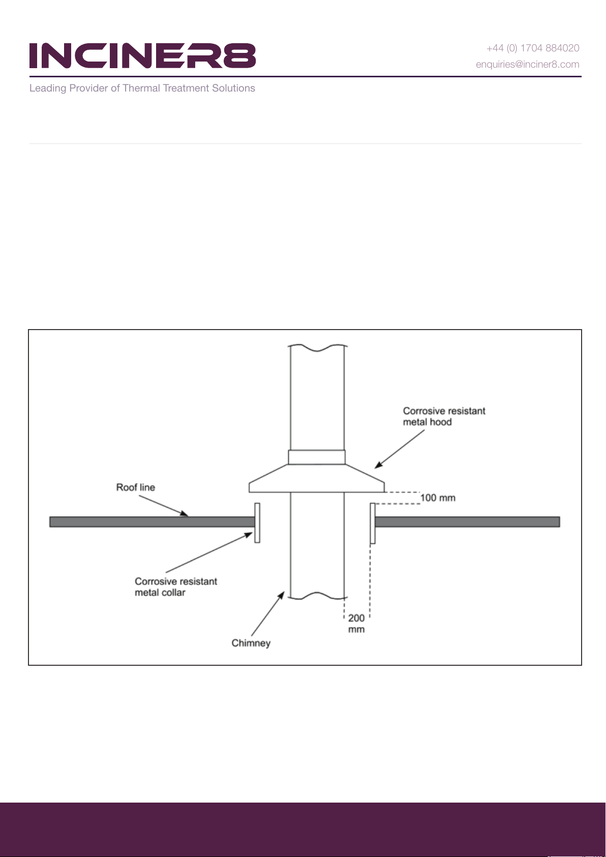
If the building has a roof, provision will need to be made to allow the chimney to pass through with weather protection as
shown on next drawing: (See APPENDIX 1 for more drawings)
All the fuel (gas or oil) supply installations must be done by approved professionals, in accordance to local regulations.
The control panel has a thermocouple attached via a 3m lead. The control panel will need siting in a suitable position
based on this 3m length. This is where power needs to go to – 230V 50Hz 10amp (if not ordered with power specica-
tions). It is the client’s responsibility to supply power and a qualied electrician to make this connection in line with local
regulations.
It is also the clients responsibility to provide suitable lifting equipment and operator to place the primary chamber and lift
the secondary chamber into place, either a forklift truck, crane or similar, suitable for 2,000 kgs can be used.
Inciner8 Limited. Company Registered in England & Wales - REG: 04866401
VAT Registration: 855999544
Enter the world of:
www.inciner8.com
+44 (0) 1704 884020
Leading Provider of Thermal Treatment Solutions
Assembly
STEP 1 - Connection of Main Parts
a). Find suitable location for the primary chamber.
b). Attach the stack cap to the chimney using the 4 tech
screws supplied.
c). Using the Fire Cement supplied put a thick beads of
the gasket sealant around the refractory lining on the
outlet of the secondary chamber.
d). Insert chimney and stack cap on the secondary
chamber outlet at securely fasten with 8 M10x20
anged bolts and nuts.
e). Using the re cement put a thick bead of sealant
around the outlet of the primary chamber.
f). Lift the secondary chamber on the primary chamber
ensuring the burner mount is facing the same direction
as the primary burner mount.
g). Use the 8 m10x20 anged bolts and nuts to securely
fasten the secondary chamber to the primary.
h). Attach latch handle with 4 bolts (M8x20)

Inciner8 Limited. Company Registered in England & Wales - REG: 04866401
VAT Registration: 855999544
Enter the world of:
www.inciner8.com
+44 (0) 1704 884020
Leading Provider of Thermal Treatment Solutions
Assembly
STEP 2 - Connecting the Burners
a). In the primary burner box take out the 4 studs and insert in the 4 holes in the primary burner mount.
b). Repeat the above process for the secondary burner.
c). Remover the mounting plate and gasket from the burner and attach to the studs using the 4 nuts in the burner box.
d). Repeat the above process for the secondary burner.
e). With the burner mount attached the burner can be slotted back on the mount and tighten the retainer nut.
f). Repeat the above process for the secondary burner.
g). On both burner pumps remove the bolt labelled P and insert the pressure gauges supplied in the burner boxes using
sealant tape which is not supplied.
h). Connect the fuel pipes to both primary and secondary burner following the piping diagram found in the manual.

Parameter
Inciner8 Limited. Company Registered in England & Wales - REG: 04866401
VAT Registration: 855999544
Enter the world of:
www.inciner8.com
+44 (0) 1704 884020
Leading Provider of Thermal Treatment Solutions
Assembly
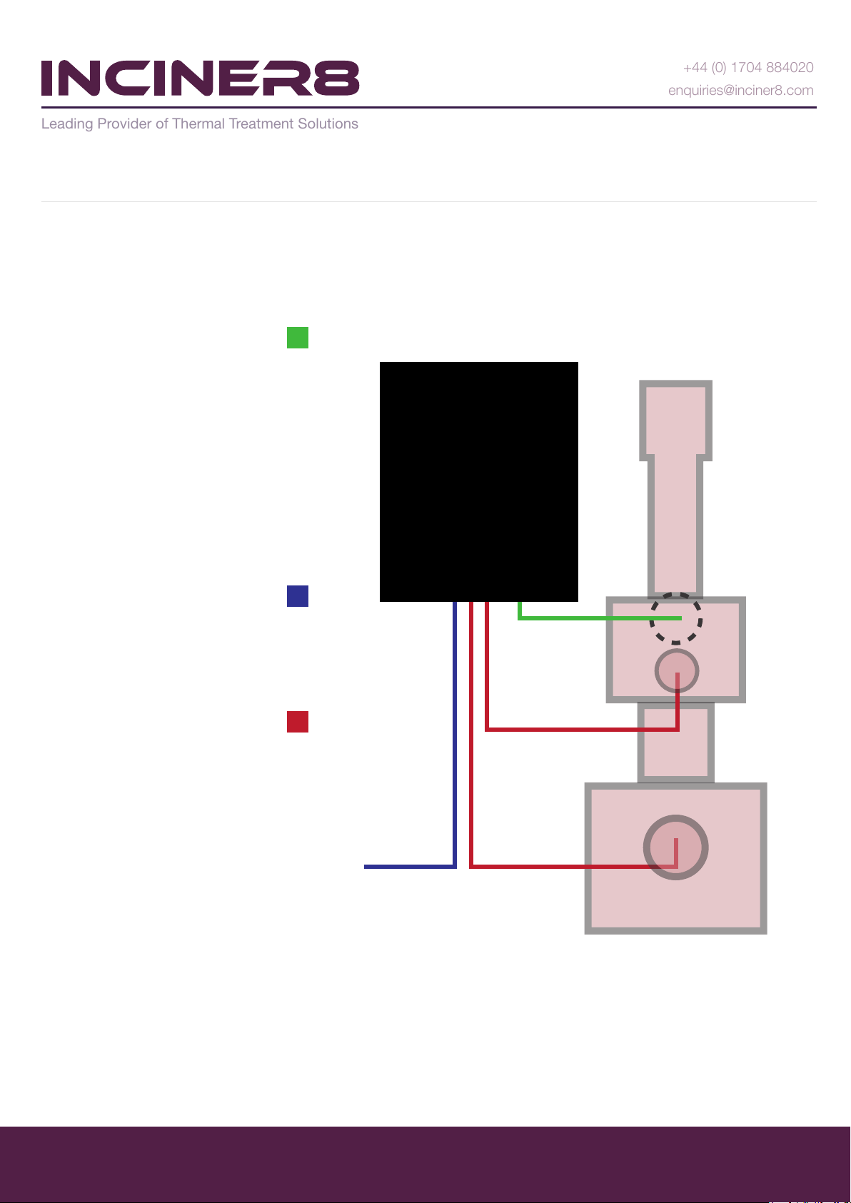
STEP 3 - Connecting the Control Panel & Thermocouple
Thermocouple Port
This is located near the rear of the
chimeny stack.
a). Choose location for control panel and ensure there is enough cable length to reach each burner and the
thermocouple can reach the thermocouple port.
b). Attach the cable from the control panel to the burners, the primary cable is labelled PRIM and should go to the
primary burner and the secondary cable is labelled SEC and will go to the secondary burner. Insert and tighten the
thermocouple to the thermocouple port.
c). Make sure the control panel has a power supply and follow the instructions for the curing process.
Parameter
Inciner8 Limited. Company Registered in England & Wales - REG: 04866401
VAT Registration: 855999544
Enter the world of:
www.inciner8.com
+44 (0) 1704 884020
Leading Provider of Thermal Treatment Solutions
Assembly
STEP 3: Control Panel Model: CE2
Thermocouple.
This is to be screwed into the port
located at the top of the secondary
chamber just beneath the chimney
ange.
Ensure the end of the thermocouple
is centrally located in the chimney
and not touching the concrete.
Electrical connection.
Single phase 10amp connection
required. Connection to be made by
a qualied electrical engineer.
Burner connection port.
Use appropriate burner plugs from
the control panel to connect primary
and secondary burner.
Burner plugs are marked as
PRIMARY (for primary chamber
burner) and SECONDARY (for
secondary or afterburner)
Please remember
All our products are designed to operate on 240v mains supply. Please ensure you use the right voltage when operating
this equipment.
Make sure the control panel has a power supply and follow the instructions for the refractory
curing process.
Choose location for control panel and ensure there is enough cable length to reach each
burner and the thermocouple can reach the thermocouple port.

Inciner8 Limited. Company Registered in England & Wales - REG: 04866401
VAT Registration: 855999544
Enter the world of:
www.inciner8.com
+44 (0) 1704 884020
Leading Provider of Thermal Treatment Solutions
Assembly
STEP 3 - Gas Connections
Please consult an experienced and qualied gas engineer before attempting any gas installations.
ONLY A QUALIFIED GAS
ENGINEER CAN CARRY OUT
THIS STEP. DO NOT ATTEMPT
THIS IF YOU ARE
IN-EXPERIENCED
Please note
You will need to connect these hoses to the fuel supply using 1/4” BSP (British Standard Pipe) male ttings, the supplied
hoses have 1/4” BSP female ttings. Ensure fuel supply is sufcient to give fuel pump feeding pressure of 12-15 bar
when using light oil.

Inciner8 Limited. Company Registered in England & Wales - REG: 04866401
VAT Registration: 855999544
Enter the world of:
www.inciner8.com
+44 (0) 1704 884020
Leading Provider of Thermal Treatment Solutions
Assembly
STEP 3 - Oil Connections
Please consult an experienced and qualied engineer before attempting any fuel installations.
ONLY A EXPERIENCED
ENGINEER CAN CARRY OUT
THIS STEP. DO NOT
ATTEMPT THIS IF YOU
ARE IN-EXPERIENCED
Please note
You will need to connect these hoses to the fuel supply using 1/4” BSP (British Standard Pipe) male ttings, the supplied
hoses have 1/4” BSP female ttings. Ensure fuel supply is sufcient to give fuel pump feeding pressure of 12-15 bar
when using light oil.
Inciner8 Limited. Company Registered in England & Wales - REG: 04866401
VAT Registration: 855999544
Enter the world of:
www.inciner8.com
+44 (0) 1704 884020
Leading Provider of Thermal Treatment Solutions
Assembly
STEP 4 - Fuel Connections
Connect the 2 – Flexible PTFE fuel hoses (within the burner box), 1 for ow, 1 for return. Light oil ow return setup - Two
pipe system example for 2 burners
Please note
Flow & Return
example
You will need to connect these hoses to the fuel supply using 1/4” BSP (British Standard Pipe) male ttings, the supplied
hoses have 1/4” BSP female ttings. Ensure fuel supply is sufcient to give fuel pump feeding pressure of 12-15 bar
when using light oil.
Parameter
Inciner8 Limited. Company Registered in England & Wales - REG: 04866401
VAT Registration: 855999544
Enter the world of:
www.inciner8.com
+44 (0) 1704 884020
Leading Provider of Thermal Treatment Solutions
Assembly
STEP 4 - Fuel Connections
Connect the 2 – Flexible PTFE fuel hoses (within the burner box), 1 for ow, 1 for return. Light oil ow return setup -
Single pipe system example for 2 burners
Please note
Flow & Return
example
You will need to connect these hoses to the fuel supply using 1/4” BSP (British Standard Pipe) male ttings, the supplied
hoses have 1/4” BSP female ttings. Ensure fuel supply is sufcient to give fuel pump feeding pressure of 12-15 bar
when using light oil.
It is imperative that the refractory concrete within the unit is cured prior to use. Failure to do so will void the warranty and
may damage the machine. Please ensure that the air/fuel ow settings on the burner are set correctly (the ame should
be clean without any black smoke) and fuel pipework is free from leaks. During this process, it is normal to have
steam/water coming out of the incinerator.
Burners can be turned on/off from control panel. To start curing process, set primary airow to 3.5 and secondary airow
to 1. Please note that only primary burner should be turned on and secondary burner must be permanently off during this
exercise.
Curing is carried out using the following temperature set points as ordered in the procedures below;
Inciner8 Limited. Company Registered in England & Wales - REG: 04866401
VAT Registration: 855999544
Enter the world of:
www.inciner8.com
+44 (0) 1704 884020
Leading Provider of Thermal Treatment Solutions
Refractory Curing
YOU MUST FOLLOW THIS PROCESS
Advice
Following the curing process, you will see hairline cracks and minor scaling in the concrete which is completely normal.
Cracks wider than 2 mm should be treated using High Temp Black Mastic.
Congratulations, your incinerator is now cured.
Set Temperature 100°C Primary Burner ON 5 Minutes Primary Burner OFF15 Minutes
Set Temperature 100°C Primary Burner ON 5 Minutes Primary Burner OFF15 Minutes
Set Temperature 200°C Primary Burner ON 15 Minutes Primary Burner OFF15 Minutes
Set Temperature 200°C Primary Burner ON 15 Minutes Primary Burner OFF15 Minutes
Set Temperature 300°C Primary Burner ON 30 Minutes Primary Burner OFF15 Minutes
Set Temperature 300°C Primary Burner ON 30 Minutes Primary Burner OFF15 Minutes
Set Temperature 400°C Primary Burner ON 60 Minutes Primary Burner OFF15 Minutes
Set Temperature 400°C Primary Burner ON 60 Minutes Primary Burner OFF15 Minutes
Set Temperature 400°C Primary Burner ON 120 Minutes Primary Burner OFF15 Minutes
Set Temperature 450°C Primary Burner ON 60 Minutes
Set Temperature 500°C Primary Burner ON 60 Minutes
Set Temperature 550°C Primary Burner ON 60 Minutes
Set Temperature 600°C Primary Burner ON 60 Minutes
Set Temperature 650°C Primary Burner ON 60 Minutes
Set Temperature 700°C Primary Burner ON 60 Minutes
Set Temperature 750°C Primary Burner ON 60 Minutes
Set Temperature 800°C Primary Burner ON 60 Minutes
Set Temperature 850°C Primary Burner ON 60 Minutes

Parameter
Inciner8 Limited. Company Registered in England & Wales - REG: 04866401
VAT Registration: 855999544
Enter the world of:
www.inciner8.com
+44 (0) 1704 884020
Leading Provider of Thermal Treatment Solutions
Fault Finding
Please check before contacting us about any issues
Black scorch marks on the
incinerator body
Thermocouple failure
Steam from the incinerator
during the curing process
Small cracks within the
refractory concrete
Large cracks
Burner ame appears to turn
up the chimney
Flames from the chimney
"Booming" noise from the
incinerator during operation
Smooth appears from the
joint of the incinerator body
and top
Control Panel displays
"0000"
Grey/white smoke
Black smoke
Burner issues
Leakage from damaged re
rope or misaligned door
Excessive temperature or
corrosion from waste gases or
uids
Water within the refractory
concrete
Expansion/contraction whilst
heating/cooling
Wear & tear
Too much draw from chimney
Too much ammable waste in
the main chamber
Main chamber overlled or air
setting too high
Mastic sealing joint is
damaged
Thermocouple failure resulting
from loose connection
Temperature is too low
Insufcient oxygen in main
chamber
Replace re rope or realign door
Replace thermocouple
This is completely normal
This is completely normal
Repair with high temperature cement or
mastic
If chimney has been extended, this is too high
Reduce waste batch size
Reduce waste batch size or lower air setting
Reseal the joint with high temperature mastic
Check wiring or replace thermocouple
Increase temperature or ensure unit is
pre-heated
Reduce waste batch size. It is sometimes
better to burn smaller batches more regularly
Please refer to fault nding section in
enclosed burner manual
PROBLEM CAUSE SOLUTION

Parameter
Inciner8 Limited. Company Registered in England & Wales - REG: 04866401
VAT Registration: 855999544
Enter the world of:
www.inciner8.com
+44 (0) 1704 884020
Leading Provider of Thermal Treatment Solutions
General Operation
Incineration
Like in every combustion process in incineration it is all about providing optimal conditions for clean combustion.
Most important factors you can control are:
Air
Black smoke normally indicates lack of the oxygen in combustion process, so there is a lot of unburned carbon in the
smoke, and this is what makes it black.
Increasing air settings on the air dumper on the side of the burner will provide better air / fuel ratio, which will also
increase burn rate, but this will only help providing there is not too much waste loaded in the chamber.
Fuel (both diesel oil and waste)
You are supplying fuel to a process through burners (pumping diesel oil), and also through waste loaded into a chamber.
It is very important to have primary burner on, only for a short time, to ignite waste. Once waste starts to burn itself, turn
primary burner off. This will help you to obtain better combustion conditions, and also to save fuel.
Temperature
In case of very ammable waste, lower preheating temperature is suggested, as this will prevent all the waste material to
ash instantly, and too much energy to be released in a very short time.
Burn procedure
Please follow these instructions to define optimal batch size, air settings etc:
Repeat steps 2 - 6 above gradually increasing batch size, in order to dene maximum batch size, temperature and air
settings for a clean combustion for each waste type you are dealing with.
Most important is to have main burner on for as short time as possible (only for preheating, and waste ignition - if
needed).
Preheat incinerator using both burners with lower air settings during the preheating (main burner air dumper on 3 –
3,5) to 500 – 850 deg C. For highly ammable waste use lower preheating temperature (I.E. 350 - 400 deg C)
Stop primary burner and load small quantity of waste for a start (i.e. 5-15 kg – depends on waste type)
Start primary burner only for a short period of time (i.e 1 minute), but only if waste hasn’t ignited itself - in most
cases you will not need primary burner at all after preheating (if burning ammable waste), and increase air settings
positioning air dumper on main burner to between 6 and 8 (depends on waste type).
Turn main burner off, and If needed, add more air (increase air dumper setting on main burner).
Once waste is ignited, temperature will increase to a certain pick (depending on waste amount and caloric value)
and then, it will start decreasing (indication that it has been mostly burned).
You can now load another batch of waste (a bit more waste than in rst batch) etc ...
1
2
3
4
5
6

Parameter
Inciner8 Limited. Company Registered in England & Wales - REG: 04866401
VAT Registration: 855999544
Enter the world of:
www.inciner8.com
+44 (0) 1704 884020
Leading Provider of Thermal Treatment Solutions
General Operation
The Controller: Omron E5CC
To change set point value
Press up (5) or down (4) arrows as required, left arrow (3) moves digit position
Digit being changed will ash, after 3 seconds change is made
To Change Hysteresis
Hysteresis is the the variable allowance that the burn will burn or stop
Press button 1
Adjust hysteresis value as required.
Preset value is 25°C
To return to home page, press button 1
PV = Present temperature value from the thermocouple
SV = set point value for desired burn temperature
PV
SV
22
800
PV
SV
HYS
25.0
PV
SV
WIoN
40.0
PV
SV
WIoN
40.0
PV
SV
1 2 3 4 5
Press button 1 ( HYS displayed )
Press button 2 (WloN displayed) –
adjust burn time here
Using arrow keys (4,5) adjust
desired burn time
Once the ashing stops the
control panel needs to be reset for
the new time to start. Turn
SYSTEM to OFF and then ON, the
new time will now start.
When heater output is activated,
“OUT1” is displayed in yellow.
When burn time is complete,
“STOP” is displayed in yellow.
ONOFF
SYSTEM
To Change Burn Time

Parameter
Inciner8 Limited. Company Registered in England & Wales - REG: 04866401
VAT Registration: 855999544
Enter the world of:
www.inciner8.com
+44 (0) 1704 884020
Leading Provider of Thermal Treatment Solutions
Maintenance
Pre-start checks
Ensure re rope, loading door and ash removal door seals are in good condition.
Check the condition of the refractory concrete lining. Repair any large cracks/holes.
Check fuel supply is clear and not restricted. Electrical connections are safe and secure.
Check exterior metal work. Treat any corroded sections immediately.
Check the thermocouple is working correctly.
Monthly checks
To keep your unit in good working condition, please carry out the following checks each month:
Damage to the re rope under the lid
Visible damage to the chimney
Visible damages to the outside body of the incinerator
(corrosion of metal parts, discolorations, leaks)
Condition of temperature probe
Condition of fuel and electrical installation
Service procedures (every 1 year or 1000 working hours)
Your unit must be routinely serviced to stay in good working condition. Servicing should take place
once a year (or after 1000 hours usage, whichever comes rst). The following checks and mainte-
nance should be carried out:
Replace re rope under the lid
Do parallel measurement of temperature probe (if regulated by law)
The burner should be serviced by an approved professional
Check sealing between each individual part of chimney (including secondary chamber)
Clean metal parts of incinerator, and re-spray if needed
All burners should also be routinely serviced by an approved professional
Please remember
You (the customer) must keep logs of all service procedures carried out, with
detailed comments where applicable.
Table of contents
Popular Industrial Equipment manuals by other brands

Interroll
Interroll SH 1210 Installation and operating instructions

ALENCON
ALENCON SPOT BOX v2 user manual

Belmash
Belmash SDM-2000 operating manual

PAW
PAW MB3.10 Assembly, installation and operation instructions

Busch-Jaeger
Busch-Jaeger Busch-Wachter DualLINE 6813/11 Series operating instructions

Precision Rated Optics
Precision Rated Optics OFS-943V Operation guide


