Incra Miter 5000 User manual

Manufactured by Taylor Design Group, Inc. P.O. BOX 810262 Dallas, TX 75381 ©2016 by Taylor Design Group, Inc. All rights reserved.
Before using the INCRA Miter5000, read and follow all of the instructions and safety information in this owner’s manual.
°When using the INCRA Miter5000 in conjunction with any other tool, first read and follow all instructions and safety information
in that tool’s owner’s manual.
° Never let the saw blade come in contact with the aluminum or steel components of the INCRA Miter5000.
° Before making any cut, always make sure that the Miter5000’s Sled Base Right is locked securely in the right hand miter slot.
° When using the INCRA Miter5000, always keep your hands clear of the saw blade and the line of cut.
° Always turn offthe power and make sure that the saw blade comes to a complete stop before changing the setting of any part of the
INCRA Miter5000.
° Always securely tighten the large black clamping knob before starting any cut.
° Wear safety glasses, hearing protection, and follow all normal shop safety practices.
° After making any adjustments to the miter angle or fence position of your INCRA Miter5000, always verify safe clearance between
the blade and fence before turning on the saw.
° After making any adjustments to the fence position on the INCRA Miter5000, always make sure that the four socket head screws on
the fence mounting bracket and the outboard fence lock are securely tightened.
° When using the INCRA Flip Shop Stop to position a piece for a cut, always hold or otherwise clamp the board between the stop and
the blade.
OWNER’SMANUAL
www.incra.com
Important safety instructions for using the INCRA Miter5000
Before using the INCRA
Miter5000, read and follow
all of the instructions and
safety information in this
owner’s manual.
by
SAFETY

INCRA MITER5000 OWNER’S MANUAL
Manufactured by Taylor Design Group, Inc. P.O. BOX 810262 Dallas, TX 75381 WWW.INCRA.COM
Page 2
PARTS LIST
Carefully Unpack Components
After carefully unpacking all components, remove the (2) Phillips at head screws and rectangular nuts that secure the (2)
Miter Sled base panels and steel miter bar. Also, remove the Phillips head screw that secures the aluminum miter bar to
the protractor head. Fig. 1 depicts the components you should have received. Identify each part as listed below:
Fig. 1 Parts List
Fig. 2 Conversion for Right Side of Blade
Fig. 3 Fully Assembled View - Right Side of Blade
A
Hex bolt
32” Flip Fence
Extender Bar
Steel Miter Bar
Aluminum Miter Bar
3/16” Ball End Hex Tool
Large Clamping Knob
Left Sled Base w/Protractor
Head Assembly
Hardware Pack C-08
Hardware Pack C-07
Hardware Pack C-05
Right Sled Base
Build-It Clamp
Owner’s Manual
Flip Shop Stop
4” Flip Fence Extender
LEFT OR RIGHT SIDE OF BLADE?
Your new Miter 5000 is factory congured for use on the
left side of your blade. This conguration works well with
right hand blade tilt table saws. If you have a right tilt table
saw proceed directly to the instructions starting on page 3.
If you have a left hand blade tilt table saw, the Miter 5000
can be converted for use on the right side of the blade.
Just follow the instructions below.
Remove the hex bolt and the 1/4 x 3/4 pivot shoulder bolt
and washers that secure the protractor head to the miter
sled and lift the protractor top and bottom plates off. (Re-
tain the 1/2” o.d. steel washer located in the recess on the
sled base for reassembly.) Next remove the (4) Phillips at
head screws that secure the Miter 5000 mounting plate as-
sembly to the bottom of the sled base. Now re-assemble
the mounting plate assembly and protractor onto the op-
posite side of the sled base. Be sure to place the 1/2” o.d.
steel washer in the recessed hole on the sled base before
re-mounting the protractor. See Fig. 2.
You can now continue using the assembly instructions. Just
remember that you are setting up the unit for use on the
right side of the blade. During assembly, when the owner’s
manual makes reference to the right miter slot, perform
the assembly instruction in the left miter slot. Converse-
ly, when the owner’s manual calls for the left miter slot,
perform the assembly instruction in the right miter slot.
A set of reverse reading scales is included for use when
later assembling the fence to the protractor. Refer to Fig. 3
to maintain proper orientation during assembly.
IMPORTANT - PLEASE READ BEFORE ASSEMBLY
A
B
C
D
E
F
G
H
I
J
K
L
M
N
O
B
C
D
E
FGHI
O
N
M
L
K
J
Miter 5000
mounting plate
Retain washer for use
in recess on left side of
panel
Pivot shoulder
bolt

INCRA MITER5000 OWNER’S MANUAL
©2016 by Taylor Design Group, Inc. All rights reserved. Rev.6.16
Page 3
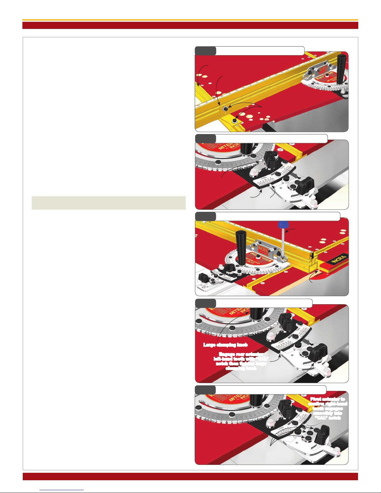
1. Adjust the Steel Miter Bar
Open hardware pack C-07 and using the supplied 3/32”
hex key, adjust the miter bar at each of the (5) expansion
mechanism locations (white disks only) for a good t in
your table saw’s left hand miter slot. Turning the screw
clockwise expands the mechanism. Expand a little at each
of the locations until the bar slides smoothly with no side
play. You can thread the large clamping knob into the bar
while adjusting to aid in sliding the bar in your miter slot,
Fig. 4. If the miter slot in your table saw has a T-slot,
attach the T-clip to the end of the bar as shown in Fig. 5.
2. Attach Left Sled Base to Miter Bar
Using (3) #10-24 x 3/4” at head Phillips screws, attach the
left sled base to the steel miter bar. To access the rear
mounting hole position, remove the hex bolt that secures
the protractor head and disengage the rear actuator tooth
from the 1/2° adjustment plate. (Retain the large washer
for use with the large clamping knob.) Pivot the protractor
head for access to the rear mounting hole and tighten all
(3) fasteners, Fig 6. Check the sliding motion of your sled
base now and adjust before continuing.
Tip: Future ne adjustments to the miter bar’s
expansion mechanisms can be made through
the access holes in the sled base left. Pivot the
protractor head as described above for access
to the rear expansion location.
3. Install Large Clamping Knob
Pivot the protractor head to rmly re-engage the left
hand tooth of the rear actuator with the 0° notch on
the 1/2° adjustment plate and tighten the thumbscrew.
Place the large washer retained in step 2 on the large
clamping knob and thread through the slotted hole in the
protractor head into the sled base left. Before tightening,
engage the front actuator tooth with the 0° notch on the
protractor head. Tighten the front actuator thumbscrew,
then the large clamping knob, Fig 7.
4. Attach Sled Base Right and Cut-off Overhang
Using (7) #10-24 x 1/2” at head Phillips screws, attach
the sled base right to the panel connector on the sled
base left. Raise your saw blade about 3/4” and make a cut
to remove the portion of the sled base right that extends
to the right of the blade, Fig. 8. Turn off the saw, lower
the blade and remove the sled base left from the table
saw.
5. Adjust Aluminum Miter Bar
Using the supplied 3/32” hex key, adjust the aluminum
miter bar at each of the (2) expansion mechanism loca-
tions for a good t in your table saw’s right hand miter
slot. Turning the screw clockwise expands the mecha-
nism. Expand a little at each of the locations until the bar
slides smoothly with no side play, Fig. 9.
Fig. 6 Attach Left Sled Base to Miter Bar
Miter bar
Fig. 4 Adjust Steel Miter Bar
Adjust each of the (5)
white expansion disks
ASSEMBLY
10-24x1/4
Phillips at
head screw
T-clip
Miter bar
Fig. 5 Attach T-Clip
#10-24x3/4 Phillips
at head screws
Remove hex bolt
Retain washer
Fig. 7 Install Large Clamping Knob
Rear
actuator
Large clamping knob
1/2°
adjustment
plate
Front actuator
Washer
Fig. 8 Attach Sled Base Right and Cut-off Overhand
#10-24x1/2 Phillips
at head screws
(7 places)
Cut to remove right
side overhang
Retain washer
Fig. 9 Adjust Aluminum Miter Bar
Adjust expansion
mechanisms

INCRA MITER5000 OWNER’S MANUAL
Manufactured by Taylor Design Group, Inc. P.O. BOX 810262 Dallas, TX 75381 WWW.INCRA.COM
Page 4
6. Attach remainder of Sled Base Right and Cut-
off Overhang
Using (4) #10-24 x 3/4” at head Phillips screws, attach the
remainder of the sled base right to the aluminum miter bar.
Use the mounting holes that permit the least amount of
overhang beyond the left side of the saw blade. Raise the
saw blade about 3/4” and make a cut to remove the por-
tion of the base right that extends beyond the left side of
the blade, Fig. 10. Turn off the saw, lower the blade and
return the sled base left to the table saw.
In use, only the sled base left slides to move your workpiece
through a cut. The sled base right will be positioned adja-
cent to the blade and locked in place by tightening the (2)
expansion mechanisms to provide zero clearance and work-
piece cutoff support, Fig. 11. Additional base right panels
can be purchased and cut as described above with the blade
tilted for zero clearance support during compound mitering.
Just mark each of the panel parts with the blade tilt angle for
future reference.
7. Attach Fence and Fence Extender to Sled
Base Left
Open hardware pack C-08 and using (2) 1/4-20 x 1/2” sock-
et head screws with washers and rectangular nuts, attach
the fence to the fence mounting bracket. Slide the fence
to a position that leaves safe clearance between the fence
and blade then tighten the (2) fasteners, Fig. 12. Loosely
install (1) 1/4-20 x 3/8” socket head fastener with washer
and rectangular nut to the left end of the fence and slide
extender bar into fence with the scale face up. (The higher
numbers on the scale should go in rst.) Loosely install (2)
1/4-20 x 3/8” socket head screws with washers and rect-
angular nuts to the 4” fence extender and slide onto the
end of the extender bar. Position the 4” fence extender
ush with the end of the extender bar and tighten all (3)
fasteners, Fig 13.
About your Fence Scales
All INCRA products use overlapping 16” long Lexan scales.
The overlap allows ne-tuning the scale from one end to the
other to agree with the high degree of accuracy provided by
the INCRA saw toothed positioning racks. As they are slid
into the scale slot on the fence, the ends are overlapped
and aligned using the optical window located at the end of
the second scale. The friction t will keep the scales in
place. If you wish, you can use a small piece of double faced
tape at the overlap to ensure that the scales move together
when changing your zeroed setups for mitering.
Fig. 11 Sled Base Panel Functions
Always lock right base
in place by tightening expansion
mechanisms
Fig. 13 Attach Extender Bar and 4” Fence Extender
1/4-20x3/8” socket
head screws
4” Fence extender
Fig. 12 Attach Fence to Protractor
Position fence for
safe clearance
1/4-20x1/2” socket
head screws
TIP
Fig. 10 Attach Sled Base Right and Cut-off Overhang
Cut to remove left side
overhang
#10-24x3/4” Phillips
at head screws
Extender bar
Flush
here
Overlap scales as you slide
into scale slot
Optical window used
for proper alignment
TIP
INCRA MITER5000 OWNER’S MANUAL
©2016 by Taylor Design Group, Inc. All rights reserved. Rev.6.16
Page 5
8. Attach Outboard Fence Lock
Loosen the large clamping knob, disengage the front ac-
tuator and pivot the fence just over the left rear corner
of the sled base, (about 20°). Loosely install (1) 1/4-20 x
1/2” socket head screw with washer and rectangular nut
through the hole in the outboard fence lock. Slide the re-
maining 1/4-20 x 1/2” socket head screw with washer and
rectangular nut into the T-slot on the back of the fence.
Slide the slotted end of the outboard fence lock under the
washer on the fence fastener then slide the rectangular
nut of the other fastener into the T-slot on the gold panel
connector, Fig. 14. Rotate the fence to engage the front
actuator with the 0° notch on the protractor head. Tight-
en the front actuator thumbscrew then tighten the large
clamping knob.
CALIBRATION
1. Adjust Fence Mounting Bracket 90° to Cut
Edge of Sled Base Left
Loosen the large clamping knob and make sure that the rear
actuator left hand tooth is engaged rmly with the 0° notch
on the 1/2° adjustment plate. Engage the front actuator
tooth with the 0° notch located on the protractor head,
Fig.15. Tighten the front actuator thumbscrew then tight-
en the large clamping knob.
Using a Phillips head screw driver, loosen the (3) Phillips
head screws that secure the fence-mounting bracket to the
protractor head. Unplug your table saw, then use a reliable
machinist square to set the fence at 90° to the cut right hand
edge of the sled base, Fig. 16. Tighten the (3) Phillips head
screws. This one time calibration prepares your INCRA
Miter5000 for work. Just remember that the accuracy of
the INCRA Miter5000 at any subsequent setting is depen-
dent upon the accuracy of your initial 90° calibration. After
completing the Calibration and Operation sections of this
manual, verify this important calibration with a test cut and
ne tune as necessary.
2. Calibrating the 1/2° Indexing Tooth
The 1/2° indexing tooth located on the rear actuator is fac-
tory calibrated and should require no further adjustment.
Follow the instructions below should you wish to check the
calibration or re-calibrate.
Loosen the large clamping knob and the rear actuator
thumbscrew. Engage the left-hand tooth of the rear actua-
tor rmly with the notch marked “CAL” on the rear scale
and hold while you tighten the large clamping knob, Fig. 17.
Now pivot the rear actuator to engage the right- hand tooth
with the notch marked “CAL” on the rear scale, Fig. 18. If
adjusted properly, it will pivot perfectly into the notch. To
adjust, loosen the (3) socket head screws that secure the
tooth and ne tune the position to align with the “CAL”
notch. Pivot back and forth between the two “CAL” notch-
es to verify the calibration.
Fig. 15 Lock Front and Rear Actuator to 90°
Front actuator
tooth
Fig. 14 Attach Outboard Fence Lock
Outboard fence lock
1/4-20x1/2” socket
head screws
In operation, after setting the protractor head angle and
tightening the large clamping knob, you must tighten the
outboard lock to the fence before tightening to the sled
base. Try setting a few angles to get the hang of it, then
leave both outboard lock fasteners loose as you continue
with the nal calibration.
Fig. 16 Square Fence to “Cut” Edge of Sled Base
Square fence to
edge of sled
Fig. 17 Calibrating 1/2° Indexing Tooth
Large clamping knob
Fig. 18 Pivot Actuator to Check Calibration
Loosen (3) socket
head screws to adjust
if necessary
Panel connector
1/2° adjustment
plate Rear actuator
left-hand tooth
Loosen (3) Phillips head
screws
Engage rear actuator
left-hand tooth with “CAL”
notch then tighten large
clamping knob
Rear actuator thumbscrew
Pivot actuator to
conrm right-hand
tooth engages
smoothly into
“CAL” notch
INCRA MITER5000 OWNER’S MANUAL
Manufactured by Taylor Design Group, Inc. P.O. BOX 810262 Dallas, TX 75381 WWW.INCRA.COM
Page 6
Fig. 20 5° Indexing - Re-engage Front Actuator
1st: Rotate to
desired angle
Fig. 19 5° Indexing - Disengage Front Actuator
2nd: Loosen front
actuator thumb-
screw and pivot
tooth away from
protractor
1st: Loosen large
clamping knob
Fig. 21 1/2° Indexing - Engage Front Actuator
3rd: Tighten
thumbscrew
Fig. 22 1/2° Indexing - Engage Rear Actuator
3rd: Tighten large
clamping knob and rear
actuator thumbscrew
Left-hand tooth of rear
actuator at 0°
2nd: Engage front actu-
ator tooth with notch at
desired angle
2nd: Loosen front actuator
thumbscrew and engage
tooth with 5° notch closest
to your desired angle
1st: Loosen rear
actuator thumbscrew
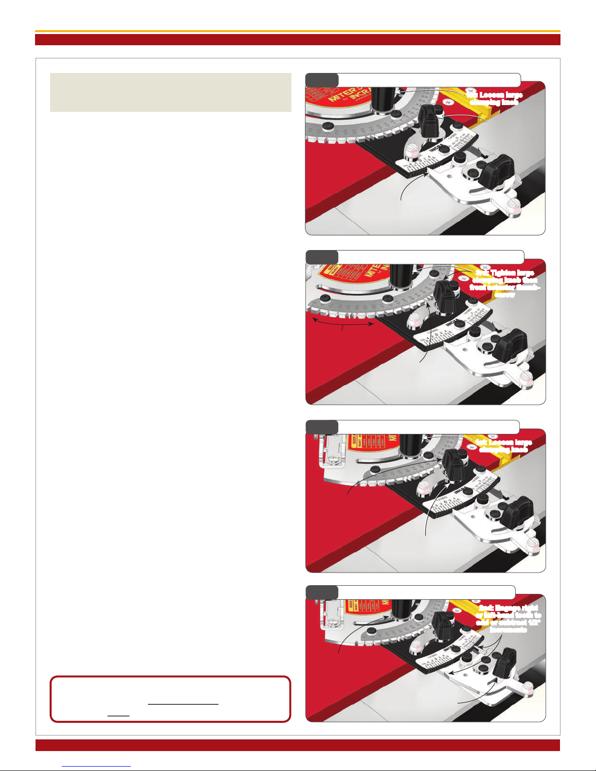
OPERATION
- CHANGING ANGLE SETTINGS
The dual actuator design of the INCRA Miter5000 provides
two levels of adjustment. The front actuator is used for
coarse adjustments (5°), while the rear actuator is used for
ne adjustments (1/2°). For most mitering work, you’ll have
the left-hand tooth of the rear actuator engaged at the 0°,
while you make angle changes using only the front actua-
tor. When using the rear actuator for ne adjustments, you
are simply adding or subtracting from the coarse adjustment
setting.
5° Indexing (including 22.5 and 67.5°) settings
1. Loosen the large clamping knob and make sure that the
rear actuator left hand tooth is engaged in the 0° notch on
the 1/2° adjustment plate. Loosen the front actuator thumb-
screw and pivot the actuator tooth away from the notches
located on the protractor head, Fig. 19.
2. Rotate the protractor head to the desired angle then
rmly engage the tooth on the front actuator with the cor-
responding notch on the protractor head. The actuator
tooth should point directly to the desired angle on the scale.
Tighten the large clamping knob, then tighten the front actu-
ator thumbscrew, Fig. 20.
1/2° Indexing
1. Loosen the large clamping knob. Loosen the front actua-
tor thumbscrew and pivot the actuator tooth away from the
notches located on the protractor head. Rotate the protrac-
tor head and engage the front actuator tooth at the 5° notch
closest to the angle you want. Tighten the front actuator
thumbscrew, Fig. 21.
2. Loosen the rear actuator thumbscrew. Use the left-hand
tooth to add or subtract from the coarse adjustment setting
in 1° intervals. Use the right-hand tooth to add or subtract
from the coarse adjustment setting in 1/2° intervals. En-
gage the tooth rmly in the selected notch then tighten the
large clamping knob and the rear actuator thumbscrew, Fig.
22. Important: After completing your cut don’t
forget to return the rear actuator setting to the
0° notch.
Continuous Adjustments
For angle settings ner than the 1/2° settings, rst use the
1/2° indexing instructions above to locate the protractor
head as close as possible to the desired angle. With the
large clamping knob loosened, pivot the rear actuator tooth
slightly away from the notch on the 1/2° adjustment plate.
Rotate the protractor head in the direction of required ad-
justment and tighten the large clamping knob. Do not tight-
en the rear actuator thumbscrew. As with any mitering tool,
odd angle adjustments may require a little trial and error.
Caution: After making any adjustments to the miter angle of your
INCRA Miter5000, always verify safe clearance between the fence
and the blade before turning on the saw.
3rd: Tighten large
clamping knob then
front actuator thumb-
screw
1st: Loosen large
clamping knob
2nd: Engage right
or left-hand tooth to
add or subtract 1/2°
increments
INCRA MITER5000 OWNER’S MANUAL
©2016 by Taylor Design Group, Inc. All rights reserved. Rev.6.16
Page 7
Fig. 23 Flip Shop Stop
Tongue and groove
Fig. 24 Zeroing Fence Scale
Protractor set to 0°
Fig. 26 Setting Scales for Angled Cuts
Slide scale to read
cut length here
Measure length
of cut
FLIP FENCE AND FLIP SHOP STOP
- CALIBRATION AND OPERATION
As you look at your new INCRA Flip Shop Stop and Flip
Fence for the rst time you will see an interesting detail.
The front face of the fence uses a tongue and groove
arrangement to accept a mating feature on the ip arms,
Fig. 23. When the ip arm is down with the two opposing
features engaged, it becomes impossible for the sharp cor-
ner of a mitered board end to wedge between the fence
and ip arm. Combined with INCRA’s famous incremental
positioning capabilities, you’ll soon be duplicating cut off
lengths with machine shop precision.
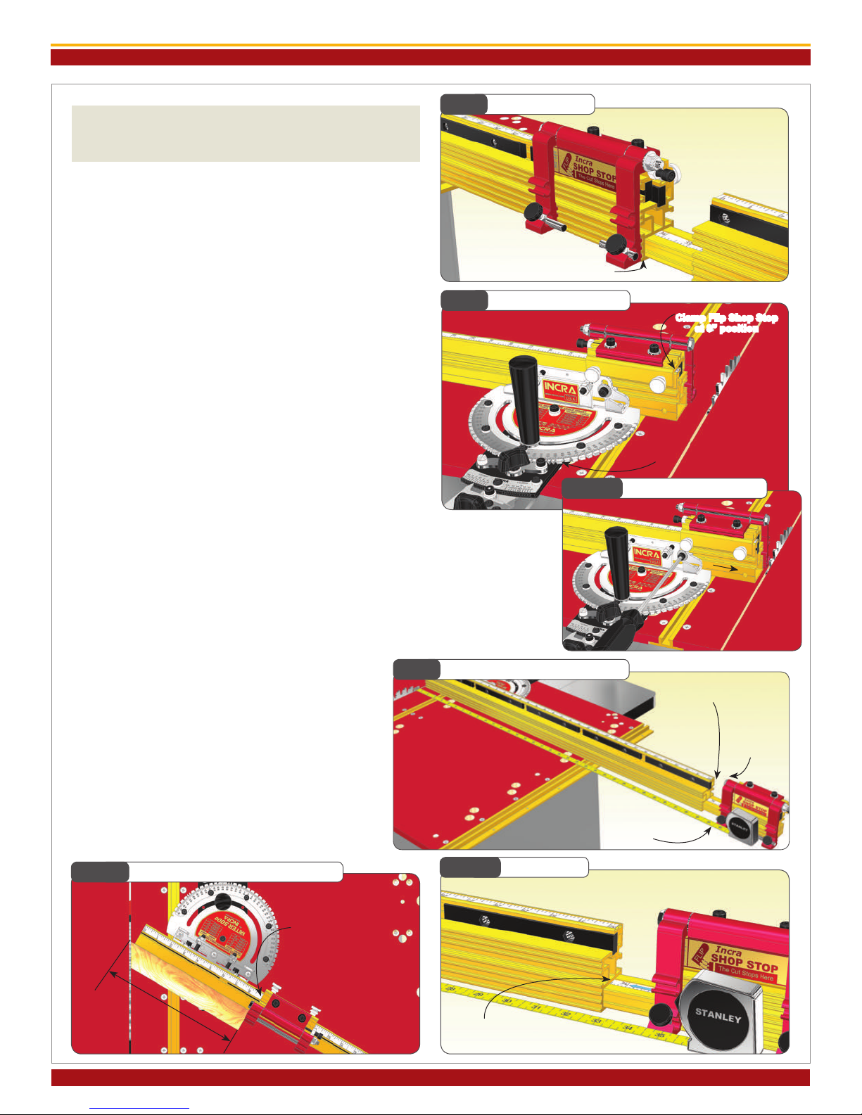
Zeroing the Fence Scales
To zero the main fence scale for 90° work, rst set the
protractor to the 0° setting and lock in place. Clamp
the Flip Shop Stop to the fence so that the 0” mark on
the fence scale reads directly under the end of the gold
component of the Flip Shop Stop, Fig. 24. Now loosen
the (2) 1/4-20 socket head screws that secure the fence to
the fence mounting bracket and slide the fence toward the
blade until the Flip Arm on the stop contacts the blade.
Re-tighten the fasteners, Fig. 24A.
For stopped cuts beyond the range of the main fence you’ll
need to calibrate the extender bar scale. Clamp the IN-
CRA Flip Shop Stop to the 4” fence extender. (Use the scale
on the short section of fence as a reference for clamping
the stop to the same position each time you use it.) Now
loosen the 1/4-20 socket head screw located at the end of
the longer fence and slide the 4” fence and extender bar
out. Use a tape measurer to set the distance between the
blade and the Flip Arm at 34-1/2” and re-tighten the fasten-
er, Fig. 25. Now simply slide the scale in the extender bar
to read 34-1/2” at the end of the longer main fence section,
Fig. 25A.
For mitered cutting, a test cut is often the most ac-
curate means of setting the fence and extender bar
scales since measuring to the tooth of a blade set at
an angle to the fence can be difcult. Begin by setting
the desired miter angle and check for safe clearance
between the fence and blade. Clamp the stop to the
fence about 10” away from the blade. Miter a piece
of scrap stock with this setup. Measure the length of
the cut piece, Fig. 26. Then simply slide the scale on
the fence to read the length of the cut directly under
one end of the stop.
Fig. 24A Slide Fence to Blade
Fig. 25A Align Scale
Clamp Flip Shop Stop
at 0” position
Slide fence until
ip arm contacts blade
then tighten fasteners
Fig. 25 Setting Extender Bar Scale
Loosen extender
bar fastener
Clamp stop to
4” section
Slide extender bar out until ip
arm is 34-1/2” from blade then
tighten fastener
Slide scale to read 34-1/2”
at the end of main fence
©2016 by Taylor Design Group, Inc. All rights reserved. Rev.6/16
Page 8
Manufactured by Taylor Design Group, Inc. P.O. BOX 810262 Dallas, TX 75381 WWW.INCRA.COM
MADE IN THE
USA
Taylor Design Group, Inc. P. O . B OX 810 2 6 2 D a l l as , T X 75 3 81 P : 9 72 -2 42 - 9 9 75 F : 9 72 -2 4 2 - 9 9 85 www.incra.com
INCRA is a Registered Trademark of Taylor Design Group, Inc. ©2016 Taylor Design Group, Inc.
INCRA MITER5000 OWNER’S MANUAL
Fig. 27 Micro Adjusting
Fig. 29 Making a Sub-Fence
Loosen (2)
socket head screws
Turn this socket
head screw to
adjust
2-1/2” max
(see note)
Fig. 30 Expanded Flip Stop Clamping Mode
Slide red assembly
into 2nd T-slot on gold
component
1/4-20
rectangular nut
Loosen socket
head screws
Fig. 28 Short Stop Rods
Short stop
rods allow
independent
ip arm use
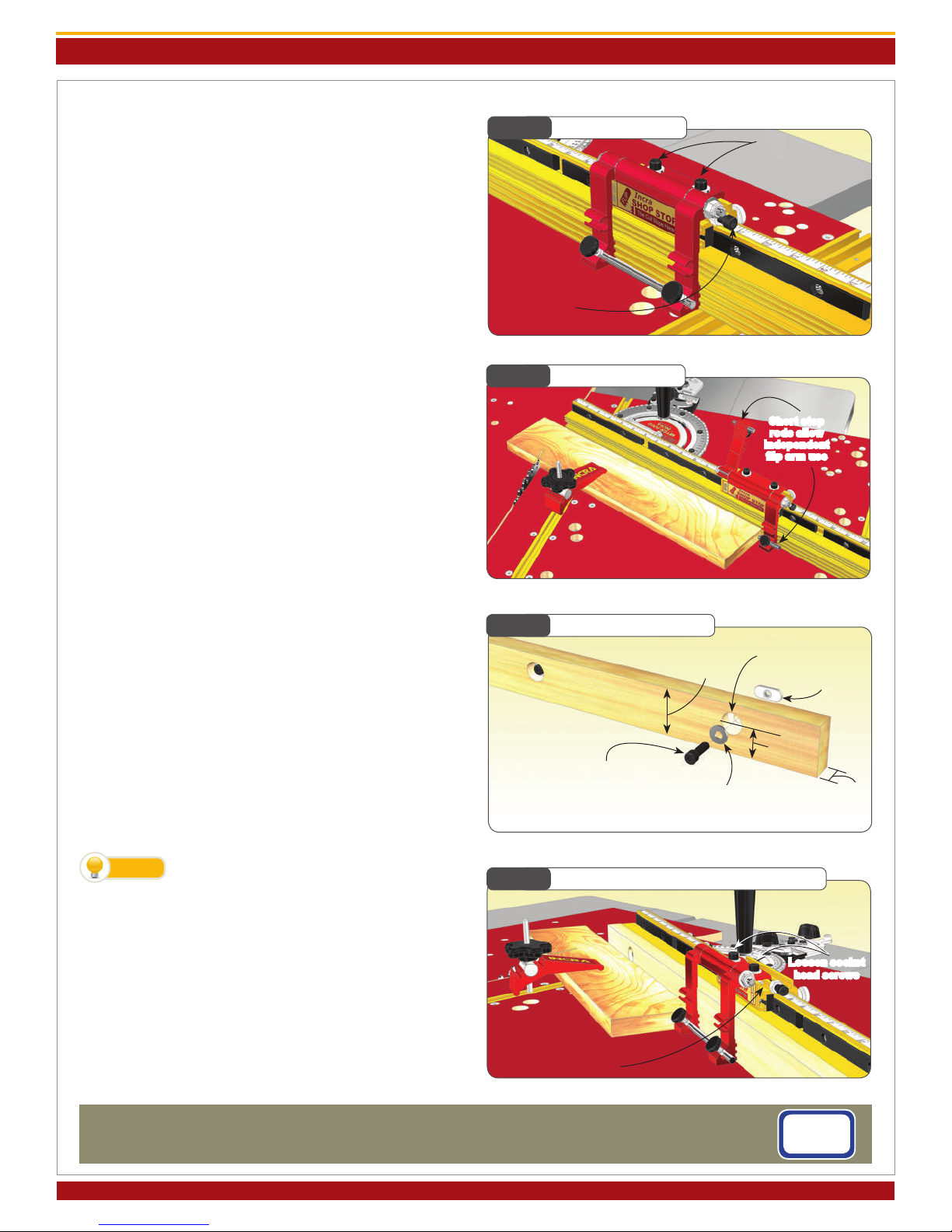
Micro Adjusting
To micro adjust your Flip Shop Stop’s position, begin by
loosening the (2) socket head screws located on the top
of the stop body. Now turn the micro adjust socket head
screw to ne tune the stop position, Fig. 27. When un-
screwing the micro adjust screw, apply pressure to the stop
body to keep it against the screw end. After adjustment,
always tighten the (2) socket head screws on top of the
stop body.
Flip Arms and Stop Rods
The dual ip arms and stop rods provide a variety of stop
congurations. The ip arms can be used without the stop
rods when you want to take advantage of the fence/arm
tongue and groove feature for stop control on mitered
board ends. Typically, you will use the longer rod to join
the two arms together. This produces an arrangement
that, when pivoted, moves both arms simultaneously. The
rod can be positioned so that it is the actual stop surface
or it can be positioned slightly behind the front of the arm
so that the aluminum arm is the actual stop surface.
By placing one of the shorter 1-1/2” rods in each of the two
stop arms, you can use the two stop arms independently,
Fig. 28. For example, you can calibrate one for work to
the left of the blade and the other for work to the right.
On one side of the blade you might want to position the
stop rods to provide two different cut off lengths from one
stop position. By using varying combinations of long or
short rods you can create as much as 7-3/4” between the
two stop positions.
Making a Zero Clearance Wooden Sub-Fence
A sub-fence can be used to provide tear out control as well
as support for your workpiece up to and beyond the blade.
A good material to use for making your zero clearance sub-
fence is 3/4” medium density berboard (MDF). Use the
drill and counter bore dimensions shown in Fig. 29. Attach
using the supplied fasteners. Adjust the length of the fence
to accommodate your application. Note: In applications
where the incremental stopping capability of the Flip Shop
Stop is required, the wooden sub-fence can be no taller
than 2-1/2”.
To avoid the saw blade pulling your work-
piece into the cut, add a strip of adhesive
backed sandpaper to the front face of the wooden sub-
fence.
Expanded Flip Stop Clamping Mode
The two-part body design of the INCRA Flip Shop Stop al-
lows for use with up to a 3/4” thick wooden sub-fence. To
expand the INCRA Flip Shop Stop, loosen the (2) socket
head screws located on the top of the stop body, then slide
the upper portion of the stop off. Now slide the upper
portion back on, capturing the rectangular nuts in the sec-
ond T-slot located on the lower portion (gold component)
of the stop body, Fig. 30.
TIP
1/4-20x3/4” socket head
screw 1/4 at washer
1-1/16”
3/4”
5/16” through hole w/ 3/4”
dia. x 3/8” deep counter bore
Table of contents
Popular Cutter manuals by other brands

Safety Speed Manufacturing
Safety Speed Manufacturing 72GP owner's manual

Romus
Romus LP 650 Operation manual

Bms Bulut Makina
Bms Bulut Makina BULUCUT-6 Operational manual

Bosch
Bosch POF 1400 ACE Original instructions

ARCBRO
ARCBRO Stinger-PRO 5100 Series Install manual

Roller
Roller King 1 1/4 operating instructions


