Index Braille Index V4 User manual

© 2011 Enter your company name
V4 Service
manual
2011-03-29


IContents
© 2011 Enter your company name
Table of Contents
Model Disassembly instructions 1
................................................................................................................................... 11 Electronic modules Everest and Basic
................................................................................................................................... 12 Basic D
......................................................................................................................................................... 1Remove back plate
......................................................................................................................................................... 1Remove side covers
......................................................................................................................................................... 1Replace embossing head
......................................................................................................................................................... 1Replace Main Board
......................................................................................................................................................... 2Replace Paper Tractors
......................................................................................................................................................... 2Replace motor module
......................................................................................................................................................... 2Remove the fan
................................................................................................................................... 23 Everest D
......................................................................................................................................................... 3Clear major paper jam
......................................................................................................................................................... 3Remove front glass
......................................................................................................................................................... 3Remove back plate
......................................................................................................................................................... 3Remove side covers
......................................................................................................................................................... 3Replace sheet feeder
......................................................................................................................................................... 3Replace main board
......................................................................................................................................................... 4Replace embossing head
......................................................................................................................................................... 4Replace roller module
................................................................................................................................... 44 Braille Box
......................................................................................................................................................... 5Open the Service door
......................................................................................................................................................... 5Remove Braille tray
......................................................................................................................................................... 5Dismounting Braille Box
.................................................................................................................................................. 5Plates
........................................................................................................................................... 5Top plate
........................................................................................................................................... 5Mid plate back
........................................................................................................................................... 5Mid plate le t
........................................................................................................................................... 6Technical corner plate
........................................................................................................................................... 6Right lower cover plate
........................................................................................................................................... 6Inner ront plate
........................................................................................................................................... 6Braille tray cover plate
........................................................................................................................................... 6Braille tray guides
.................................................................................................................................................. 6Mechanical modules
........................................................................................................................................... 6Front glass door
........................................................................................................................................... 6Embossing tower
........................................................................................................................................... 7Replace embossing head
........................................................................................................................................... 7Replace roller module
........................................................................................................................................... 7Replace paper out lip lop
........................................................................................................................................... 7Replace ventilation module
......................................................................................................................................................... 8Sheet feeder
.................................................................................................................................................. 8Replace pick up roller
.................................................................................................................................................. 8Replace sheet eeder
......................................................................................................................................................... 8Electronic modules
.................................................................................................................................................. 8Replace CPU BCP V4
.................................................................................................................................................. 8Replace Driver PCB V4
.................................................................................................................................................. 8Replace Sheet eeder PCB V4
.................................................................................................................................................. 8Replace LED PCB V4
.................................................................................................................................................. 9Replace Power supply
.................................................................................................................................................. 9Replace an
V4 Service manualII
© 2011 Enter your company name
......................................................................................................................................................... 9
Sensors
.................................................................................................................................................. 9Re lectiv light Sensor All V4
General Service tasks 10
................................................................................................................................... 101 Embossing head
......................................................................................................................................................... 10Replace hammer
......................................................................................................................................................... 10Replace anvils
................................................................................................................................... 102 Power supply Specification
......................................................................................................................................................... 10Basic and Everest
......................................................................................................................................................... 11Braille Box
................................................................................................................................... 113 Electornic PCB, cables
......................................................................................................................................................... 11Main Board PCB V4
......................................................................................................................................................... 14Braille Box Electronics
.................................................................................................................................................. 16Braille Box CPU PCB V4
.................................................................................................................................................. 16Braille Box Driver PCB V4
.................................................................................................................................................. 17Braille Box Top Connection PCB
.................................................................................................................................................. 17Braille Box Sheet Feeder PCB V4
.................................................................................................................................................. 17Braille Box LED PCB V4
......................................................................................................................................................... 17ATC Braille & Print PCB
................................................................................................................................... 174 Fuse
LED feedback 18
................................................................................................................................... 181 Braille Box LED
Appendix 19
................................................................................................................................... 191 Esc sequences
Specifications 21
................................................................................................................................... 211 Basic D V4
................................................................................................................................... 222 Everest D V4
................................................................................................................................... 223 Braille Box V4
Service information sources 23

1Model Disassembly instructions
© 2011 Enter your company name
1 Model Disassembly instructions
1.1 Electronic modules Everest and Basic
Enter topic text here.
1.2 Basic D
Enter topic text here.
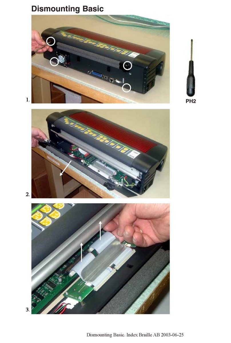
1.2.1 Remove back plate
•Open the 2 knurled thumb screws at the bottom holding the back plate
•Remove the back plate
1.2.2 Remove side covers
•Remove the 3 screws which holding the cover rom each side
•Place the Basic-D upside down and remove the 2 rubber eet holding each panel
•Remove the side cover
1.2.3 Replace embossing head
Remove embossing head
•Remove back plate, see instructions
•Remove the embossing head axle metallic locking ring with a lat screw driver
•Disconnect the embossing head cable
•Release the embossing head locking ring (motor side) rom the side panel and pull the axle
against you
•Remove the embossing head, locking ring and axle
Insert embossing head
•Place the embossing head with its locking ring on the axle, le t side.
•Place the right side o the axle in the holder on the speaker side cover
•Li t the plastic spring with your inger.
•Placed the embossing head on the print head motor gear wheel, at the same time click in axle
into the cover (speaker side)
•Place the locking ring in position
•Move the embossing head by hand to check the mechanical movement
•Connect the embossing head cable
•Close the back plate - see instruction
1.2.4 Replace Main Board
Remove Main Board
•Remove the back plate - see instruction.
•Remove embossing head - see instruction.
•Remove all cables rom the Main Board
Cables to: Embossing head cable, Embossing head motor, Paper movement motor, Paper
sensor 1, Paper sensor 2 and Front panel.
•Pull the main board top edge out, until it releases rom the 4 metallic clips
•Remove the Main board

2 V4 Service manual
© 2011 Enter your company name
•Remove the SD memory card rom the aulty main board.
The Index SD memory card includes embosser speci ic parameters like serial number, number
o embossed pages, page ormat, embosser settings, etc.
Insert Main Board
•Insert the original SD memory card rom the previous main board to the new main board
•Place the new main board in position and make sure it clips in OK
•Connect all cables (see picture)
•Insert embossing head - see instruction
•Connect main board cable
•Insert back plate - see instruction
1.2.5 Replace Paper Tractors
•Remove the back plate - see instruction
•Remove the embossing head - see instruction
•Remove motor side cover - see instruction
•Remove the 3 screws holding locking ring or the tractor eed square axle and remove the axle
•Remove the round axle ( lat screw driver) by turning it CCW Contra Clock Wise.
•Disconnect the two paper sensors
•Remove the ormula tractors
(PHOTO Position o square axle - dots on the tractor)
When inserting new ormula tractors, please note the position o the small dots near the hole or
the square axle. These marks has to be on the same side o the square axle.
1.2.6 Replace motor module
•Remove the back plate - see instructions
•Remove the embossing head - see instructions
•Remove the side cover - see instructions
•Disconnect 2 motor cables
•Unscrew the 6 screws holding the motor module
•Remove the motor module
1.2.7 Remove the fan
•Remove the back plate - see instruction.
•Remove the embossing head - see instruction
•Remove side cover - see instructions
•Disconnect the 4 screws holding the an rom the motor module
•Remove the an
1.3 Everest D
Enter topic text here.

3Model Disassembly instructions
© 2011 Enter your company name
1.3.1 Clear major paper jam
•Remove the ront glass - see instruction
•Cut the paper above and below the embossing head with a sharp thin kni e (switch blade kni e).
Avoid the rubber rollers.
•Remove and clear the the embossing head rom jammed paper
•Rotate the rollers or checking and removing jammed paper
•Remove embossing head - see instructions
•Clean the embossing head rom jammed paper
1.3.2 Remove front glass
•Remove the 2 knurled thumb screws rom the glass
•Press the glass down
•Remove the glass by li ting it up
1.3.3 Remove back plate
•Remove the our screws holding the back plate (picture with our screws)
•Li t up the back plate by twisting a lat screw driver between the lower center o the plate and
aluminum pro ile
•Li t up the back plate care ully
1.3.4 Remove side covers
•Remove the ront glass
•Remove the back plate
•Remove the side covers
- 8 screws on le t side cover (top ront = smaller 3.5x13)
- 7 screws on right side cover
1.3.5 Replace sheet feeder
•Remove the two screws on the top o the sheet eeder
•Li t up the sheet eeder
•Disconnect the sheet eeder cable
1.3.6 Replace main board
•Remove back plate - see instruction
•Release the main board rom the 4 upper click connectors
•Remove all cable rom the main board
•Tilt the main board to a 45 degrees angle
•Li t the main board towards you.
•Remove the SD memory card rom the aulty main board.
The Index SD memory card includes embosser speci ic parameters as or example: serial
number, number o embossed pages, page ormat, embosser settings.
When inserting a new main board please Insert the original SD memory card be ore powering on
the unit.

4 V4 Service manual
© 2011 Enter your company name
1.3.7 Replace embossing head
REMOVE EMBOSSING HEAD
•Remove ront glass - see instructions
•Remove the Embossing head locking ring (le t side)
•Release the embossing head axle by pulling le t side (locking ring side) towards you
•Remove the embossing head rom the embosser
•Disconnect the embossing head cable
REPLACE EMBOSSING HEAD
•Insert the embossing head axle in the embossing head
•Insert the embossing head locking ring on the embossing head axle with the larger diameter
side against the plate
•Connect the embossing head cable please note the direction (picture)
•Insert the right side o the embossing head axle in the holder
•Li t the plastic spring which holds down the embossing head with a screw driver, at the same
time push the print head+axle in position between the stepper motor gear wheel and plastic
spring.
•Insert the le t side o the embossing head axle in the holder by pressing it towards the embosser
until it click in position
•Press the embossing head locking ring to the le t against the holder
•Move the embossing head by hand to check the mechanical movement
•Insert the ront glass - see instructions
1.3.8 Replace roller module
•Remove the ront glass - see
•Remove the back plate - see
•Remove motor side cover - see
•Remove the paper movement driving belt rom gear belt wheel on the roller axle
•Remove the 4 screws holding the roller module bearing
•Take out the roller module by sliding it out
1.4 Braille Box
Open issues, this will be completed when tested on the prototypes.
Service tasks:
Clearing paper jam
Remove/insert embossing head
Replace paper sensor
Paper tray
Remove Braille
Check paper out lip lop mechanism
Check paper
Braille tray
Technical corner
Top plate

5Model Disassembly instructions
© 2011 Enter your company name
1.4.1 Open the Service door
1. Open the Braille out tray
2. Open the lock on the right side o the service door by rotating it by hand
3. Open the Service door
1.4.2 Remove Braille tray
1. Open the Braille tray
2. Release the plastic locks on the Braille tray guides, right = down, le t = up
3. Remove the Braille tray rom the guides
1.4.3 Dismounting Braille Box
Enter topic text here.
1.4.3.1 Plates
Noise sealing
The corners between the outside plate, inner ront plate and technical corner plate is sealed with
silicone.
A ter working with this plates it is necessary to re-seal them again. Please add silicon sealing in the
same way as originally shipped rom Index Braille.
1.4.3.1.1 Top plate
•Remove the Service door: see
•Remove the Braille tray: see
•Disconnect 1 cables the speaker
•Disconnect the ront panel lat cable
•Disconnect 2 cables to lip lop
•Disconnect 1 cable to the LED
•Remove the cables rom acoustic damping material
•Unscrew 9 black screws on the black inner ront plate
•Unscrew 3 screws on mid plate back
•Unscrew 5 screws on mid plate le t
•Li t up the top plate.
1.4.3.1.2 Mid plate back
•Remove the Top plate: see instructions
•Unscrew 4 screws connected Inner ront plate
•Unscrew 4 screws connected to Technica corner
•Unscrew 3 screws connected to Bottom plate
•Li t up the Mid plate back
1.4.3.1.3 Mid plate le t
•Remove the Top plate: see
•Unscrew 4 screws connected Inner ront plate
•Unscrew 4 screws connected to Technica corner
•Unscrew 5 screws connected to Bottom plate

6 V4 Service manual
© 2011 Enter your company name
•Li t up the Mid plate le t
1.4.3.1.4 Technical corner plate
•Remove the CPU Board: see
•Remove the Top plate: see
•Remove the Mid plates: see
•Remove the power plug cables
•Disconnect the cable to LED PCB
•Li t up the Technical corner plate.
1.4.3.1.5 Right lower cover plate
Unscrew 4 screws behind the Inner ront plate (x mm nyckel?)
Remove the Right lower cover plate
1.4.3.1.6 Inner ront plate
Remove the Top plate: see
Remove the Mid plates: see
Remove the Braille tray: see
Remove the Right lower cover plate
Unscrew xx? screws at the lower edge o the Inner ront plate
Li t up the Inner ront plate. It may be connected with silicon sealing. Care ully remove the silicon
mechanically
1.4.3.1.7 Braille tray cover plate
Enter topic text here.
1.4.3.1.8 Braille tray guides
•Remove the Braille tray: see
•Unscrew the 8 screws holding the Braille tray guides against the sheet eeder
•Remove the Braille tray guides
1.4.3.2 Mechanical modules
Enter topic text here.
1.4.3.2.1 Front glass door
Release the hinges with a lat screw driver (Picture?)
1.4.3.2.2 Embossing tower
•Remove the Top plate: see
•Remove the Mid plates: see
•Remove the Braille tray: see
•Disconnect all cables to the Embossing tower
•Unscrew the 4 rubber connections with (xx mm ast nyckel)
•Li t up the Embossing tower

7Model Disassembly instructions
© 2011 Enter your company name
1.4.3.2.3 Replace embossing head
REMOVE EMBOSSING HEAD
•Open the service door - see
•Remove the Embossing head locking ring (picture)
•Release the embossing head axle by pressing it against you (picture)
•Disconnect the embossing head cable
INSERT EMBOSSING HEAD
1. Open the Braille out tray
2. Insert the embossing head axle in the embossing head
3. Insert the embossing head locking ring on the embossing head axle (Bild)
4. Connect the embossing head cable please note the direction (picture)
5. Press the plastic sprig up, to give room or the print head pro ile with gear bar during step 6-8
(Bild)
6. Insert the embossing head in the position between the stepper motor gear wheel (picture +
video)
7. Insert the right side o the embossing head axle in the holder
8. Insert the le t side o the embossing head axle in the holder by pressing it against the embosser
until it click in position
9. Press the embossing head locking ring to the le t against the holder
10.Move the embossing head by hand to check the mechanical movement
11.Close Braille out tray
12.Close the service door
1.4.3.2.4 Replace roller module
•Open the Service door - see instructions
•Remove the paper movement driving belt rom gear belt wheel on the selected roller axle
•Remove the 4 screws holding the axle bearing
•Take out the roller module
1.4.3.2.5 Replace paper out lip lop
Remove
•Remove Braille tray - see
•Disconnect the cables or both DC motors
•Unscrew the two screws holding the ront lip lop motor module and remove the motor module
and arm
•Unscrew the two screws holding the back lip lop motor module and remove the motor module
and arm
Insert
•Insert the back lip lop arm horizontally, place the motor module in position and tighten the two
screws
•Insert the ront lip lop arm horizontally, place the motor module in position and tighten the two
screws
•Connect the two cables to the lip lop motors
1.4.3.2.6 Replace ventilation module
•Open the Braille out tray
•Disconnect the 2 an cables
•Unscrew 4 screws in the technical corner rom the outside
•Unscrew 4 screws holding the ventilation module against the outer plate

8 V4 Service manual
© 2011 Enter your company name
1.4.4 Sheet feeder
Enter topic text here.
1.4.4.1 Replace pick up roller
•Remove the paper tray: see
•Pull the pick up roller against you until it clicks out o position
1.4.4.2 Replace sheet feeder
•Remove the paper tray
•Unscrew 4 screws holding the Sheet eeder rom below
•Remove the Sheet eeder
1.4.5 Electronic modules
Overview picture with all boards, cables, motors and sensors.
1.4.5.1 Replace CPU BCP V4
•Remove the two knurled thumb crews rom the CPU Board located in the technical corner
•Pull the CPU Board out rom the embosser
1.4.5.2 Replace Driver PCB V4
1. Open the Braille out tray: see
2. Remove the protection plate rom the click in holders
3. Remove all cables rom the Driver Board (picture)
4. Remove the Driver Board rom the click in holders
1.4.5.3 Replace Sheet feeder PCB V4
The Sheet Feeder PCB V4 is located on the le t side o the sheet eeder.
Remove the sheet eeder to get access to the Sheet eeder PCB, see instruction "Replace Sheet
eeder".
The sheet eeder PCB has sensors and connector to the pick up motor.
The sensors are Paper tray position in/out, paper out and or detecting paper size A4, A3, 11x8.5
inch letter, 11x17 inch and 11x11.5 inch. The paper size is presented by the clearly marked LED:s
in the ront corner o Braille Box. The DC eeding o the pick up motor is also included in the Sheet
eeder PCB.
1.4.5.4 Replace LED PCB V4
•Open the service door
•Unscrew the ront LED PCB
•Disconnect the LED PCB cable
•Remove the LED PCB

9Model Disassembly instructions
© 2011 Enter your company name
1.4.5.5 Replace Power supply
•Remove the Braille tray: see
•Remove the Back Braille tray guide: see
•Unscrew 4 screws holding the power supply rom below
•Remove the Power supply
1.4.5.6 Replace fan
•Open the Braille out tray
•Unscrew 4 screws to disconnect an
•Fan direction i blow out
1.4.6 Sensors
Enter topic text here.
1.4.6.1 Reflectiv light Sensor All V4
Use in Basic-D V4
The Paper edge sensor is displayed with the Green LED at main board
The Paper movement sensor check the movement o the pin ed holes and is displayed with the
Yellow LED on the main
Use in Everest-D V4
The Paper edge sensor is displayed with the Green LED at main board
Use in Braille Box V4
The Paper edge sensor is displayed with the Green LED at Braille Box CPU PCB
Out o paper - ront corner LED
Braille tray open - ront corner LED
Service door open - ront corner LED

10 V4 Service manual
© 2011 Enter your company name
2 General Service tasks
Enter topic text here.
2.1 Embossing head
The embossing head is designed with 6 male and 7 emale hammers. This hammers are designed
or a li e cycle above 1.000 000 000 strokes corresponding to about 1.000 000 Braille pages. Both
the tips o the hammers and the anvils is made in hardened steel or maximum li e cycle.
The most signi icant improvements in V4 embossing heads are:
•Individually easily removable hammers
•Paper is guided by aluminum pro ile, no longer any plastic pro iles
•The Embossing Head PCB V4 has click on montage and clearly marked hammer number
•The hammer number is clearly marked on the embossing head and on the Embossing Head
PCB V4
•Hammers with longer li e cycle
2.1.1 Replace hammer
•Print a hammer test page by pressing HELP+ON. It printout squares o all hammers with
corresponding number.
•Remove the embossing head PCB rom the click connectors
•Disconnect the aulty hammer cable
•Remove the hammer holder by pressing it down and sideways. See video at www.youtube.com
•Insert the new hammer in the same way
•Connect the new hammer cable to the PCB
2.1.2 Replace anvils
•Remove the 4 clips holding the anvil pro ile
•Remove the rubber strip
•Remove ALL 13 (7 emale and 6 mail) anvils
2.2 Power supply Specification
Switched power supply
Input voltage: 90-264 VAC or 135-370 VDC
Input requency range: 47-63 Hz
Output voltage: 48 V
Working temperature: 0 to +40C (32 to +104F)
Working humidity: 20% - 90% RH non-condensing
2.2.1 Basic and Everest
Switched
Power supply 160W (Mean Well GS160A48 R7B)
Output voltage: 48V
Output current: 3.34A
E iciency 94%

11General Service tasks
© 2011 Enter your company name
P
ower plug: See figure 1
Figure 1
2.2.2 Braille Box
Braille Box power supply Mean Well 600W Single Output with PFC unction
Model: HRPG-600-48
Input
Voltage range 85-264 VAC
Frequency range 47-63 Hz
AC current 8.5 A/115 V 5A/230V
Output
DC Voltage 48V
Rated Current 13A
Rated power 624W
Voltage tolerance +/- 1%
E iciency (typical) 89%
2.3 Electornic PCB, cables
G:\Projekt\Braille Box\Elektronik\Shema-KP
2.3.1 Main Board PCB V4
Internal connectors
P1 = Embossing head
P2= Stepper motor paper eed
P4 = Stepper Motor embossing head
P5 = Front Panel
P7 = Fan
P9 = Paper edge sensor Everest/Basic/Braille&Print
P27 = Paper jam sensor Basic
P10 = Sheet eeder Everest/Braille&Print
P14 = Speaker
C300 = Battery CR2032
External Connectors
J1 = Power in 48V
J6 = Service serial port
J5 = Serial port
P16 = USB inter ace
J2 = Network inter ace
J3 = Micro SD Memory (4GB)

12 V4 Service manual
© 2011 Enter your company name
J4 = Headphone connector
SW1 = Reset quick press/ 5 seconds = System reset
LED 1 - internal only or development
LED 2 - Green Paper sensor
LED 3 - Yellow Paper jam sensor Basic-D
Development ports, switch etc not for public use!
P21 = Internal programming port. (Pin x-2 -> changed power up unction)
SW2 = Boot strap loader (Development)
SW3 = Reset (Development)
P17 = Connector to Braille & Print
P28 = Connector to Braille & Print
P15 = Development port
P11 = Development port
P19 = Not used port

13General Service tasks
© 2011 Enter your company name

14 V4 Service manual
© 2011 Enter your company name
2.3.2 Braille Box Electronics
Connection schematic o Braille Box boards, sensors and motors.

15General Service tasks
© 2011 Enter your company name

16 V4 Service manual
© 2011 Enter your company name
2.3.2.1 Braille Box CPU PCB V4
Internal Connectors clearly specified
Bus cable connector to Braille Box Driver PCB V4
Micro SD Memory (4MB?)
Connectors Specified
Network inter ace
USB inter ace
Headphone connector
Keys
SYSTEM RESET on the backside o the embosser
- Reset (so tware)
- System reset press the key or more than 5 seconds
RESET
- Reset - (Hardware).
BOOT STR
Internal bottom should only be used by Index Braille Service. It is used or reloading the internal
boot strap loader which controls the programming o the embosser.
2.3.2.2 Braille Box Driver PCB V4
Pictures on the boards with:
Internal Connectors clearly specified
Bus cable connector to Braille Box CPU PCB V4
Bus cable to Braille Box Top Connection PCB Vr
Stepper Motor low embossing head
Hammers embossing head low
Hammers embossing head mid
Hammers embossing head high
Stepper motor paper eed 1-3
Stepper motor mid paper eed 4-5
Sheet eeder connector
Fan out connector
Fan in connector (not in use)
Paper sensor 1
Paper sensor 2 (not in use)
Connectors Specified
Power in 48V
Keys
SYSTEM RESET on the backside o the embosser
- Reset (so tware)
- System reset
RESET
- Reset - (Hardware).
BOOT STR
Internal bottom should only be used by Index Braille Service. It is or reloading the internal boot
strap loader which controls the programming o the embosser
Other manuals for Index V4
2
Table of contents
Other Index Braille Printer manuals

Index Braille
Index Braille BASIC User manual

Index Braille
Index Braille Everest-D User manual

Index Braille
Index Braille Everest-D V5 User manual

Index Braille
Index Braille Everest-D V5 User manual

Index Braille
Index Braille BASIC User manual

Index Braille
Index Braille Basic-D V5 User manual

Index Braille
Index Braille Index V4 User manual

Index Braille
Index Braille EVEREST Series User manual