Indumicro IMM-M10 S Series User manual

IMM-M10;S
PC module
User’s Manual

2
Table of Contents
Prefaces …………………………………………………….……………………………………………. 04
Revision …………………………………………………………………………………………..……………….……….. 04
Disclaimer ………………………………………………………..…….…….………………………….………………..04
Copyright Notice …………………………………….…………………….…………………………………………… 04
Trademarks Acknowledgment …………..………………………………………………………...................04
Environmental Protection Announcement …………………………….………………….……………….. 04
Safety Precautions ………………………………………….……………………………….…………….…………..05
Technical Support and Assistance …………………………………….…………….…………….…………….06
Conventions Used in this Manual ………………………………………………………………….….………..06
Package Contents …………………………………………………………………………………………….…………07
Ordering Information …………………………………….……………………………………….……….………… 07
Optional Accessory …………...……………………………………..................................................... 07
Chapter 1 Product Introductions ………………………………………………………..… 08
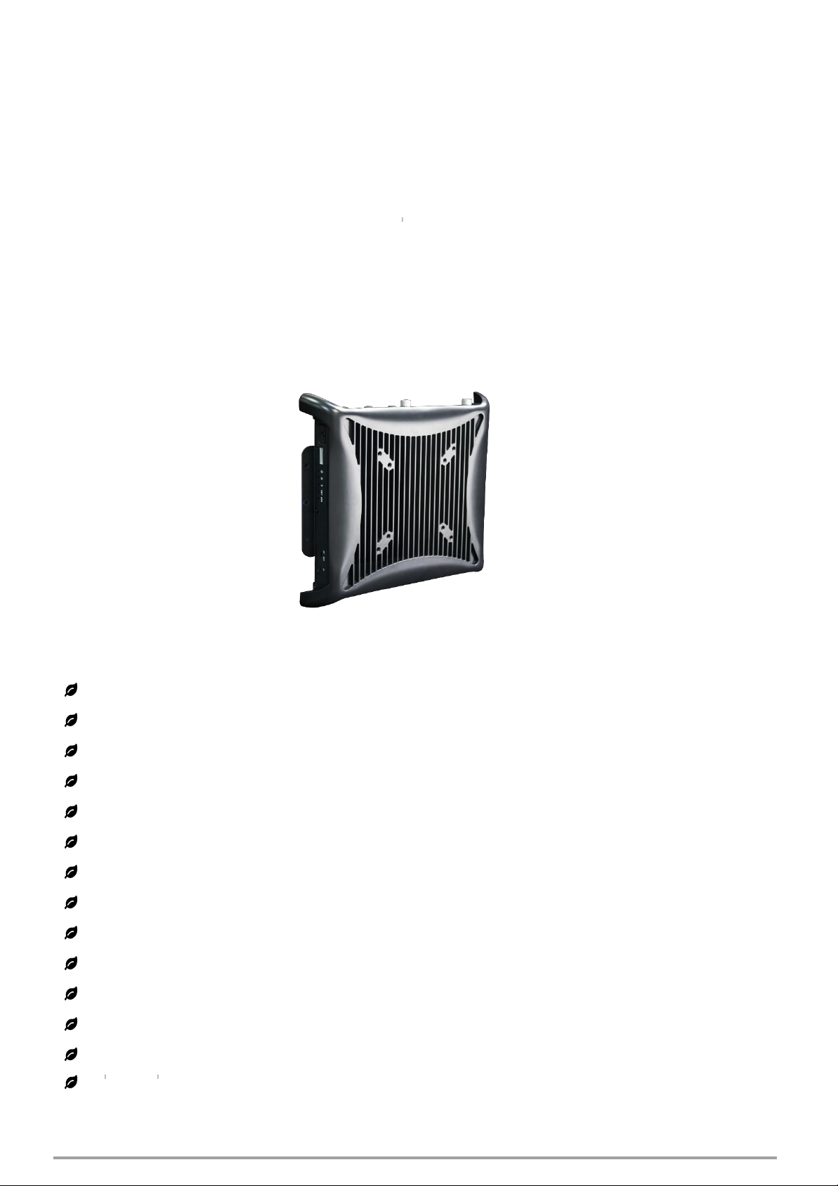
1.1 Overview ……………………….………………………………..………….………………..……….. 09
1.1.1 Key Feature ………….……………………………………….……….…..………..…....... 09
1.2 Hardware Specification ….………………………….....…………….…………..…..………… 10
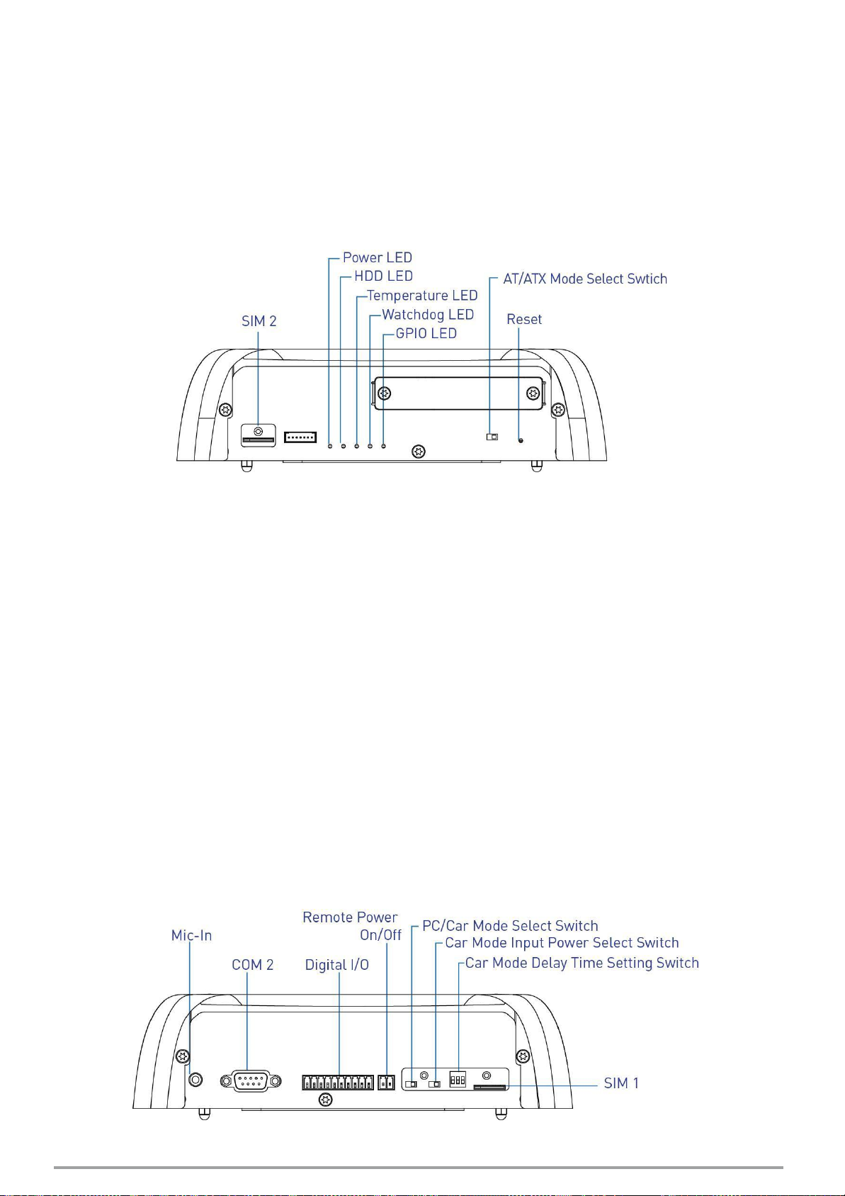
1.3 System I/O ……………………………..……………………..…………………………………..…… 11
1.3.1 IMM-M10XS ………………………………...............…..………………………….……11
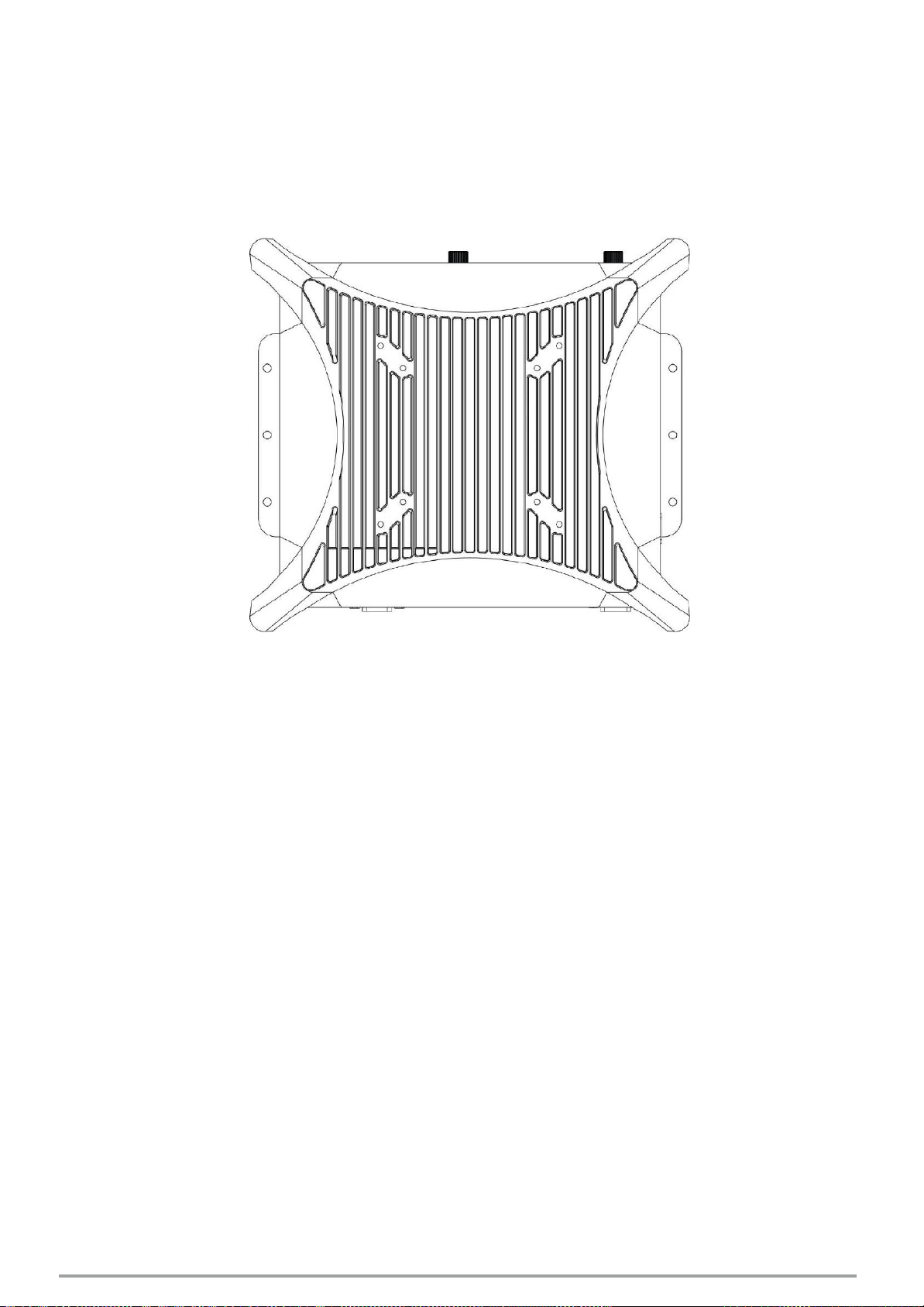
1.4 Mechanical Dimension …………………………..…………………………..………….………. 16
1.4.1 IMM-M10XS …………………………....................…………………………………… 16
Chapter 2 Switches and Connectors ……..…………………………………………..…. 18
2.1 Switch and Connector Locations ……………………………………..…….…..……..….... 19
2.1.1 Top View ……………………………………………………………………....……………… 19
2.1.2 Bottom View ……………………………………………………………………....……….. 19
2.2 Connector / Switch Definition ……………………………….……….…….………............ 20
2.3 Switch Definitions ………….…………….............................................................. 21
2.4 Connector Definitions …………………………...................................................... 23
Chapter 3 System Setup ……………………..………………………………………..……… 32
3.1 Set torque force to 3.5 kgf-cm to execute all the screwing and
unscrewing. ……….………………………………………………………………………………….... 33
3.2 Removing chassis top cover …………………………………………………..………………... 33
3.3 Installing SODIMM …………………………………………………………………………………...34
3.4 Installing mini PCIe card / mSATA ……………………………………….…………………... 35
3.5 Installing antenna ……………………………………………………………….…………………...36
3.6 Assembly chassis top cover ………………………………………………..…………………...40
3.7 Installing HDD on removable SATA HDD bay …………………………….……………... 41
3.8 Installing SIM card ……………………………………………………………….…………………...43
3.9 Connecting PC module with VIO display module ……………………..……………... 45

3
Chapter 4 BIOS Setup ……………………..……………………………………..……………. 47
4.1 BIOS Introduction ………………………………………..…….…………………………..…….... 48
4.2 Main Setup ………………………………………..…….…………….…………………………….... 49
4.2.1 System Language …….……………………………………..……..…………..……….... 49
4.2.2 System Date …….……………………………………………..……..………….……….... 49
4.2.3 System Time ………..…………………………………………..……….………..………... 49
4.3 Advanced Setup ………………………………………………………..…………………..……….. 50
4.3.1 CPU Configuration……..…………………………………………………..…..…………. 50
4.3.2 Trusted Computing (Option) ……………..…….………..…..……………..……... 51
4.3.3 ACPI Settings ……………….………..…………………………….………………..……... 52
4.3.4 Super IO Configuration ……………….………..………………..……………..……... 52
4.3.5 Hardware Monitor ……………….………..………………………….……..…..……... 55
4.3.6 Serial Port Console Redirection ……………….………..……………..…..……... 56
4.3.7 SATA Configuration ……………….………..…………………..………..……..……... 56
4.3.8 Network Stack Configuration ……………….……..…..…………………..……... 57
4.3.9 CSM Configuration ……………….………..………………………..…………..……... 58
4.3.10 USB Configuration ……………….………..…………………….……………..……... 59
4.3.11 Intel(R) Ethernet Connection I218-LM-XX:XX:XX:XX:XX:XX ….……... 60
4.3.12 Intel(R) I210 Gigabit Network Connection- XX:XX:XX:XX:XX:XX …... 61
4.4 Chipset …………...……….………………….…..….…..…………..…………………………..….... 62
4.4.1 System Agent (SA) Configuration ………………….…………..………………….. 62
4.4.2 PCH-IO Configuration ………….…………………………………..…………………….. 64
4.5 Security …………...……….………………….…..….…..………………………..……..…………... 67
4.5.1 Administrator Password …….…………………………………..…………………….. 67
4.5.2 User Password …….……………………………….………………..…………………….. 67
4.6 Boot …………...……….….………………….…..…………………………..…………..……………...68
4.6.1 Setup Prompt Timeout ………………………..…………..……………………………..68
4.6.2 Bootup NumLock State ………………………………………………..………………… 68
4.6.3 Quiet Boot ………………………….……………………….…………………..…...………. 68
4.6.4 Fast Boot …………………………..…………………………………………………………... 68
4.6.5 Hard Driver BBS Priorities …………………………..……………………….………... 68
4.7 Save & Exit …………...……….….………………………………………..…………..……………... 69
4.7.1 Save Changes and Reset …………………..…………..…………………………….. 69
4.7.2 Discard Changes and Reset ……………………………………..………………… 69
4.7.3 Restore Defaults ………………………….…………….…………………..…...………. 69
4.7.4 Launch EFI Shell from filesystem device ………………………………………... 69
Appendix WDT & GPIO ……………………………………………………………………………
70
WDT Sample Code …….……………………….……………….……………..….…….…….…………...
71
GPIO Sample Code ………………………………………………………..………………………………….
72

4
Prefaces
Revision
Revision
Description
Da
t
e
1.0
Manual Released
2017/09/12
1.1
GPIO Sample Code Revised
2018/02/09
1.2
Switches Definition Revised
2018/10/09
1.3
WDT & GPIO Sample Code Revised
2018/11/28
1.4
Switches Definition Revised
2019/03/07
Disclaimer
All specifications and information in this User’s Manual are believed to be accurate and up to date.
Indumicro.com does not guarantee that the contents herein are complete, true, accurate or non-
misleading. The information in this document is subject to change without notice and does not represent a
commitment on the part of Indumicro.com
Indumicro.com disclaims all warranties, express or implied, including, without limitation, those of
merchantability, fitness for a particular purpose with respect to contents of this User’s Manual. Users must
take full responsibility for the application of the product.
Copyright Notice
All rights reserved. No part of this manual may be reproduced or transmitted in any form or by any means,
electronic or mechanical, including photocopying, recording, or information storage and retrieval systems,
without the prior written permission of Indumicro.com Copyright © Indumicro.com
Trademarks Acknowledgment
Intel®, Celeron® and Pentium® are trademarks of Intel Corporation.
Windows® is registered trademark of Microsoft Corporation.
AMI is trademark of American Megatrend Inc.
IBM, XT, AT, PS/2 and Personal System/2 are trademarks of International Business Machines Corporation
All other products and trademarks mentioned in this manual are trademarks of their respective owners.
Environmental Protection Announcement
Do not dispose this electronic device into the trash while discarding. Please recycle to minimize pollution
and ensure environment protection.

5
Safety Precautions
Before installing and using the equipment, please read the following precautions:
Put this equipment on a reliable surface during installation. Dropping it or letting it fall could
cause damage.
The power outlet shall be installed near the equipment and shall be easily accessible.
Turn off the system power and disconnect the power cord from its source before making any
installation. Be sure both the system and the external devices are turned OFF. Sudden surge
of power could ruin sensitive components. Make sure the equipment is properly grounded.
When the power is connected, never open the equipment. The equipment should be opened
only by qualified service personnel.
Make sure the voltage of the power source is correct before connecting the equipment to the
power outlet.
Disconnect this equipment from the power before cleaning. Use a damp cloth. Do not use
liquid or spray detergents for cleaning.
Avoid the dusty, humidity and temperature extremes.
Do not place heavy objects on the equipment.
If the equipment is not used for long time, disconnect it from the power to avoid being
damaged by transient over-voltage.
The storage temperature shall be above -
40
C and below
80
C.
The computer is provided with a battery-powered real-time clock circuit. There is a danger of
explosion if incorrectly replaced. Replace only with the same or equivalent type
recommended by the manufacturer.
If one of the following situation arises, get the equipment checked be service personnel:
•The power cord or plug is damaged.
•Liquid has penetrated into the equipment.
•The equipment has been exposed to moisture.
•The equipment does not work well or it cannot work according the user’s manual.
•The equipment has been dropped and damaged.
•The equipment has obvious signs of breakage.

6
CAUTION
NOTE
WARNING
Technical Support and
Assistan
ce
1. Visit the Indumicro.com website at www.indumicro.com where you can find the latest
information about the product.
2. Contact your distributor, our technical support team or sales representative for technical support if
you need additional assistance. Please have following information ready before you call:
Model name and serial number
Description of your peripheral attachments
Description of your software (operating system, version, application software, etc.)
A complete description of the problem
The exact wording of any error messages
Conventions Used in this
Manual
This indication alerts operators to an operation that, if not strictly observed,
may result in severe injury.
This indication alerts operators to an operation that, if not strictly observed,
may result in safety hazards to personnel or damage to equipment.
This indication provides additional information to complete a task easily.

7
Package Contents
Before installation, please ensure all the items listed in the following table are included in the package.
Item Description Q’ty
1 IMM-M10XS Series PC Module
1
2 Utility DVD Driver
1
3 Screw Pack
1
Ordering Information
Model No. Product Description
IMM-M105S PC Module for Industrial Display System with Intel® i5-5350U Processor
IMM-M103S PC Module for Industrial Display System with Intel® i3-5010U Processor
IMM-M102S PC Module for Industrial Display System with Intel® Celeron® 3765U
Processor
Optional Accessories
Model No. Product Description
IMA-PSM1260 Adapter AC/DC 12V 5A 60W with 3pin Terminal Block Plug 5.0mm Pitch

Chapter 1
Product Introductions

9
1.1 Overview
The IMM-M10XS series PC module is based on 5th Gen. Intel® Core™ i5-5350U (2.9GHz) / i3-5010U
(2.1GHz) or Celeron® 3765U (1.9GHz) Dual Core processor. It supports Multi-Mode Display Module
(MDM) technology which makes it more flexible in system maintaining and upgrading. It also offers
modularize expansion I/O, rich connectivity interfaces, wide range (9~48V) DC power input, and high
reliability
even operating in temperature extremes (-
40
~+
70
C).
Featuring with completely cable-less designed and high functional, IMM-M10XS series are ruggedized
display systems that can operate in harsh environments and easy to install and maintain. A build in over
voltage protection (OVP), over current protection (OCP), reserve voltage protection, and wide range DC
power input makes IMM-M10XS series are safety system for all industrial applications.
IMM-M10XS
1.1.1 Key Features
Intel® Core™ Processor i5-5350U, up to 2.9GHz / i3-5010U, 2.1GHz or Celeron® 3765U, 1.9GHz
1x 204-pin DDR3L SODIMM. Max up to 8GB
1x 2.5” Removable SATA HDD bay support RAID 0,1, 5, 2x mSATA, 2x SIM socket
2x Full-size mini PCIe for communication or expansion modules
1x PCIe x4 (PC311E Only)
1x PCI (PC311P Only)
2x LAN
1x LVDS, 1x VGA, 1x DisplayPort
1x LVDS, 1x DVI-D, 1x DisplayPort (Optional)
2x External RS-232/422/485, 2x Internal RS-232/422/485
3x USB 3.0, 1x USB 2.0
4x Isolated Digital Input, 4x Isolated Digital Output
9 to 48VDC wide range power input
-
40
C to
70
C extended operating temperature

10
1.2 Hardware Specification
Processor System
•Onboard Intel® Core ™i5-5350U / Core™i3-5010U /
Celeron ® 3765U Dual Core Processor, 2.9 / 2.1 / 1.9GHz
with AMI 64Mbit SPI BIOS
Memory
•1x 204-Pin DDR3L-1333 / 1600MHz SO-DIMM
(un-buffered and non-ECC), Max. up to 8GB
Display
Triple Display
•1x LVDS, 1x VGA, and 1x DisplayPort
Expansion
•1x PCIe X4 (PC311E Only)
•1x PCI (PC311P Only)
•2x Full-size Mini PCIe Socket for Wi-Fi / GSM / Expansion
Module
•1x Universal I/O Bracket (PC311E, PC311P Only)
Ethernet
•1x Intel® i210-AT GbE LAN Port, Support Wake-on-LAN
and PXE
•1x Intel® I218-LM GbE LAN Port, Support Wake-on-LAN
and PXE
Audio
•Codec: Realtek ALC888S
•1x Mic-in and 1x Speaker-out
Watchdog Timer
•Software Programmable Supports 1~255 sec. System
Reset
Storage
•1x Removable 2.5" SATA HDD Bay
•2x Internal mSATA Slot (Shared by 2x Mini-PCIe Socket)
•2x External SIM Card Socket
•Support RAID 0, 1, 5
I/O Ports
•3x USB 3.0 Port
•1x USB 2.0 Port
•4x Isolated DI and 4x Isolated DO Port
•2x External DB9 for COM1~2, Support RS232/422/485
with Auto Flow Control
•2x Internal COM3~4, Support RS232/422/485 with Auto
Flow Control
•3x Antenna Hole
•1x AT/ATX Switch
•1x Remote Power on/off Connector
Digital Input & Output
•4x Digital Input (Source Type)
- Input Voltage (Dry Contact):
Logic 0: Close to GND
Logic 1: Open
- Input
Voltage:
Logic 0: 3V max.
Logic 1: 5V min. (DI to COM-)
•4x Digital Output
- Supply Voltage: 5~30VDC
- Sink Current: 200 mA Max. Per Channel
Power
•Support AT, ATX Mode
•1x 3-pin Terminal Block Connector with Power Input
9~48VDC
•Power Ignition Sensing
•1x Optional AC/DC 12V/5A, 60W Power Adapter
Environment
•Operating Temperature: Ambient with Air Flow:
-40 C
to
70 C
(with Industrial Grade Peripherals)
•Storage Temperature:
-40 C
to
80 C
•Relative humidity: 10%~95% (non-condensing)
Physical
•IMM-M10XS Series
- Dimension (WxDxH, mm): 246 x 220 x 42mm
- Weight: 1.68kg
Operating System
•Windows® 7
•WES7
•Windows® 8.1
•WES8.1
•Windows 10
•Linux kernel 3.X
Certifications
•CE
•FCC Class A

11
1.3 System I/O
1.3.1 IMM-M10XS
Front Panel
Removable HDD Bay
Used to inserts a 2.5”HDD device
Antenna hole
Used to connect an antenna for optional Mini-
PCIe WiFi module
Rear Panel
DC IN
Used to plug a DC power input with terminal
block
VGA
Used to connect an analog VGA monitor
DisplayPort
Used to connect a DisplayPort monitor
USB 3.0 port
Used to connect USB 3.0/2.0/1.1 device
USB 2.0 port
Used to connect USB 2.0/1.1 device
LAN port
Used to connect the system to a local area
network
Speaker-out
Used to connect a external speaker
COM port
COM1 support RS232/422/485 serial device
Side (Right)
SIM card
Used to insert SIM card
ATX power on/off switch
Press to power-on or power-off the system
Reset switch
Press to reset the system

12
Side (Left)
Mic-in
Used to connect a microphone
COM port
COM2 support RS232/422/485 serial device
Digital I/O Terminal Block
The Digital I/O terminal block supports 4 digital
input and 4 digital output
Remote power on/off switch
Used to plug a power on/off switch with terminal
block
PC/CAR mode select switch
Used to select PC or CAR power mode
12V/24V mode select switch
Used to select Car power input voltage
DELAY TIME switch
Used to select Car power turn off delay-time
SIM card
Used to insert SIM card
Top
VESA Mounting Hole
These are mounting holes for VESA mount (75x75mm and 100x100mm)

13
Side (Right)
SIM card
Used to insert SIM card
ATX power on/off switch
Press to power-on or power-off the system
Reset switch
Press to reset the system
Universal I/O Bracket
Used to customized I/O output
Side (Left)
Mic-in
Used to connect a microphone
COM port
COM2 support RS232/422/485 serial device
Digital I/O Terminal Block
The Digital I/O terminal block supports 4 digital
input and 4 digital output
Remote power on/off switch
Used to plug a power on/off switch with terminal
block
PC/CAR mode select switch
Used to select PC or CAR power mode
12V/24V mode select switch
Used to select Car power input voltage
DELAY TIME switch
Used to select Car power turn off delay-time
SIM card
Used to insert SIM card

14
Top
VESA
Mounting Hole
These are
mounting
holes for
VESA
mount (75x75mm and lOOxlOOmm)

15
1.4 Mechanical Dimensions
1.4.1 IMM-M10XS
Unit: mm

Chapter 2
Switches and Connectors

17
2.1 Switch and Connector Locations
2.1.1 Top View
2.1.2 Bottom View

18
2.2 Connector / Switch Definition
List of Connector / Switch
Connector Location
D
e
finition
AT_ATX1
AT / ATX Power Mode Switch
CLR_CMOS1
Clear BIOS Switch
CAR_PWR1
PC / CAR Power Mode Switch
12-24V_SEL1
Car Power input voltage Switch
DELAY_TIME1
Car power turn off delay time Switch
PWR_SW1
Remote Power Switch
RESET1
Reset Switch
USB1_2_1
USB 3.0 Port
USB3_4_1
USB 3.0 / USB 2.0 Port
SIM1, SIM2
SIM Card Socket
COM1_1, COM2_1
RS232 / RS422 / RS485 Connector
COM3_1, COM4_1
RS232 / RS422 / RS485 Connector
LAN1_1, LAN2_1
LAN Port
DC_IN1
3-pin DC 9~48V Power Input Connector
VGA1
VGA Connector
DP1
DisplayPort Connector
SPK_OUT1
Speaker-out Jack
MIC_IN1
Mic-in Jack
DIO1
4DI / 4DO Connector
CN1, CN2
Mini PCI-Express / mSATA Socket
SATA1
SATA with Power Connector
POWER1, POWER2, POWER3
Power Connector
PCIE1
PCI-Express X4 Slot
PWR_LED1
Power LED Status
HDD_LED1
HDD Access LED Status
TEMP_LED1
Temperature LED Status
WDT_LED1
Watchdog LED Status
GPIO_LED1
GPIO LED Status

19
2.3 Switches Definitions
AT_ATX1: AT / ATX Power Mode Switch
Switch
Def
inition
1-2 (Left)
AT Power Mode
2-3 (Right)
ATX Power Mode Default
CLR_CMOS1: Clear BIOS Switch
Switch
Def
inition
Off
Normal Status (Default)
ON
Clear BIOS
CAR_PWR1: PC / CAR Power Mode Switch
Switch
Def
inition
1-2 (Left)
PC Power Mode Default
2-3 (Right)
CAR Power Mode
12-24V_SEL1 : Car Power input voltage Switch
Switch
Def
inition
1-2 (Left)
DC 24V CAR Power Input Mode Default
2-3 (Right)
DC 12V CAR Power Input Mode
DELAY_TIME1 : Car power turn off delay time setup switch
Switch 1 / 2 / 3
Def
inition
ON / ON / ON
8~10 sec. Default
ON / ON / OFF
1 min.
ON / OFF / ON
5 min.
ON / OFF / OFF
10 min.
OFF / ON / ON
30 min.
OFF / ON / OFF
1 hour
OFF / OFF / ON
2 hour

20
Switch 1 / 2 / 3
Power off delay time
ON / ON / ON
5 second
ON / ON / OFF
1 minute
ON / OFF / ON
5 minutes
ON / OFF / OFF
10 minutes
OFF / ON / ON
30 minutes
OFF / ON / OFF
1 hour
OFF / OFF / ON
2 hours
Step 1:
To select power ignition by PC/CAR switch.
Step 2:
To select battery input voltage by 12V / 24V switch.
Step 3:
To configure the power off delay time, please check the Delay Time Setting Options in advance.
Step 4:
To connect the power and ignition power
Step 3 Step 1
Pin 1-2 (Left): PC Power Mode
Pin 2-3 (Right): Power Ignition Mode
Step
2
Pin 1-2 (Left): Battery 24V Input Mode
Pin 2-3 (Right): Battery 12V Input Mode
Example: Delay Time Setting for 5 minutes
1. If delay time set as “5 minutes”
2. The system will shut down 5 minutes later after
turning off the vehicle.
Step 4
To connect the battery power and
ignition power
This manual suits for next models
3
Table of contents
Popular Control Unit manuals by other brands

Deka
Deka Fahrenheit 2V NB Installation and operation manual

Carrier
Carrier Infinity SYSTXCCUID01-V installation instructions

Fitvision Technology
Fitvision Technology QCA9531 user manual

Wecon
Wecon LX5V-2TC-BD manual

joucomatic
joucomatic ASCO 112 Installation

Johnson Controls
Johnson Controls MP8000 Series installation instructions

ICP DAS USA
ICP DAS USA ET-7015 quick start guide

VAT
VAT 590 Series Installation, operating, & maintenance instructions

Ingics
Ingics IWM438 user manual

Texas Instruments
Texas Instruments SN65HVD257 user guide

FXLuminaire
FXLuminaire WIRELESS LUXOR LINKING owner's manual

Spirax Sarco
Spirax Sarco BSA3-BD Installation and maintenance instructions