Koganei IB Series User manual

iB-ZERO Previous 180 series
All are integrated tting types (select from mm:φ4, φ6,φ8 / in: 5/32 , 1/4 , 5/16)
Perfect for cylinder controls from small diameter to about φ80 [3.150 in]
Simple Selection
Its simple conguration makes assembling the manifold a breeze.
Instant assembly → quick delivery
Easy assembly
⇦
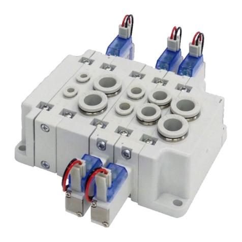
5-port manifold solenoid valve
* Valve width: 18 mm [0.709 in.]
Exhaust port
(Integrated mufer)
NEW OPTION!!
PAT.PEND.
The rst in the world!
Integrally molded, all-plastic body!
15
mm
[
0.591
in]
35.3 mm
[1.390 in]
Thin and lightweight!
Nearly 40%
smaller
Nearly 57% less
mass than the previous
180 series manifold
Quick tting for Inch tube added.
5/32 inch
●
1/4 inch
●
5/16 inch
●
3/8 inch
(End block only)
●
Easy assembly!
No. BK-P042-③

●❶
Handling Instructions and Precautions
Specifications Electrical Specifications
Mass
Rated voltage
Item 24 VDC
Applicable voltage range V 21.6 to 26.4 (24±10%)
Current (when rated voltage applied)
mA 23
Power consumption W 0.55
Allowable circuit leakage current
mA 1.0
Type of insulation B type
Insulation resistance Note MΩ 100 or over
Color of LED indicator Red
Surge protection (standard equipment)
Flywheel diode
Note: Value at 500 VDC Megger
Remark: Specication values are based on Koganei test standards.
Notes 1: The effective cross section values are calculated values, and are not measured values.
2: The valve when air pressure is 0.5 MPa [73 psi].
Item Model IBZR8-4E1 IBZR8-4E2
Number of positions 2 positions
Number of ports 5
Valve function Single solenoid Double solenoid
Medium Air
Operation system Internal pilot type
Flow rate
characteristics
Sonic conductance C dm
3
/(s·bar)
mm J42:0.8、J62:1.6、J82:2
in J5/32:0.8、J1/4:1.6、J5/16:2
Effective cross section area [Cv value] Note 1 mm2[Cv]
m m J 4 2:4〔 0 . 2 2 〕、J 6 2:8〔 0 . 4 4〕、J 8 2:10〔 0 . 5 6 〕
in
J
5
/
32
:
4
〔
0.22
〕、J
1/4
:
8
〔
0.44
〕、J5/16:10〔0.56〕
Connection port size
Supply port φ10 [0.394], outlet port φ4 [0.157], φ6 [0.236], φ8 [0.315]
Supply port 3/8、
outlet port 5/32、1/4、5/16
Lubrication Not required
Operating pressure range MPa [psi] 0.2 to 0.7 [29 to 102]
Proof pressure MPa [psi] 1.05 [152]
Operating temperature range (atmospheric and medium) ℃ [℉]
5 to 50 [41 to 122]
Response time Note 2 on/off time ms 15/30 or less 30 or less
Maximum operating frequency Hz 5
Shock resistance m/s2[G] 294.2 [30]
Mounting direction Unrestricted
Model Mass
IBZR8-4E1
J42: 59 [2.08], J62: 60 [2.12], J82: 63 [2.22]
J5/32
:5 9 [2.08]、
J1/4
:6 0 [2.12]、
J5/16
:6 3 [2.22]
IBZR8-4E2
J42: 75 [2.65], J62: 75 [2.65], J82: 78 [2.75]
J5/32
:7 5 [2.65]、
J1/4
:7 5 [2.65]、
J5/16
:7 8 [2.75]
IBZR8Z-E (end block) 81 [2.86]
IBZR8Z-E3/8 81 [2.86]
g [oz]
●24 VDC
Internal circuit
1. Do not apply megger between the pins.
2. Malfunctions, such as the solenoid valve not returning to normal, may occur
if there is a leakage current within the circuit. Always use it at less than the
allowable leakage current shown in the solenoid specifications. If circuit
conditions, etc. cause the leakage current to exceed the maximum
allowable leakage current, consult us.
3. For the double solenoid configuration, avoid energizing both solenoids
simultaneously.
NOTE
NOTE
NOTE
Solenoid with LED indicator and surge suppression
(-)
(+)
Lead wire
Red
Lead wire
Black
(Red)
Attaching and removing plug connector
Use fingers to insert the connector into the pin, push it in until the lever claw
latches onto the protruded section of the connector housing, and complete the
connection.
To remove the connector, squeeze the lever along with the connector, lift the
lever claw up from the protruded section of the connector housing, and pull it out.
Crimping of connecting lead wire and contact
To crimp lead wires into contacts, strip off 4 mm [0.16 in] of the insulation from
the end of the lead wire, insert it into the contact, and crimp it. Be sure at this
time to avoid catching the insulation on the exposed wire crimping section.
Attaching and removing contact and connector
Insert the contact with lead wire into a plug connector □hole until the
contact hook latches on and is secured to the plug connector. Confirm
that the lead wire cannot be easily pulled out.
To remove it, insert a tool with a fine tip (such as a small screwdriver)
into the rectangular hole on the side of the plug connector to push up
on the hook, and then pull out the lead wire.
1. Do not pull hard on the lead wire. It could result in defective contacts,
breaking wires, etc.
2. If the pin is bent, use a small screwdriver, etc. to gently straighten out the
pin, and then complete the connection to the plug connector.
1.
Do not pull hard on the lead wire.
2.
Always use a dedicated tool for crimping of connecting lead wire and contact.
Contact: Model 702062-2M
Manufactured by Sumiko Tech, Inc.
Crimping tool: Model F1-702062
Manufactured by Sumiko Tech, Inc.
Protrusion
Pin
Housing
Lever
Connector
Indication of
polarity(DC)
Contact
Connector assembly
KSB0352Z
Hook Exposed wire
crimping section
Insulation crimp tab
Insulation (Maximum outer diameter: φ1.7 [0.067])
Lead wire
Equivalent to AWG#22〜#28
Exposed wire 4 mm [0.16 in]
Contact
KSB0353Z
To operate the manual override, press it all the way down.
For the single solenoid, the valve works the same as when in the energized
state as long as the manual override is pushed down, and returns to the rest
position upon release.
For the double solenoid, pressing the manual override on the 14 (SA) side
switches the 14 (SA) to the energized state, and the unit remains in that state
even after the manual override is released. To return it to the rest position,
operate the manual override on the 12 (SB) side. This is the same for the
solenoid 12 (SB).
PUSH
NOTE
1. The iB-ZERO series uses pilot type solenoid valves, so if you do not
supply air to the 1 (P) port, the main valve will not change, even if
you operate the manual override.
2. Do not attempt to operate the manual override with a pin or other
object having an extremely fine tip. It could result in damage to the
manual override.
Manual override
mm
in
mm
in
mm
in
Identification of quick fitting size
Tube size unit Release ring color
mm size Ivory
in size Milk white

●❷
Order codes
●Manifold
● End block (left-right set)
IBZR8Z -
● Single valve unit (The single valve unit cannot be used alone.)
■ Valve specifications
■ Manifold format
Manifold is
complete.
■
Specifications for fittings of pipe ports
■ Wiring specification
■
Specifications for fittings of pipe ports
-PL1
-PL1
-PL
-PL
-PLN
-PLN
Note 1: Note1: The maximum number of valves is 20 stations. When the DIN rail mounting bracket is selected, the maximum is 16 stations.
2: After doing connections, before supplying air to the manifold, be sure to check that the connections that were made between each valve and end block are secure.
3: Please separately prepare the DIN rail. When -NS is selected for the maniflod format, the DIN rail mounting brackets will be attached parts.
4: Valve positions are counted from the left side of the manifold.
5: Common connector assemblies are available for common wiring connections. For details, see page ❸.
6:
When connecting common wires between double solenoid valves on the 12 (SB) side, connections are possible between double solenoid valves if 1single solenoid valve is mounted between them, or even if
1 intermediate piping block is mounted between them. However, connections cannot be done if there are two or more, due to the relative length of the branch wires for common connections.
7: For questions regarding support for 5-V, 6-V, and 12-V DC products, contact our sales office.
8: (mm) fitting and (in.) fitting valves cannot be mixed in the same manifold.
Remarks: The gasket is installed in the valve body. Two mounting screws (bracket attached) are provided with the valve body.
Note: For questions regarding support for 5-V, 6-V, and 12-V DC products, contact our sales office.
The manifold can be easily made by assembling the end block and the valve.
See page ❹ for details
IBZR8
stn.1
·
·
·
stn.□
Note 4
N
NS
Note 2
IBZR8M
-4E1
-4E2
-4E1
-4E2
-PL
-PL1
-PLN
24 VDC
Note
24 VDC
Note 7
Model
IBZR8
ModelModel
Number of valves
Manifold format
Piping block
Manifold model Model of mounted valve
Valve specifications
Specifications for fittings of pipe ports
Wiring specification
Specifications for fittings of pipe ports
Wiring specification
Voltage
Voltage
Right side
Left side
-4E1: 5-port, 2-position single solenoid
-4E2: 5-port, 2-position double solenoid
-4E1: 5-port, 2-position single solenoid
-4E2: 5-port, 2-position double solenoid
N: Finished product has each valve
connected
(fixed with mounting screw (bracket attached))
NS: Semi-finished product before
each valve is connectedNote 1
*
Mounting screws (bracket attached)
must be used to connect and fix each
valve before use.
(mounting screw (bracket attached) provided)
-J42: quick fitting for φ4 [0.157] tubes
-J62: quick fitting for φ6 [0.236] tubes
-J82: quick fitting for φ8 [0.315] tubes
+
Each type of valve
End block
Single solenoid Double solenoid
4 (A)
2 (B)
12 (SB)
14 (SA)
4 (A)
2 (B)
14 (SA)
3 (R2)
5 (R1)
1 (P)
3 (R2)
5 (R1)
1 (P)
L type plug connector
Lead wire 300 mm [11.8 in]
L type plug connector
Lead wire 300 mm [11.8 in]
L type plug connector
Lead wire 1000 mm [39 in]
L type plug connector
Lead wire 1000 mm [39 in]
L type plug connector
No connector
L type plug connector
No connector
Mounting screw
(bracket attached)
-PJ(If an intermediate piping block is mounted on the specified station)
-PL3/8
Note 8
-J42:
quick fitting for φ4 [0.157] tubes
-J62:
quick fitting for φ6 [0.236] tubes
-J82:
quick fitting for φ8 [0.315] tubes
-J5/32:
quick fitting for 5/32 in. tubes
-J1/4 :
quick fitting for 1/4 in. tubes
-J5/16:
quick fitting for 5/16 in. tubes
-J5/32
-J1/4
-J5/16
-J42
-J62
-J82
E:quick fitting for φ10 [0.394] tube
E3/8:quick fitting for 3/8 in. tube
-J5/32:quick fitting for 5/32 in. tubes
-J1/4: quick fitting for 1/4 in. tubes
-J5/16: quick fitting for 5/16 in. tubes
-CPL
Pre-wired positive
common terminal
Note6
Lead wire 300mm
■Mounting
Blank: Direct mounting
-DN: With DIN rail mounting bracket Note 1,Note 3
■Piping block
Blank: Quick fiting for φ10mm tube
-J3/8: Quick fiting for 3/8 inch tube
Blank
-DN
Note 1,Note 3
Mounting
Blank
-J3/8
Note 8
Stations
-J5/32
-J1/4
-J5/16
-J42
-J62
-J82
Note 8
Note 8
Note 8
Note 8
Note 8
Note 8
-PLN
-CPL
-PL
-PL1
Note 5
Note 6
1
・
・
・
20
(16)
Note 1

● Additional parts (available separately)
DIN rail mounting bracket Gasket
Set of brackets and
mounting screws
(Units: 2 pcs)
(4 mounting screws
included)
(With 1 gasket and 2 connecting
brackets attached)
(Units: 1)
Intermediate piping block
IBZR
8
Z-GS IBZR
8
Z-KN
●❸
EAZ -
Connector-related
Connector specification
P :
Connector, lead wire length 300 mm [11.8 in]
P1 :
Connector, lead wire length 1000 mm [39 in]
P3 :
Connector, lead wire length 3000 mm [118 in]
PN :
Connector, without lead wire (contacts included)
EAZ -
Common connector assembly
Lead wire assembly (order made) with completed common connections
Application example
Connector specification
PA :
Positive common A type, connector, lead wire length 300 mm [11.8 in]
PA1 : Positive common A type, connector, lead wire length 1000 mm [39 in]
PA3 :
Positive common A type, connector, lead wire length 3000 mm [118 in]
PB :
Positive common B type, connector, lead wire length 300 mm [11.8 in]
PB1 :
Positive common B type, connector, lead wire length 1000 mm [39 in]
PB3 :
Positive common B type, connector, lead wire length 3000 mm [118 in]
PC :
Positive common C type, connector, lead wire length 300 mm [11.8 in]
PC1 :
Positive common C type, connector, lead wire length 1000 mm [39 in]
PC3 :
Positive common C type, connector, lead wire length 3000 mm [118 in]
CPN :
Positive common, connector, without lead wire (short bar and contacts included)
Red (+) (For common wiring)
Black (
−
)
Red (
+
)
Black (
−
)
Red (
+
)
Red (+) (For common wiring)
Black (
−
)
*Lead wire length Blank: 300 mm [11.8 in]
1: 1000 mm [39 in]
3: 3000 mm [118 in]
A type B type B type C typeB type B type
Connection example
A type: EAZ-PA□*
B type: EAZ-PB□*
C type: EAZ-PC□*
Branch wire
Order codes
For the EAZ-1W-6P□
Using lead wire assemblies with completed common connections reduces wiring.
Number of units wired together
2: 2 connections
20: 20 connections
Lead wire assembly with completed common connections
〜
Lead wire length
Blank 300 mm [11.8 in]
1 1000 mm [39 in]
33000 mm [118 in]
Order codes
EAZ-1W - P
(+)
Red
(-)
Black
(-)
Black
(-)
Black
(-)
Black
(-)
Black
(+)
Red
Common wires
(-)
Black
Common wires
Branch wire (red)
NOTE
NOTE
1. Due to the relative length of the branch
wires for common wire connections,
connections cannot be done if two or more
intermediate piping blocks are mounted
between valves.
2. When connecting common wires between
double solenoid valves on the 12 (SB) side,
connections are possible between double
solenoid valves if 1 single solenoid valve is
mounted between them, or even if 1
intermediate piping block is mounted
between them. However, connections
cannot be done if there are two or more,
due to the relative length of the branch
wires for common connections.
1. Due to the relative length of the branch
wires for common wire connections,
connections cannot be done if two or
more intermediate piping blocks are
mounted between valves.
2. When connecting common wires
between double solenoid valves on
the 12 (SB) side, connections are
possible between double solenoid
valves if 1 single solenoid valve is
mounted between them, or even if 1
intermediate piping block is mounted
between them. However, connections
cannot be done if there are two or
more, due to the relative length of the
branch wires for common connections.
Red (+) (For common wiring)
Black (
−
)
Red (
+
)
Black (
−
)
Red (
+
)
Red (+) (For common wiring)
Black (
−
)
*Lead wire length Blank: 300 mm [11.8 in]
1: 1000 mm [39 in]
3: 3000 mm [118 in]
A type B type B type C typeB type B type
Connection example
A type: EAZ-PA□*
B type: EAZ-PB□*
C type: EAZ-PC□*
Branch wire
DIN rail
(Unit: 1 pcs)
DIN-□
DIN -
125:125mm
150:150mm
175:175mm
200:200mm
225:225mm
250:250mm
275:275mm
300:300mm
325:325mm
350:350mm
375:375mm
400:400mm
425:425mm
450:450mm
475:475mm
500:500mm
Length of DIN rail
End block (left-right set)
(With 1 gasket and 2 connecting
brackets attached)
IBZR8Z-
E:quick fitting for φ10 [0.394] tube
E3/8:quick fitting for 3/8 in. tube
IBZR8Z-
PJ:quick fitting for φ10 [0.394] tube
PJ3/8:quick fitting for 3/8 in. tube
IBZR
8
Z-DN
NOTE
When using DIN rail
mounting brackets, the
maximum number of
valves is 16 stations.

How to assemble and replace valves
①
Remove the mounting screws (bracket attached) from the four places (when adding valves, the two places on the top and bottom of
where you are adding the valve) on the top and bottom of the valve to replace.
Refer to ③and ④when the customer is the one purchasing the end block and valves and assembling the manifold.
②
The valve and end block can be removed by opening them diagonally and pulling up.
③
Assemble while diagonally aligning the positions of the indents and protrusions of the new valve.
④
After attaching, x it with a mounting screws. (Recommended tightening torque: 0.49 N•m [0.36 ft•lbf])
Assemble or replace the valves while the manifold body is not xed.
Mounting screw
(bracket attached)
[Caution]
● Always turn off the power and the air supplies before starting work. Also, be sure to proceed after checking that all air from inside the manifold is
vented.
● The maximum number of units that can be connected in a series is 20, including intermediate piping blocks.
● Be careful that the gasket is not pinched or does not fall out.
● Before supplying air to the manifold, be sure to check that the connections that were made between each valve and end block are secure.
● We recommend adding intermediate piping blocks 「IBZR8Z-PJ(-PJ3/8)」 if needed, when there is a large number of valves or a large number
of valves simultaneously supplying air to the secondary side. Also, be careful of actuator malfunctions caused by the exhaust pressure.
Furthermore, both intermediate piping blocks 「IBZR8Z-PJ(-PJ3/8)」 and valves can be added using the same procedure.
● The exhaust port is an integrated muffler type. Before use, confirm that there is no exhaust noise or increase in pressure in the control panel when it
is sealed.
● Air leakage from valves is not zero. For questions regarding the allowable amount of leakage, contact our sales office.
[Warranty Period]
● The warranty period for this product is 12 months from the date of delivery. However, failure, loss of performance, or loss of function due to normal
degradation is outside the scope of warranty, even if it is within the warranty period.
Mounting
screw
(bracket
attached)
Air supply port
Air supply port
Exhaust port
(Integrated muffler)
Same on
other side
Right side
Gasket-side
Gasket
End block
Left side
Groove
Protrusion
Intermediate piping block
IBZR8Z-PJ
(Sold separately)
Open diagonally
Pull up
Close
Align the indents
and protrusions
●❹
Before use, be sure to read the "Safety Precautions" and "General Precautions" in the general catalog.

Dimensions mm [in]
Number of units
LNote PNote
55 [2.165]
70 [2.756]
85 [3.346]
100 [3.9]
115 [4.5]
130 [5.1]
145 [5.7]
160 [6.3]
175 [6.9]
190 [7.5]
205 [8.1]
220 [8.7]
235 [9.3]
250 [9.8]
265 [10.4]
280 [11]
295 [11.6]
310 [12.2]
325 [12.8]
340 [13.4]
46 [1.811]
61 [2.402]
76 [2.992]
91 [3.583]
106 [4.2]
121 [4.8]
136 [5.4]
151 [5.9]
166 [6.5]
181 [7.1]
196 [7.7]
211 [8.3]
226 [8.9]
241 [9.5]
256 [10.1]
271 [10.7]
286 [11.3]
301 [11.9]
316 [12.4]
331 [13]
Unit dimensions
1
2
3
4
5
6
7
8
9
10
11
12
13
14
15
16
17
18
19
20
10.8 [0.425]
30 [1.181]
(300 [11.8])
LED indicator
35.8 [1.409]
Exhaust port
(Integrated muffler)
stn. 1 stn. 2 stn. 3 stn. 4
15 [0.591]
4 (A) port
2 (B) port
Fitting
(φ4 [0.157])
Fitting
(φ6 [0.236])
Mounting screw
Fitting (φ8 [0.315])
1 (P) port
4-φ4.2 [0.165] (Oval hole)
(Mounting hole)
Fitting (φ10 [0.394])
15 [0.591]
22.5
[0.886]
15 [0.591]
17.5
[0.689]
Manual override
(pitch)
4.5 [0.177]
4.5 [0.177] P
L
25 [0.984]
(5.3 [0.209])
6 [0.236]
-J42: (2.6 [0.102])
-J62: (3.0 [0.118])
-J82: (4.7 [0.185])
35.3 [1.39]
72.3 [2.846]
62 [2.441]
102 [4.016]
15 [0.591]
28.3 [1.114]
5.2 [0.205]
77.2 [3.039]
131.6 [5.18]
4.9 [0.193]
IBZR8-4E1-J□-PL
IBZR8M□N
IBZR8Z-PJ
IBZR8-4E2-J□-PL
5-port single solenoid 5-port double solenoid
■ Single valve unit (With quick fittings for mm tubes)
■ Manifold
■ Intermediate piping block (single unit)
[Mounting example]
IBZRM4N
stn.1 IBZR8-4E1-J42-PL 24 VDC
stn.2 IBZR8-4E1-J62-PL 24 VDC
stn.3 IBZR8-4E1-J82-PL 24 VDC
stn.4 IBZR8-4E2-J82-PL 24 VDC
20 [0.787]
Exhaust port
Exhaust port (Integrated muffler)
(Integrated muffler)
(Same position on other side)
72.3 [2.846]
35 [1.378]
(5.3 [0.209])
2 mounting screws provided
Note:If intermediate piping
blocks are mounted, add
20 mm [0.787 in] for each
of the intermediate piping
blocks in L and P.
10.5
[0.413]
2 mounting screws provided
35 [1.378]
77.2 [3.039]
15
[0.591]
28.3
[1.114]
102 [4.016]
30 [1.181]
(300 [11.8])
15 [0.591]
10 [0.394]
Manual override
4 (A) port
2 (B) port
Fitting
-J42:φ4 [0.157]
-J62:φ6 [0.236]
-J82:φ8 [0.315]
-J42: (2.6 [0.102])
-J62: (3 [0.118])
-J82: (4.7 [0.185])
131.6 [5.18]
82 [3.228]
10.5
[0.413]
35 [1.378]
15
[0.591]
10 [0.394]
15 [0.591]
30 [1.181]
-J42:φ4 [0.157]
-J62:φ6 [0.236]
-J82:φ8 [0.315]
Fitting
Manual override
4 (A) port
2 (B) port
-J42: (2.6 [0.102])
-J62: (3 [0.118])
-J82: (4.7 [0.185])
(300 [11.8])
2 mounting screws provided
If intermediate piping block is mounted
(Model: IBZR8-PJ)
Exhaust port (Integrated muffler)
1 (P) port
Fitting (φ10 [0.394])
Intermediate piping block
20 [0.787]
Exhaust port (Integrated muffler)
(Same position on other side)
●❺

Number of units
LNote Q Note
●❻
Dimensions mm [in]
IBZR8M□N-DN (With quick fitting for mm tubes)
■Manifold (With DIN rail mounting bracket)
55[2.165]
70[2.756]
85[3.347]
100[3.347]
115[3.937]
130[5.118]
145[5.709]
160[6.299]
175[6.890]
190[7.480]
205[8.071]
220[8.661]
235[9.252]
250[9.843]
265[10.433]
280[11.023]
79[3.110]
94[3.701]
109[4.291]
124[4.882]
139[5.472]
154[6.063]
169[6.654]
184[7.244]
199[7.835]
214[8.425]
229[9.016]
244[9.606]
259[10.197]
274[10.787]
289[11.378]
304[11.969]
Unit dimensions
1
2
3
4
5
6
7
8
9
10
11
12
13
14
15
16
[Mounting example]
IBZR8M4N-DN
stn.1 IBZR8-4E1-J42-PL DC24V
stn.2 IBZR8-4E1-J62-PL DC24V
stn.3 IBZR8-4E1-J82-PL DC24V
stn.4 IBZR8-4E2-J82-PL DC24V
Note:If intermediate piping blocks
are mounted, add 20 mm
[0.787 in] for each of the
intermediate piping blocks in
L and P.
DIN rail mounting brackets
As shown in below images, rst make sure that the DIN rail mounting bracket is mounted on both sides of the manifold. Then
securely connect the hooks of both sides to the DIN rail from above, and x the position with DIN rail mounting screws.
When the DIN rail mounting bracket is selected, the maximum is number of valves is 16 stations.
DIN rail mounting screw
Fix with DIN rail mounting screw
Tightening torque 0.74 N [0.55 ft
・
lbf]
(Same for other side)
DIN rail mounting
bracket
Main unit mounting screw
Tightening torque 0.74 N
[0.55 ft
・
lbf]
Hooks (both sides)
47 [1.850]
12.7 [0.500]
(7.5)
[0.295]
DIN rail mounting bracket
(Attached when NS is selected)
12[0.472]
Q
L
Mountingscrew
Fitting
(φ6 [0.236])
Fitting
(φ4 4[0.157])
2(B)Port
Fitting(φ10 [0.394])
LEDindicator
(Pitch)
Manualoverride
17.5
[0.689]
15 [0.591]
22.5
[0.886]
15
[0.591]
1(P)Port
35.8[1.409]
Fitting(φ8 [0.315])
4.9 [0.193]
131.6[5.18]
77.2 [3.039]
4(A)Port
28.3 [1.114]
15 [0.591]
102 [4.016]
72.3 [2.846]
15 [0.591]
35.3
[1.390]
30
[1.181]
10.8
[0.425]
(300)
[11.8]
s t n .1 s t n .2 s t n .3 s t n .4
25
[0.984]
-J42: (2.6 [0.102])
-J62: (3.0 [0.118])
-J82: (4.7 [0.185])
(5.3)
[0.209]
Exhaust port
(Integrated muffler)
DIN rail mounting hole dimension
(12.5)[0.492]
20.5
35[1.378]
5.5[0.217]
25[0.984]
[0.807]
DIN-□
■DIN rail
NOTE

❼
Dimensions mm [in]
Unit dimensions
IBZR8-4E1-J□-PL
IBZR8M□N-J3/8
IBZR8Z-PJ3/8(With quick fittings for Inch tubes)
IBZR8-4E2-J□-PL
5-port single solenoid 5-port double solenoid
■ Single valve unit (With quick fittings for Inch tubes)
■ Manifold(With quick fittings for Inch tubes)
■ Intermediate piping block (single unit)
[Mounting example]
IBZR8M4N-J3/8
stn.1 IBZR8-4E1-J5/32-PL DC24V
stn.2 IBZR8-4E1-J1/4-PL DC24V
stn.3 IBZR8-4E1-J5/16-PL DC24V
stn.4 IBZR8-4E2-J5/16-PL DC24V
Note:If intermediate piping blocks are mount-
ed, add 20 mm [0.787 in] for each of
the intermediate piping blocks in L and
P.
Number of units
LNote PNote
1 55 [2.165] 46 [1.811]
2 70 [2.756] 61 [2.402]
3 85 [3.346] 76 [2.992]
4 100 [3.937] 91 [3.583]
5 115 [4.528] 106 [4.173]
6 130 [5.118] 121 [4.764]
7 145 [5.709] 136 [5.354]
8 160 [6.299] 151 [5.945]
9 175 [6.890] 166 [6.535]
10 190 [7.480] 181 [7.126]
11 205 [8.071] 196 [7.717]
12 220 [8.661] 211 [8.307]
13 235 [9.252] 226 [8.898]
14 250 [9.843] 241 [9.488]
15 265 [10.433] 256 [10.079]
16 280 [11.024] 271 [10.669]
17 295 [11.614] 286 [11.260]
18 310 [12.205] 301 [11.850]
19 325 [12.795] 316 [12.441]
20 340 [13.386] 331 [13.031]
(Model:IBZR8-PJ3/8)
1(P)port
20[0.787]
If intermediate piping block is mounted
Exhaust port (Integrated muffler)
Intermediate piping block
Fitting (3/8)
Exhaust port (Integrated muffler)
(Same position on other side)
10.8 [0.425]
30 [1.181]
(300) [11.8]
35.8 [1.409]
stn. 1 stn. 2 stn. 3 stn. 4
15 [0.591]
4 (A) Port
2 (B) Port
Fitting
(5/32)
Fitting
(1/4)
Mounting screw
1 (P) Port
4-φ4.2 [0.165] (Oval hole)
(Mounting hole)
Fitting(3/8)
15 [0.591]
22.5
[0.886]
15 [0.591]
17.5
[0.689]
(
Pitch
)
4.5 [0.177]
4.5 [0.177] P
L
25 [0.984]
(5.3) [0.209]
6 [0.236]
-J5/32: (2.6) [0.102]
-J1/4: (3.4) [0.134]
-J5/16: (4.7) [0.185]
35.3 [1.39]
72.3 [2.846]
62 [2.441]
102 [4.016]
15 [0.591]
28.3 [1.114]
5.2 [0.205]
77.2 [3.039]
131.6 [5.18]
4.9 [0.193]
Fitting(5/16)
LED indicator
Manual override
Exhaust port
(Integrated muffler)
10.5
[0.413]
35 [1.378]
77.2 [3.039]
15
[0.591]
28.3
[1.114]
102 [4.016]
30 [1.181]
(300) [11.8]
15 [0.591]
10 [0.394]
4 (A) Port
2 (B) Port
-J5/32: 5/32
-J1/4: 1/4
-J5/16: 5/16
-J5/32(2.6)[0.102]
-J1/4(3.4)[0.134]
-J5/16(4.7)[0.185]
2mountingscrewsprovided
Fitting
Manualoverride
131.6 [5.18]
82 [3.228]
10.5
[0.413]
35 [1.378]
15
[0.591]
10 [0.394]
15 [0.591]
30 [1.181]
-J5/32: 5/32
-J1/4: 1/4
-J5/16: 5/16
4 (A) Port
2 (B) Port
-J5/32: (2.6) [0.102]
-J1/4: (3 .4) [0.134]
-J5/16: (4.7) [0.185]
(300) [11.8]
2mountingscrewsprovided
Fitting
Manualoverride
20 [0.787]
Exhaust port
Exhaust port (Integrated muffler)
(Integrated muffler)
(Same position on other side)
72.3 [2.846]
35 [1.378]
(5.3 [0.209])
2 mounting screws provided

●❽
Dimensions mm [in]
Unit dimensions
IBZR8M□N-DN-J3/8(With quick fittings for Inch tubes)
■Manifold (With DIN rail mounting bracket)
[Mounting example]
IBZR8M4N-DN-J3/8
stn.1 IBZR8-4E1-J5/32-PL DC24V
stn.2 IBZR8-4E1-J1/4-PL DC24V
stn.3 IBZR8-4E1-J5/16-PL DC24V
stn.4 IBZR8-4E2-J5/16-PL DC24V
Note:If intermediate piping blocks are mount-
ed, add 20 mm [0.787 in] for each of
the intermediate piping blocks in L and
P.
(7.5)
[0.295]
DIN rail mounting bracket
(Attached when NS is selected)
47[1.85]
12.7[0.5]
12
[0.472]
Q
L
2(B)Port
Fitting(3/8)
17.5
[0.689]
15[0.591]
22.5
[0.886]
15
[0.591]
1(P)Port
35.8[1.409]
Fitting(5/16)
4.9[0.193]
131.6[5.18]
77.2[3.039]
4(A)Port
28.3
[1.114]
15
[0.591]
102[4.016]
72.3[2.246]
15[0.591]
35.3[1.39]
30[1.181] 10.8[0.425]
(300)[11.811]
s t n .1 s t n .2 s t n .3 s t n .4
-J5/32:(2.6)[0.102]
-J1/4:(3.4)[0.134]
-J5/16:(4.7)[0.185]
25
(5.3)
Exhaust port
(Integrated muffler)
Mounting screw
Fitting
(5/32) Fitting(1/4)
Manual override
(
Pitch
)
LED indicator
Number of units
LNote QNote
155 [2.165] 77 [3.031]
270 [2.756] 94 [3.701]
385 [3.346] 109 [4.291]
4100 [3.937] 124 [4.882]
5115 [4.528] 139 [5.472]
6130 [5.118] 154 [6.063]
7145 [5.709] 169 [6.654]
8160 [6.299] 184 [7.244]
9175 [6.890] 199 [7.835]
10 190 [7.480] 214 [8.425]
11 205 [8.071] 229 [9.016]
12 220 [8.661] 244 [9.606]
13 235 [9.252] 259 [10.197]
14 250 [9.843] 274 [10.787]
15 265 [10.433] 289 [11.378]
16 280 [11.024] 304 [11.969]
DIN-□
■DIN rail
DIN rail mounting hole dimension
(12.5)[0.492]
20.5
35[1.378]
5.5[0.217]
25[0.984]
[0.807]

MEMO
❾

MEMO
●❿

Limited Warranty
KOGANEI CORP. warrants its products to be free from defects
in material and workmanship subject to the following provisions.
The warranty period is 180 days from the date
of delivery.
If a defect in material or workmanship is found
during the warranty period, KOGANEI CORP.
will replace any part proved defective under
normal use free of charge and will provide the
service necessary to replace such a part.
This warranty is in lieu of all other warranties,
expressed or implied, and is limited to the
original cost of the product and shall not
include any transportation fee, the cost of
installation or any liability for direct, indirect
or consequential damage or delay resulting
from the defects.
KOGANEI CORP. shall in no way be liable or responsible for
injuries or damage to persons or property arising out of the
use or operation of the manufacturer’s product.
This warranty shall be void if the engineered safety devices
are removed, made inoperative or not periodically checked for
proper functioning.
Any operation beyond the rated capacity, any improper use or
application, or any improper installation of the product, or any
substitution upon it with parts not furnished or approved by
KOGANEI CORP., shall void this warranty.
This warranty covers only such items supplied by KOGANEI
CORP. The products of other manufacturers are covered only by
such warranties made by those original manufacturers, even
though such items may have been included as the components.
The specifications are subject to change without notice.
Warranty Period
Koganei
Responsibility
Limitations •
•
•
•
•
URL http://www.koganei.co.jp
E-mail: [email protected]
4/’19 KG
©KOGANEI CORP. PRINTED IN JAPAN
OVERSEAS DEPARTMENT
3-11-28, Midori-cho, Koganei City, Tokyo 184-8533, Japan
Tel: 81-42-383-7271 Fax: 81-42-383-7276
KOGANEI INTERNATIONAL AMERICA, INC.
39300 Civic Center Dr., Suite 280, Fremont, CA 94538, U.S.A.
Tel : 1-510-744-1626 Fax : 1-510-744-1676
SHANGHAI KOGANEI INTERNATIONAL TRADING CORPORATION
Room 2606-2607, Tongda Venture Building No.1, Lane 600, Tianshan Road,
Shanghai, 200051, China
Tel: 86-21-6145-7313 Fax: 86-21-6145-7323
TAIWAN KOGANEI TRADING CO., LTD.
Rm. 2, 13F., No88, Sec. 2, Zhongxiao E. Rd., Zhongzheng Dist., Taipei City 100,
Taiwan (ROC)
Tel: 886-2-2393-2717 Fax: 886-2-2393-2719
KOGANEI KOREA CO., LTD.
6F-601, Tower Bldg., 1005, Yeongdeo-dong, Giheung-gu, Yongin-si, Gyeonggi-do,
446-908, Korea
Tel: 82-31-246-0414 Fax: 82-31-246-0415
KOGANEI (THAILAND) CO., LTD.
3300/90, Tower B, Elephant Tower,16th Fl., Phaholyothin Road, Chomphon,
Chatuchak, Bangkok 10900, Thailand
Tel: 66-2-937-4250 Fax: 66-2-937-4254
KOGANEI ASIA PTE. LTD.
69 Ubi Road 1, #05-18 Oxley Bizhub, Singapore 408731
Tel: 65-6293-4512 Fax: 65-6293-4513
URL http://www.koganei.co.jp
E-mail: [email protected]
This manual suits for next models
2
Table of contents
Other Koganei Control Unit manuals

Koganei
Koganei CVR01 Series User manual

Koganei
Koganei 180 Series User manual

Koganei
Koganei 010 SERIES User manual

Koganei
Koganei KFPV050 Series User manual

Koganei
Koganei ib-ZERO User manual

Koganei
Koganei KFPV050 Series User manual

Koganei
Koganei F Series User manual

Koganei
Koganei FVN01-01 Series User manual