Industrial Scientific Ventis Pro Series User manual

Product
Manual
The Essential Guide for
Safety Teams and
Instrument Operators
Edition 3
March 23, 2016
Part Number: 17156830-1

Industrial Scientific Corporation, Pittsburgh, PA USA
Industrial Scientific Co., Ltd. Shanghai, China
© 2015, 2016 Industrial Scientific Corporation
All rights reserved. Published 2016.
Revision 1
www.indsci.com/ventispro

Contents
General Information .......................................................................................................................................................................... 1
Certifications ................................................................................................................................................................................. 1
Warnings and Cautionary Statements .......................................................................................................................................... 2
Recommended Practices.............................................................................................................................................................. 4
Instrument Maintenance ........................................................................................................................................................... 4
First Use.................................................................................................................................................................................... 5
Wearing the Instrument............................................................................................................................................................. 5
Remote Sampling ..................................................................................................................................................................... 6
Cold-weather Operation............................................................................................................................................................ 6
Product Information........................................................................................................................................................................... 7
Overview ....................................................................................................................................................................................... 7
Key Features................................................................................................................................................................................. 7
Compatibility ................................................................................................................................................................................. 8
Sensors..................................................................................................................................................................................... 8
Batteries.................................................................................................................................................................................. 10
Specifications.............................................................................................................................................................................. 11
Instrument ............................................................................................................................................................................... 11
Battery Specifications ............................................................................................................................................................. 12
Sensor Specifications ............................................................................................................................................................. 12
Getting Started................................................................................................................................................................................ 21
Unpacking the Instrument ........................................................................................................................................................... 21
Hardware Overview .................................................................................................................................................................... 22
Display Overview ........................................................................................................................................................................ 24
Power On .................................................................................................................................................................................... 30
Power Off .................................................................................................................................................................................... 33
Settings........................................................................................................................................................................................... 35
Guidelines ................................................................................................................................................................................... 35
Accessing and Protecting Settings ............................................................................................................................................. 35
Settings Menus ........................................................................................................................................................................... 36
Examples for Working in Settings ............................................................................................................................................... 36
Reviewing and Editing Settings .................................................................................................................................................. 38
Maintenance menu ................................................................................................................................................................. 39
Start-up menu ......................................................................................................................................................................... 41
Operation menu ...................................................................................................................................................................... 42
Alarm menu............................................................................................................................................................................. 43
Sensor menu........................................................................................................................................................................... 45
Admin Menu............................................................................................................................................................................ 46
Operation ........................................................................................................................................................................................ 49

The Instrument Buttons............................................................................................................................................................... 49
The Instrument Display ............................................................................................................................................................... 50
Operating the Instrument ............................................................................................................................................................ 50
Information .............................................................................................................................................................................. 50
Utilities .................................................................................................................................................................................... 50
Wearing the Instrument............................................................................................................................................................... 52
Alarms and Warnings At-a-glance .............................................................................................................................................. 52
Alarms..................................................................................................................................................................................... 52
Warnings................................................................................................................................................................................. 53
User-site Assignments ................................................................................................................................................................ 54
Alarms, Warnings, and Other Notifications ..................................................................................................................................... 55
Overview ..................................................................................................................................................................................... 55
Alarms......................................................................................................................................................................................... 55
Warnings..................................................................................................................................................................................... 58
Indicators .................................................................................................................................................................................... 59
Failures and Errors ..................................................................................................................................................................... 59
Maintenance ................................................................................................................................................................................... 61
Guidelines ................................................................................................................................................................................... 61
Process At-a-glance.................................................................................................................................................................... 61
Supplies and Preparation............................................................................................................................................................ 62
Instruction ................................................................................................................................................................................... 63
Service and Warranty ..................................................................................................................................................................... 67
Service ........................................................................................................................................................................................ 67
Guidelines ............................................................................................................................................................................... 67
Supplies .................................................................................................................................................................................. 67
Instruction ............................................................................................................................................................................... 68
Warranty ..................................................................................................................................................................................... 77
Limitation of Liability................................................................................................................................................................ 77
Assignments ................................................................................................................................................................................... 79
Introduction ................................................................................................................................................................................. 79
iAssign Overview ........................................................................................................................................................................ 79
Procedures.................................................................................................................................................................................. 81
Appendix......................................................................................................................................................................................... 85
Supplemental Information about Gases and Sensors ................................................................................................................ 85
Toxic Gases ............................................................................................................................................................................ 85
Combustible Gases................................................................................................................................................................. 86
Contact Information....................................................................................................................................................... Back cover90

Tables and Figures
Table 1.1 Hazardous area certifications ........................................................................................................................................... 1
Table 1.2 Wireless certifications ....................................................................................................................................................... 2
Table 1.3 Warnings and cautionary statements................................................................................................................................ 2
Table 1.4 Recommended frequencies for instrument maintenance ................................................................................................. 5
Figure 2.1.A Sensor compatibility and installation locations for the Ventis Pro4 .............................................................................. 9
Figure 2.1.B Sensor compatibility and installation locations for the Ventis Pro5 .............................................................................. 9
Table 2.1 Sensor compatibility and installation locations................................................................................................................ 10
Table 2.2 Battery compatibility........................................................................................................................................................ 10
Table 2.3 Instrument and pump specifications ............................................................................................................................... 11
Table 2.4 Battery specifications...................................................................................................................................................... 12
Table 2.5 Sensor specifications ...................................................................................................................................................... 13
Table 3.1 Package contents ........................................................................................................................................................... 21
Figure 3.1.A Hardware overview diffusion instrument .................................................................................................................... 22
Figure 3.1.B Hardware overview aspirated instrument ................................................................................................................... 23
Figure 3.2.A Reading the display during operation......................................................................................................................... 25
Figure 3.2.B Reading the display during an event (warning or alarm)............................................................................................ 26
Figure 3.2.C Reading the display during maintenance ................................................................................................................... 27
Figure 3.2.D Reading the display while working in settings............................................................................................................ 28
Figure 3.3 Power on........................................................................................................................................................................ 32
Figure 3.4 Power off........................................................................................................................................................................ 33
Table 4.1 Settings menus ............................................................................................................................................................... 36
Figure 4.1.A Example for editing a single-item setting.................................................................................................................... 37
Figure 4.1.B Example for editing a multi-item setting ..................................................................................................................... 38
Figure 4.2.A Navigating and using maintenance options................................................................................................................ 40
Figure 4.2.B Navigating and editing start-up settings .................................................................................................................... 41
Figure 4.2.C Navigating and editing operation settings ................................................................................................................. 43
Figure 4.2.D Navigating and editing alarm settings ....................................................................................................................... 44
Figure 4.2.E Navigating and editing sensor settings...................................................................................................................... 45
Figure 4.2.F Navigating and editing admin settings....................................................................................................................... 47
Figure 5.1 Using the buttons during operation................................................................................................................................ 49
Figure 5.2 Home ............................................................................................................................................................................. 50
Figure 5.3 Operation instruction...................................................................................................................................................... 51
Figure 5.4 Using iAssign tags ......................................................................................................................................................... 54
Table 6.1 Alarm events (list) ........................................................................................................................................................... 56
Figure 6.1 Alarm events (display screens)...................................................................................................................................... 57
Table 6.2 Warning events (list) ....................................................................................................................................................... 58
Figure 6.2 Warning events (display screens).................................................................................................................................. 59
Table 6.3 Failures and errors.......................................................................................................................................................... 59
Table 6.4 Critical errors................................................................................................................................................................... 60

Figure 7.1 Maintenance supplies and preparation.......................................................................................................................... 62
Table 7.1 Calibration failure: possible causes and recommendations............................................................................................ 66
Figure 8.1 Instrument diagram....................................................................................................................................................... 68
Figure 8.2 Pump module diagram.................................................................................................................................................. 69
Table 8.1 Instrument and pump module parts list........................................................................................................................... 69
Figure 8.3 Service Tasks ................................................................................................................................................................ 76
Table 9.1 iAssign functionality ........................................................................................................................................................ 82
Table A.1 Cross-sensitivity guidelines (%)..................................................................................................................................... 85
Table A.2 LEL correlation factors for the sensors 17155304-K, -L, and -M................................................................................... 86
Table A.3 LEL correlation factorsafor the sensor 17155304-U ..................................................................................................... 87

1
General Information
Certifications
Warnings and Cautionary Statements
Recommended Practices
Certifications
Instrument certifications at the time of this document's publication are listed below in Tables 1.1 and 1.2.
Table 1.1 Hazardous area certifications
Certifying Body
(CB)
Area Classifications or Identification Number
Approved
Temperature Range
ATEX
Equipment Group and Category II 1G, Ex ia IIC, with the protection
category Ga, in the Temperature Class T4
Equipment Group and Category II 2G, Ex d ia IIC, with the protection
category Gb, in the Temperature Class T4, with IR sensor
-40 °C to +50 °C
(-40 °F to +122 °F)
CSAa
Class I, Division 1, Groups A, B, C, and D, in the Temperature Class T4
Class I, Zone 1, Ex d ia IIC, in the Temperature Class T4
-40 °C to +50 °C
(-40 °F to +122 °F)
C22.2 No. 152 applies to %LEL reading for the sensor Part Number
17155304-M only
-20 °C to +50 °C
(-4 °F to +122 °F)
IECEx
Class I, Zone 0, Ex ia IIC, with the protection technique Ga, in the
Temperature Class T4
Class I, Zone 1, Ex d ia IIC, with the protection technique Gb, in the
Temperature Class T4, with IR sensor
-40 °C to +50 °C
(-40 °F to +122 °F)
UL
Class I, Division 1, Groups A, B, C, and D, in the Temperature Class T4
Class II, Division 1, Groups E, F, and G, in the Temperature Class T4
Class I, Zone 0, AEx ia IIC, in the Temperature Class T4
Class I, Zone 1, AEx d ia II C, in the Temperature Class T4, with IR sensor
-40 °C to +50 °C
(-40 °F to +122 °F)
aThe following apply to instruments that are to be used in compliance with the CSA certification: Ventis Pro4 and Ventis Pro5 instruments are
CSA certified according to the Canadian Electrical Code for use in Class I, Division 1 and Class I, Zone 1 Hazardous Locations within an
ambient temperature range of Tamb: -40 °C to +50 °C.

2
CSA has assessed only the %LEL combustible gas detection portion of this instrument (the sensor part number 17155304-M only) for
performance according to CSA Standard C22.2 No. 152. Within an ambient temperature range of Tamb: 0 °C to +50 °C, the accuracy is
±3%. Within an ambient temperature range of Tamb: -20°C up to 0°C, the accuracy is ±5%. This is applicable only when the monitor has
been calibrated to 50% LEL CH4.
CAUTION: CSA C22.2 No. 152 requires before each day’s usage, sensitivity must be tested on a known concentration of pentane or
methane equivalent to 25% or 50% of full scale concentration. Accuracy must be within -0% to +20% of actual concentration. Accuracy
may be corrected by referring to the zero and calibration section of the Product Manual.
ATTENTION : CSA C22.2 N°152 exige que la sensibilité de l’instrument soit testée avant l’utilisation quotidienne de l’instrument sur une
concentration connue de pentane ou de méthane équivalente à 25 % ou 50 % de la concentration totale. L'exactitude doit être entre -0 %
et +20 % de la concentration réelle. L’exactitude peut être corrigée en se référant à la partie concernant la mise à zéro et l’étalonnage
dans le Manuel du produit.
Table 1.2 Wireless certifications
Agency
Identification
FCC
PHH-VPX
IC
20727-VPX
Warnings and Cautionary Statements
Read and understand this Product Manual before operating or servicing the instrument. Failure to perform
certain procedures or note certain conditions—provided below and throughout the manual—may impair the
performance of the product, cause unsafe conditions, or both.
Table 1.3 Warnings and cautionary statements
If it appears that the instrument is not working correctly, immediately contact Industrial Scientific.
Only qualified personnel should operate, maintain, and service the instrument.
Substitution of components may impair intrinsic safety, which may cause an unsafe condition.
Substituer des composants peut compromettre la sécurité intrinsèque, ce qui peut résulter en une situation
dangereuse.
Do not use in oxygen-enriched atmospheres. If the atmosphere becomes oxygen enriched, it may cause
inaccurate readings.
Oxygen-deficient atmospheres may cause inaccurate readings.
A rapid increase in a gas reading that is followed by a declining or erratic reading may indicate an over-range
condition, which may be hazardous.
Sudden changes in atmospheric pressure may cause temporary fluctuations in gas readings.
Temperatures below -20 °C (-4 °F) are likely to cause decreased functionality in the instrument's display screen
and man-down feature.
Sudden changes in ambient-air temperature will cause a form of sensor drift in the Carbon Monoxide/Hydrogen
Sulfide (CO/H2S) sensor (part number 17155306-J) that will produce temporary variations in the sensor's
readings:
If the temperature suddenly increases, the CO reading will temporarily decrease and the H2S reading may
temporarily increase.

3
Table 1.3 Warnings and cautionary statements
If the temperature suddenly decreases, the CO reading will temporarily increase and the H2S reading may
temporarily decrease.
The readings will stabilize when the sensor has acclimated to the change in temperature. For example, if the
ambient-air temperatures changes from a "room temperature" of 20 °C (68 °F) to an outdoor temperature of 0
°C (32 °F), the stabilization time is approximately 15 minutes; with smaller or larger changes in temperature,
stabilization time will be shorter or longer, respectively.
Note: If the sensor is to be zeroed after a sudden change in ambient-air temperature, allow the sensor and its
readings to stabilize before zeroing.
To avoid potentially inaccurate readings for some applications—monitoring for gases other than O2, CO, CO2,
H2S, and combustible gases [LEL/CH4]—only use a leather case as a carrying case. Do not power on, operate,
or power off the instrument while it is in a leather case.
Silicone and other known contaminants may damage the instrument’s combustible gas sensors, which can
cause inaccurate gas readings.
To support accurate readings, keep clean and unobstructed all filters, sensor ports, water barriers, and pump
intake port.
Charge the instrument’s battery only in nonhazardous locations using compatible accessories from Industrial
Scientific.
Chargez la batterie de l’instrument uniquement dans des lieux sans danger.
Perform all instrument service tasks and maintenance procedures in nonhazardous locations only. This
includes the removal, replacement, or adjustment of any part on or inside the instrument or its pump.
Exécutez toutes les procédures de service les tâches de service sur l’instrument uniquement dans des lieux
sans danger. Ceci comprend la dépose d’une pièce positionnée sur l’instrument ou à l’intérieur de celui-ci, ou
bien la rechange ou le réglage d’une telle pièce.
Battery contacts are exposed on battery packs when they are removed from the instrument. Do not touch the
battery contacts and do not stack battery packs on top of each other.
Do not use solvents or cleaning solutions on the instrument or its components.
This equipment has been tested and found to comply with the limits for a Class A digital device, pursuant to part
15 of the FCC Rules. These limits are designed to provide reasonable protection against harmful interference
when the equipment is operated in a commercial environment. This equipment generates, uses, and can radiate
radio frequency energy and, if not installed and used in accordance with the instruction manual, may cause
harmful interference to radio communications. Operation of this equipment in a residential area is likely to cause
harmful interference in which case the user will be required to correct the interference at his own expense.
The instrument complies with part 15 of the FCC Rules. Operation is subject to the following two conditions:
This device may not cause harmful interference.
This device must accept any interference received, including interference that may cause undesired
operation.
Changes or modification made that are not expressly approved by the manufacturer could void the user’s
authority to operate the equipment.
This device complies with Industry Canada license-exempt RSS standard(s). Operation is subject to the
following two conditions: (1) this device may not cause interference, and (2) this device must accept any
interference, including interference that may cause undesired operation of the device.
Le présent appareil est conforme aux CNR d'Industrie Canada applicables aux appareils radio exempts de

4
Table 1.3 Warnings and cautionary statements
licence. L'exploitation est autorisée aux deux conditions suivantes : (1) l'appareil ne doit pas produire de
brouillage, et (2) l'utilisateur de l'appareil doit accepter tout brouillage radioélectrique subi, même si le brouillage
est susceptible d'en compromettre le fonctionnement.
Recommended Practices
Instrument Maintenance
The procedures defined below help to maintain instrument functionality and support operator safety.
Industrial Scientific minimum-frequency recommendations for these procedures are summarized below in
Table 1.4. These recommendations are provided to help support worker safety and are based on field data,
safe work procedures, industry best practices, and regulatory standards. Industrial Scientific is not
responsible for determining a company’s safety practices or establishing its safety policies, which may be
affected by the directives and recommendations of regulatory groups, environmental conditions, operating
conditions, instrument use patterns and exposure to gas, and other factors.
Settings
Settings control how an instrument will perform. They are used to help ensure the instrument is in
compliance with company safety policy and applicable regulations, laws, and guidelines as issued by
regulatory agencies and government or industry groups.
Utilities
Maintenance procedures are known as "utilities". Utilities are used to test the instrument or its components
for functionality or performance, or to clear an instrument's summary readings. Each utility is defined below.
Self-test.
The self-test is used to test the functionality of the instrument’s memory operations, battery, display screen,
and each alarm signal type (audible, visual, and vibration).
Bump Test (or "functional test").
Bump testing is a functional test in which an instrument's installed sensors are to be briefly exposed to (or
“bumped” by) calibration gases in concentrations that are greater than the sensors’ low-alarm setpoints.
This will cause the instrument to go into low alarm and will indicate which sensors pass or fail this basic test
for response to gas.
Zero.
Zeroing adjusts the sensors’ “baseline” readings, which become the points of comparison for subsequent
gas readings. During zeroing, the installed sensors are to be exposed to an air sample from a zero-grade-
air cylinder or ambient air that is known—by the instrument user—to be clean air. The instrument makes no
judgement about the quality of the zero-air sample; its only task is to read that air sample as clean air.
Zeroing is also a prerequisite for calibration.

5
Calibration.
Regular calibrations promote the accurate measurement of gas concentration values. During calibration, an
instrument’s installed sensors are to be exposed to their set concentrations of calibration gases. Based on
the sensors’ responses, the instrument will self-adjust to compensate for declining sensor sensitivity, which
naturally occurs as the installed sensors are used or “consumed”.
Note: During calibration, the span reserve percentage value for each sensor is displayed. An indicator of a sensor's remaining
life, when the value is less than 50%, the sensor will no longer pass calibration
Summary Readings.
The time-weighted average (TWA), short-term exposure limit (STEL), and peak readings can each be
"cleared". When any summary reading is cleared, its value is reset to zero and its time-related setting is
also reset to zero.
Table 1.4 Recommended frequencies for instrument maintenance
Procedure
Recommended minimum frequency
Settings
Before first use, when an installed sensor is replaced, and as needed.
Calibrationa
Before first use and monthly thereafter.
Bump testb
Before first use and prior to each day’s use thereafter.
Self-testc
As needed.
aBetween regular calibrations, Industrial Scientific also recommends a calibration be performed immediately following each of these incidences:
the unit falls, is dropped, or experiences another significant impact; is exposed to water; fails a bump test; or has been exposed to an over-
range (positive or negative) gas concentration. A calibration is also recommended after the installation of a new (or replacement) sensor.
bWhen redundant sensors are operating on DualSense® technology, bump testing these sensors may be done less frequently based on
company safety policy.
cThe instrument performs a self-test during power on. For an instrument that is set for always-on, the instrument will automatically perform a
self-test every 24 hours. The self-test can also be completed on demand by the instrument user.
Note: The use of calibration gases not provided by Industrial Scientific may void product warranties and limit potential liability claims.
First Use
To prepare the Ventis Pro Series instrument for first use, qualified personnel should ensure the following
are completed:
Charge the battery.
Review instrument settings and adjust them as needed.
Calibrate the instrument.
Complete a bump test.
Wearing the Instrument
Based on the U.S. Department of Labor's Occupational Safety and Health Administration (OSHA) definition
of the breathing zone, it is recommended that the instrument be worn within a 25.4 cm (10") radius of the
nose and mouth. Refer to OSHA and to other agencies or groups as needed for additional information.

6
Remote Sampling
When sampling with the aspirated instrument, allow time for the air sample to reach the sensors and for the
sensors to respond to any gases that are present. Industrial Scientific recommends the allowance of two
minutes plus two seconds for each foot of sample tubing.
Cold-weather Operation
Use caution when operating the instrument in temperatures below -20 °C (-4 °F), which can diminish
display-screen legibility and man-down functionality. To help support functionality and available battery
power, the following practices are recommended.
Do not operate the instrument in temperatures that are not within the temperature ranges of the
installed sensors (see "Table 2.5, Sensor specifications").
Use a compatible, fully charged extended-run-time battery.
Before using the instrument in the cold-weather environment, power it on a warm-up environment
(approximately 20 °C [68 °F]).
Alternately operate the instrument in the cold-weather and warm-up environments.
Do not operate the instrument unmanned.

2
Product Information
Overview
Key Features
Sensor Compatibility
Specifications
Overview
The Ventis™ Pro Series portable gas monitors are used for personal protection to monitor for oxygen and a
variety of toxic gases and combustible gases.
Eleven compatible sensors are available for use with the Ventis™ Pro4 Multi-Gas Monitor, which can
provide readings for up to four gases. These sensors are among the 16 available for use with the Ventis™
Pro5 Multi-Gas Monitor, which can provide readings for up to five gases.
The instruments take gas readings every second and record readings-related data every ten seconds. Data
are stored in the instrument data log, which has these characteristics:
Capacity for approximately three months of readings for a unit that is on 10 hours a day and has four
installed, operational sensors
Data storage for up to 60 alarm events, 30 error events, and 250 manual calibrations and bump tests
Downloadable using compatible accessories that are supported by iNet®, DSSAC, or Accessory
Software from Industrial Scientific.
Ventis™ Pro Series instruments use a multisensory alarm-warning-indicator system comprising audible,
visual, and vibration signals.
The instrument's display-screen language can be set for English, French, German, or Spanish.
Key Features
These communication-enhancing features support operator safety:
Using iNet, DSSAC (Docking Station Software Admin Console), or Accessory Software, the safety
team can provide instrument operators with customized on-screen messages. The options include a
message that displays during the start-up sequence and those that display during gas events. A unique
instructional message can be set for each of these events for each sensor: gas present (alert, low
alarm, and high alarm), STEL, and TWA. the messaging options provide a total of 26 opportunities for
the safety team to communicate specific instructions to the instrument operator.

8
The panic button provides instrument operators with the ability to turn on (and off) the instrument’s
high-level alarm. This can alert others who are nearby that the instrument operator is in distress,
someone else is in distress, or there is some concern about in-field circumstances.
The man-down feature allows the instrument to sense when it has not moved. A man-down warning or
alarm may indicate the instrument operator is unable to move or press the panic button, or that the
instrument has become separated from its operator. Both the warning and alarm can be turned off by
the instrument operator.
Gas information screens can be set for operation-mode access for the instrument operator who needs
to view setpoints for gas events and calibration gas concentrations.
Several features support safety in ways that encourage operator attention and understanding, or that aid in
the prevention of operator misuse, however unintentional.
The full-screen alarm displays easy-to-read alarm details in “large type”.
The gas-alert feature warns the instrument operator of the presence of gas in concentrations that may
be approaching the instrument’s alarm setpoints. Because it can be reset by the user, the alert also
serves as a form of acknowledgement, prompting the instrument operator to check the display screen
for gas readings and an instructional message, and to optionally turn off the alert.
The alarm-latch feature is used to keep an alarm on after the alarm-causing condition no longer exists.
This serves to sustain alarm signals, which can encourage the instrument operator to check the display
screen for gas readings and an instructional message, and to optionally release the alarm latch.
Programmed iAssign™ tags can be used by the instrument operator to assign an instrument to the
user-site data on his or her tag. This can help promote a sense of ownership among instrument
operators, encouraging their responsible use of the equipment.
When used in combination with the security code feature, the instrument’s always-on option can help
prevent the instrument being powered off during operation.
When the instrument is powered-off, the quick-status feature allows users to view this instrument
information: installed sensors, available battery power, and instrument serial number.
These hardware features help protect and reduce damage to the instrument:
The raised ridge helps shield the sensor ports from dirt and damage when an instrument falls or is
dropped.
The display screen is recessed to protect it from scratches and other damage.
Rails help reduce wear from docking.
Compatibility
Sensors
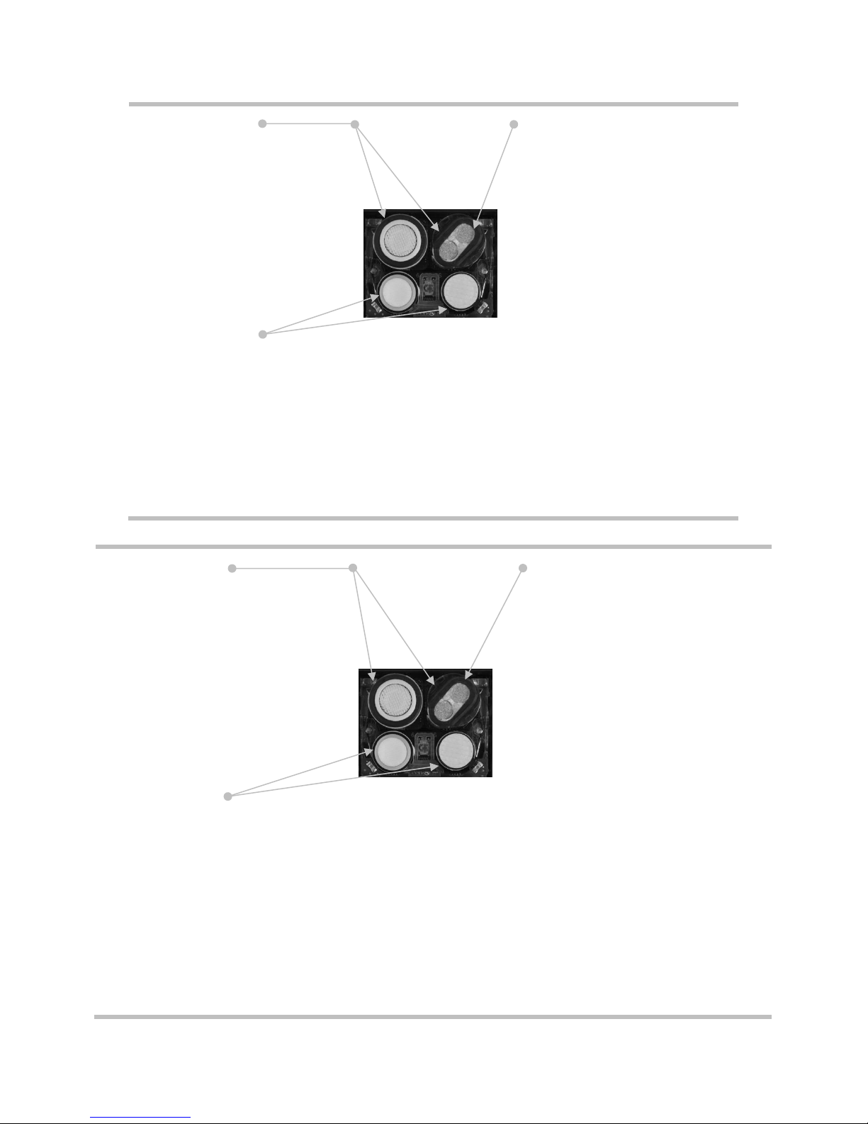
Each instrument’s compatible sensors can be installed in one or more specific locations as depicted in
Figures 2.1 and 2.2 for Ventis Pro4 and Ventis Pro5, respectively. Table 2.1 provides the same information
but in list format, which is helpful for distinguishing among sensors of the same type. For example, there
are two H2S sensors that do not share installation locations or part numbers.
9
Locations 1 or 2
Hydrogen Sulfide (H2S); 17155304-2
Oxygen (O2); 17155304-3
Location 2 only
LEL (Pentane); 17155304-K
LEL (Methane); 17155304-L
Methane, 0-5% vol; 17155304-M
Locations 3 or 4
Carbon Monoxide (CO); 17155306-1
Carbon Monoxide with low Hydrogen cross-sensitivity (CO/H2Low); 17155306-G
Hydrogen Cyanide (HCN); 17155306-B
Hydrogen Sulfide (H2S); 17155306-2
Nitrogen Dioxide (NO2); 17155306-4
Sulfur Dioxide (SO2); 17155306-5
Figure 2.1.A Sensor compatibility and installation locations for the Ventis Pro4
Locations 1 or 2
Carbon Monoxide/Hydrogen Sulfide
(CO/H2S); 17155304-J
Hydrogen Sulfide (H2S); 17155304-2
Oxygen (O2); 17155304-3
Location 2 only
Carbon Dioxide/Hydrocarbons (CO2/HC);
17155304-U
Carbon Dioxide/Methane (CO2/CH4);
17155304-V
LEL (Pentane); 17155304-K
LEL (Methane); 17155304-L
Methane, 0-5% vol; 17155304-M
Locations 3 or 4
Ammonia (NH3); 17155306-6
Carbon Monoxide (CO); 17155306-1
Carbon Monoxide/Hydrogen Sulfide (CO/H2S); 17155306-J
Carbon Monoxide with low Hydrogen cross-sensitivity (CO/H2Low); 17155306-G
Hydrogen Cyanide (HCN); 17155306-B
Hydrogen Sulfide (H2S); 17155306-2
Nitrogen Dioxide (NO2); 17155306-4
Sulfur Dioxide (SO2); 17155306-5)
Figure 2.1.B Sensor compatibility and installation locations for the Ventis Pro5

10
Table 2.1 Sensor compatibility and installation locations
Ventis
Pro4
Ventis
Pro5
Installation
locations
Part number
Sensor
Ammonia (NH3)
No
Yes
3 or 4
17155306-6
Carbon Dioxide/Hydrocarbons (CO2/HC)
No
Yes
2
17155304-U
Carbon Dioxide/Methane (CO2/CH4)
No
Yes
2
17155304-V
Carbon Monoxide (CO)
Yes
Yes
3 or 4
17155306-1
Carbon Monoxide/Hydrogen Sulfide
(CO/H2S)
No
Yes
1 or 2
17155304-J
Carbon Monoxide/Hydrogen Sulfide
(CO/H2S)*
No
Yes
3 or 4
17155306-J
Carbon Monoxide with low Hydrogen
cross-sensitivity (CO/H2Low)
Yes
Yes
3 or 4
17155306-G
Hydrogen Cyanide (HCN)
Yes
Yes
3 or 4
17155306-B
Hydrogen Sulfide (H2S)
Yes
Yes
1 or 2
17155304-2
Hydrogen Sulfide (H2S)
Yes
Yes
3 or 4
17155306-2
LEL (Methane)
Yes
Yes
2
17155304-L
LEL (Pentane)
Yes
Yes
2
17155304-K
Methane, 0-5% vol
Yes
Yes
2
17155304-M
Nitrogen Dioxide (NO2)
Yes
Yes
3 or 4
17155306-4
Oxygen (O2)*
Yes
Yes
1 or 2
17155304-3
Sulfur Dioxide (SO2)
Yes
Yes
3 or 4
17155306-5
*DualSense® technology capable.
Batteries
As shown below, the battery pack is compatible with the diffusion instrument only. The extended run-time
battery can be installed for use with a diffusion or aspirated instrument.
Table 2.2 Battery compatibility
Rechargeable Batteries
Part number
Lithium-ion battery pack
Extended-run-time Lithium-ion
battery
17134453
17148313
Compatibility
Ventis Pro Series diffusion
Yes
Yes
Ventis Pro Series aspirated
No
Yes

11
Specifications
Instrument
The Ventis Pro Series’ instrument specifications are provided below in Table 2.3.
Table 2.3 Instrument and pump specifications
Item
Description
Display
Monochrome LCD with automatic backlight
User interface buttons
Three (power button, enter button, and panic button)
Case materials
Polycarbonate with static-dissipative protective rubber overmold
Alarm signals
Visual (two red and two blue lights); audible (95 dB at a distance of 10 cm [3.94 "],
typicala); and vibration
Dimensions
104 x 58 x 36 mm (4.09 x 2.28 x 1 42 ")
Weight
200 g (7.05 oz.), typicalb
Ingress protection
IP68 at 1.5 m (4.9 ′) for one hour
Pump
With 0.3175 cm (0.125 ") inside diameter sample tubing, sustains a continuous sample
draw for up to 30.48 m (100 ').
Temperature rangec and d
-40°C to + 50 °C (-40 °F to + 122 °F)
Humidity ranged
15−95 % relative humidity (RH) noncondensing (continuous)
aMay vary based on in-field conditions.
bMay vary based on installed components.
cTemperatures below -20 °C (-4 °F), can diminish display-screen legibility and man-down functionality. See also "Cold-weather Operation"
(Chapter 1, "Recommended Practices") and Table 1.1, "Certifications".
dSensor temperature and humidity ranges may differ from those of the instrument (see "Table 2.5, Sensor specifications").

12
Battery Specifications
Table 2.4 provides battery specifications, which include run time, charge time, charging temperature
requirements, and expected lifetime.
Table 2.4 Battery specifications
Rechargeable Batteries
Part number
Lithium-ion battery pack
Extended-run-time Lithium-ion
battery
17134453
17148313
Llifetime
300 charge cycles
300 charge cycles
Run timea
12 hours
24 hours
Charge timeb
up to 4 hours
up to 7.5 hours
Ambient temperature required for
charging
0 − 40 °C (32 − 104 °F)
0 − 40 °C (32 − 104 °F)
aApproximate run time when the battery is fully charged and is operating at room temperature.
bWhen a lithium-ion battery or battery pack becomes deeply discharged and the instrument is docked, it can take up to an hour for the
instrument display to indicate that the battery is charging.
Sensor Specifications
Table 2.5 provides specifications for each sensor, which include properties, installation locations, operating
conditions, and performance, accuracy, and response-time data.

13
Table 2.5 Sensor specifications
Gas type (abbreviation)
Part number
Ammonia (NH3)
Carbon Dioxide/Hydrocarbons (CO2/HC)
17155306-6
17155304-Uc
Properties
Category
Toxic
Toxic/Combustible
Technology
Electrochemical
Infrared
DualSense™ capable
No
No
Installation location
Ventis Pro4
None
None
Ventis Pro5
3 or 4
2
Operating conditions
Temperature rangea
-20 to +40 °C (-4 to +104 °F)
-20 to +50 °C (-4 to +122 °F)
RH rangea
15-95%
0-95%
Performance
CO2
HC
Sensitivity
Measurement range
0−500 ppm
0-5% vol
0-100% LEL
Measurement resolution
1 ppm
0.01% vol
0.01% LEL
Accuracyc
Calibration gas and
concentration
50 ppm NH3
2.5% vol CO2
25% LEL Propane
Accuracy at time and
temperature of calibration
± 15% (0-100 ppm)
0 to 25% (101−500 ppm)
+10% or 0.1%
+5%
Accuracy over sensor’s full
temperature range
± 15%
+15%
+15%
Response Time
T50
30 s
17 s
17 s
T90
84 s
32 s
35 s

14
Table 2.5 Sensor specifications
Gas type (abbreviation)
Part number
Carbon Dioxide/Methane (CO2/CH4)
17155304-Vc
Properties
Category
Toxic and Combustible
Technology
Infrared
DualSense™ capable
No
Installation location
Ventis Pro4
None
Ventis Pro5
2
Operating conditions
Temperature rangea
-20 to +50 °C (-4 to +122 °F)
RH rangea
0-95%
Performance
CO2
CH4
Sensitivity
Measurement range
0−5% vol
0−5% vol
5.01-100% vol
Measurement resolution
0.01% vol
0.01% vol
0.1% vol
Accuracyc
Calibration gas and
concentration
2.5% vol CO2
2.5% vol
99% vol
Accuracy at time and
temperature of calibration
± 10%
± 10%
± 10%
Accuracy over sensor’s full
temperature range
± 15%
± 15%
__
Response Time
T50
17 s
15 s
15 s
T90
32 s
30 s
30 s
Other manuals for Ventis Pro Series
1
Table of contents
Other Industrial Scientific Security Sensor manuals


