Inficon Stripe CDG045Dhs User manual

2tina84e1-a (2019-07)
Product Identification
In all communications with INFICON, please specify the infor-
mation given on the product nameplate. For convenient refer-
ence copy that information into the space provided below.
Model:
PN:
SN:
VW
Validity
This document applies to products of the Stripe CDG045Dhs
series.
Part numbers of standard products are indicated below. OEM
products have other part numbers and different parameter
settings (e.g. factory setting of setpoint) as defined in the
corresponding ordering information.

tina84e1-a (2019-07) 3
The part number (PN) can be taken from the product nameplate.
If not indicated otherwise in the legends, the illustrations in this
document correspond to gauges with DN 16 ISO-KF vacuum
connection. They apply to gauges with other vacuum connec-
tions by analogy.
We reserve the right to make technical changes without prior
notice.

4tina84e1-a (2019-07)
Intended Use
The temperature compensated Capacitance Diaphragm Gauges
of the Stripe CDG045Dhs series are intended for absolute
pressure measurement of gases in their respective pressure
ranges (→2).
Ideally the measurement values can be read out digitally via
EtherCAT interface or analog. The gauges can also be operated
in connection with an INFICON Vacuum Gauge Controller (VGC
series) or another appropriate controller.
Functional Principle
A ceramic diaphragm is deflected by pressure. The deflection is
measured capacitively and converted into a digital or into an
analog linear output signal by the digital electronics. The digital
output signal can only be read out via the EthreCAT interface.
The output signal is independent of the gas type.
Very accurate pressure measurement is achieved by heating the
sensor to a constant temperature of 45°C which results in a com-
pensation of changes in the ambient conditions and a reduced
deposition of process products and by-products in process appli-
cations.
Trademarks
Stripe™INFICON GmbH
VCR®Swagelok Marketing Co.
Patents
EP 1070239 B1, 1040333 B1
US Patents 6528008, 6591687, 7107855, 7140085

tina84e1-a (2019-07) 5
Scope of Delivery
1× gauge Stripe CDG045Dhs
1× pin for adjusting settings via buttons
1× Calibration Test Report
1× Operating Manual German
1× Operating Manual English

6tina84e1-a (2019-07)
Contents
Product Identification 2
Validity 2
Intended Use 4
Functional Principle 4
Trademarks 4
Patents 4
Scope of Delivery 5
1Safety 8
1.1 Symbols Used 8
1.2 Personnel Qualifications 8
1.3 General Safety Instructions 9
1.4 Liability and Warranty 9
2Technical Data 10
3Installation 16
3.1 Vacuum Connection 16
3.2 Power Connection 19
3.2.1 D-sub, 15-pin Connector 20
3.2.2 EtherCAT Connector 21
3.2.3 Mini USB Type B Connector (Diagnostic Port) 22
4Operation 23
4.1 Status Indication 23
4.2 Zeroing the Gauge 24
4.2.1 <ZERO>Adjustment 24
4.3 Switching Functions SP1, SP2, ATM, Status 28
4.4 Activating the Factory Setting (Factory Reset) 34
4.7 Diagnostic Port (USB Interface) 35
4.8 EtherCAT Operation 35
5Deinstallation 37
6Maintenance, Repair 39

tina84e1-a (2019-07) 7
7Returning the Product 39
8Disposal 40
Further Information 41
EU Declaration of Conformity 43
For cross-references within this document, the symbol (→XY)
is used, for cross-references to further documents, listed under
"Further Information", the symbol (→[Z]).

8tina84e1-a (2019-07)
1 Safety
1.1 Symbols Used
DANGER
Information on preventing any kind of physical injury.
WARNING
Information on preventing extensive equipment and environ-
mental damage.
Caution
Information on correct handling or use. Disregard can lead to
malfunctions or minor equipment damage.
Notice
<…> Labeling
1.2 Personnel Qualifications
Skilled personnel
All work described in this document may only be carried out by
persons who have suitable technical training and the neces-
sary experience or who have been instructed by the end-user
of the product.

tina84e1-a (2019-07) 9
1.3 General Safety Instructions
•Adhere to the applicable regulations and take the necessary
precautions for the process media used.
Consider possible reactions with the product materials.
•Adhere to the applicable regulations and take the necessary
precautions for all work you are going to do and consider the
safety instructions in this document.
•Before beginning to work, find out whether any vacuum com-
ponents are contaminated. Adhere to the relevant regulations
and take the necessary precautions when handling contamin-
ated parts.
Communicate the safety instructions to all other users.
1.4 Liability and Warranty
INFICON assumes no liability and the warranty becomes null
and void if the end-user or third parties
•disregard the information in this document
•use the product in a non-conforming manner
•make any kind of interventions (modifications, alterations etc.)
on the product
•use the product with accessories not listed in the product
documentation.
The end-user assumes the responsibility in conjunction with the
process media used.
Gauge failures due to contamination are not covered by the
warranty.

10 tina84e1-a (2019-07)
2 Technical Data
Measurement range
→"Validity"
Precision
1)
0.01 … 0.05 F.S.
0.2% of reading
Accuracy 2)
0.1 … 1100 F.S.
0.15% of reading
Temperature effect on zero
0.01 … 0.02 F.S.
0.05 … 0.5 F.S.
1 … 1100 F.S.
0.0100% F.S./ °C
0.0050% F.S./ °C
0.0025% F.S./ °C
Temperature effect on span
0.01% of reading / °C
Resolution
0.003% F.S.
Gas type dependence
none
Output signal analog
(measurement signal)
Measurement range
0 … +10 V
Voltage range –5 … +10.5 V
(limited to +10.5 V)
Relationship voltage-pressure
linear
Output impedance
0 Ω(short-circuit proof)
Loaded impedance
>10 kΩ
Measurement rate
1 kHz
Step response time
3)
(analog output signal)
2 … 20 ms
4)
Delay time
(digital output signal, EtherCAT
interface)
2 ms
1) →ISO/WD 15725-1
2) Non-linearity, hysteresis, repeatability at 25 °C ambient operating
temperature without temperature effects after operation of 2 h.
3)Increase 10 … 90 % F.S.R.
4)Depending on pressure range, conductance vacuum connection and the
default filter setting.

tina84e1-a (2019-07) 11
Identification
Resistance RIdent
Voltage
13.2 kΩreferenced to sup-
ply common
≤5 V
Remote Zero Adjust digital input for zero adjust-
ment with external switching
contact (→24)
External switching contact
Pulse
30 V (dc) / <5 mA (dc)
>1 s … <5 s
Switching functions setpoints SP1& SP2, ATM,
status
Setpoints
Setting range SP1 & SP2
1 … 99% F.S.
Setting range ATM Factor 0.5 … 1.1 from ATM
pressure
Hysteresis 5)
1% F.S.
Switching characteristics
5)
Low Trip Point (default)
High Trip Point
Relay contact 30 V (dc) / ≤0.5 A (dc)
floating (NO)
closed
LED lit solid
open
LED off
Status relay
Relay contact 30 V (dc) / ≤0.5 A (dc)
connected to supply com-
mon (pin 5)
closed measurement mode
warning
open no supply voltage
warming up, error
Diagnostic port
Cable
Mini USB type B, 5-pin
USB cable type A/mini B
5)The hysteresis and the switching characteristics can be programmed via
the serial interface or the diagnostic port.

12 tina84e1-a (2019-07)
EtherCAT interface
Specification, data format,
communication protocol
3CC9-xxx-2380
3CC9-xxx-23G0
→[7], [8]
→[9], [10]
Data rate
100 Mbps
Note address
explicit device identification
Physical layer
100Base-Tx (IEEE 802.3)
EtherCAT connector 2×RJ45, 8-pin, socket
input and output
Cable 8-pin, shielded, Ethernet
Patch Cable (CAT5e quality
or higher)
Cable length
≤100 m
For further information on the EtherCAT interface →[5], [6]
Supply
DANGER
The gauge may only be connected to power sup-
plies, instruments or control devices that conform
to the requirements of a grounded protective extra-
low voltage (PELV). The connection to the gauge
has to be fused
6)
.
Supply voltage
at the gauge
+14 … +30 V (dc) or
±15 V (dc)
Power consumption
while being heated
at operating temperature
≤14 W
≤9 W
Fuse to be connected 6)
1.25 AT
The gauge is protected against reverse polarity of the supply
voltage and overload.
6) INFICON controllers fulfill this requirement.

tina84e1-a (2019-07) 13
Electrical connection
15-pin D-sub, male
Sensor cable
15-pin plus shielding
Cable length
Supply voltage 15 V
≤8 m (0.14 mm²/conductor)
≤15 m (0.25 mm²/conductor)
Supply voltage 24 V ≤43 m (0.14 mm²/conductor)
≤75 m (0.25 mm²/conductor)
Supply voltage 30 V ≤88 m (0.14 mm²/conductor)
≤135 m (0.25 mm²/conductor)
For longer cables, larger conductor cross-sections are required
(Rcable ≤1.0 Ω).
Grounding concept
→"Power Connection"
Materials exposed to vacuum ceramics (Al2O3≥99.5%),
stainless steel AISI 316L
Internal volume
≤4.2 cm3
Admissible pressure (absolute)
1000 / 1100 F.S.
1 … 500 F.S.
0.01 … 0.5 F.S.
4 bar | 400 kPa
2.6 bar | 260 kPa
1.3 bar | 130 kPa
Bursting pressure (absolute)
6 bar | 600 kPa
Admissible temperatures
Storage
Operation
Bakeout
–20 °C … +85 °C
+10 °C … +40 °C
≤110 °C at the flange
Relative humidity ≤80% at temperatures
≤+31 °C, decreasing to 50%
at +40°C
Use indoors only, altitude up to
3000 m NN
Degree of protection
IP 30
Mounting orientation
0.01 … 0.05 F.S.
0.1 … 1100 F.S.
standing upright or horizon-
tal
standing upright to horizon-
tal

14 tina84e1-a (2019-07)
Dimensions [mm]
15.7
31.5
110.4 3.8
DN 16 ISO-KF ½¨ tube
ø82
ø85
DN 16 CF-R
8VCR
female
Weight
837 … 897 g

tina84e1-a (2019-07) 15
Analog Measurement Signal vs. Pressure
1 2 3 4 5 6 7 8 9 10
0
0.9×F.S.
0.5×F.S.
0.6×F.S.
1.0×F.S.
0.7×F.S.
0.8×F.S.
0.1×F.S.
0.2×F.S.
0.3×F.S.
0.4×F.S.
1.1×F.S.
Pressure p
Measurement U
out
[V]
0.0×F.S.
p = (Uout / 10 V) × p (F.S.)
Conversion Torr ↔Pascal
Torr
mbar 7)
Pa 7
c 1.00 1013.25 / 760 =
1.3332…
101325 / 760 =
133.3224…
Example: Gauge with 10 Torr F.S.
Measurement signal Uout = 6 V
p = (6 V / 10 V) × 10 Torr
= 0.6 × 10 Torr = 6 Torr
7) Source: NPL (National Physical Laboratory)
Guide to the Measurement of Pressure and Vacuum, ISBN 0904457x /
1998

16 tina84e1-a (2019-07)
3 Installation
WARNING
Fragile components
The ceramic sensor may be damaged by impacts.
Do not drop the product and prevent shocks and
impacts.
3.1 Vacuum Connection
DANGER
Overpressure in the vacuum system >1 bar
Injury caused by released parts and harm caused
by escaping process gases can result if clamps are
opened while the vacuum system is pressurized.
Do not open any clamps while the vacuum system
is pressurized. Use the type clamps which are
suited to overpressure.
DANGER
Overpressure in the vacuum system >2.5 bar
KF flange connections with elastomer seals (e.g.
O-rings) cannot withstand such pressures. Process
media can thus leak and possibly damage your
health.
Use O-rings provided with an outer centering ring.

tina84e1-a (2019-07) 17
DANGER
Protective ground
Products that are not correctly connected to ground
can be extremely hazardous in the event of a fault.
Electrically connect the gauge to the grounded
vacuum chamber. This connection must conform to
the requirements of a protective connection ac-
cording to EN 61010:
•CF and VCR flanges fulfill this requirement.
•For gauges with a KF flange, use a conductive
metallic clamping ring.
•For gauges with a ½" tube, take appropriate
measures to fulfill this requirement.
Caution
Vacuum component
Dirt and damages impair the function of the vac-
uum component.
When handling vacuum components, take appro-
priate measures to ensure cleanliness and prevent
damages.
Caution
Dirt sensitive area
Touching the product or parts thereof with bare
hands increases the desorption rate.
Always wear clean, lint-free gloves and use clean
tools when working in this area.
Mount the gauge so that no vibrations occur.

18 tina84e1-a (2019-07)
Mounting orientation
0.01 … 0.05 F.S.
standing upright or
horizontal acc. to the
"Calibration Test
Report"
0.1 … 1100 F.S.
standing upright to
horizontal
If adjustment should be possible after the gauge has been in-
stalled, be sure to install it so that the buttons can be accessed
with a pin.
Remove the protective lid and connect the product to the vac-
uum system.
Seal with
centering ring
Clamp
Protective lid
Keep the protective lid.

tina84e1-a (2019-07) 19
3.2 Power Connection
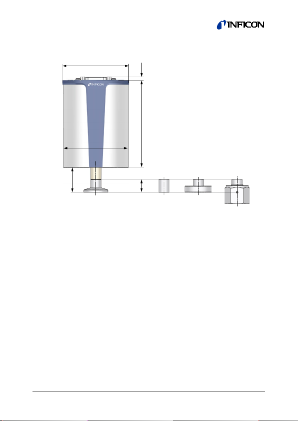
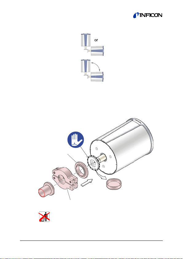
Make sure the vacuum connection is properly made
(→16).
DANGER
The gauge may only be connected to power sup-
plies, instruments or control devices that conform
to the requirements of a grounded protective extra-
low voltage (PELV) The connection to the gauge
has to be fused
8)
.
Ground loops, differences of potential, or EMC problems
may affect the measurement signal. For optimum signal
quality, please do observe the following notes:
•Use an overall metal braided shielded cable. The
connector must have a metal case.
•Connect the cable shield to ground at one side via the
connector case. Make sure the connector case has
direct contact to the cable's shield on its whole cir-
cumference. Do not connect the other side of the
shield.
•Connect the supply common with protective ground
directly at the power.
•Use differential measurement input (signal common
and supply common conducted separately).
•Potential difference between supply common and
housing ≤18 V (overvoltage protection).
8) INFICON controllers fulfill this requirement.

20 tina84e1-a (2019-07)
3.2.1 D-sub, 15-pin Connector
If no sensor cable is available, make one according to the
following diagram (cable length and conductor cross-sections
→13).
case
14…30 V
Remote
Zero Adjust
1M
4
3
1
8
9
10
Ident13
14
2
12
7
11
5
15
680 nF
18 V
10 Ω
6
SP1
SP2
Status
Electrical connection
Pin 1, 4
Relay SP1, closing contact
15 8
91
D-sub, 15-pin
female
soldering side
Pin 2
Signal output (measuring
signal) or thresholds SP1/2
Pin 3
Status
Pin 5
Supply common
Pin 7, 11
Supply (+14…+30 V)
Pin 8, 9
Relay SP2, closing contact
Pin 10
Gauge identification or
Remote Zero Adjust
Pin 12
Signal common
Pin 15
Housing (Chassis Ground)
Case
Connector case
Pin 6, 13, 14: n.c.
Table of contents
Other Inficon Industrial Equipment manuals
Popular Industrial Equipment manuals by other brands

Yoshitake
Yoshitake Trap Star TSF-13 manual

Aeroex Technologies
Aeroex Technologies ROX-400 Installation & service manual

schmalenberger
schmalenberger FLUVO xanas 1,5 Operator's manual

Siemens
Siemens SIMATIC Power Line Booster operating instructions

Woodward
Woodward CPC-DX Installation and operation manual

Emerson
Emerson Yarway Installation, operation and maintenance instructions

power knot
power knot LFC-100 quick start guide

Mitsubishi
Mitsubishi SAF Series user manual

Finn
Finn MTS SR Parts and Operator's Manual

Zimmer
Zimmer GEH8000 Series Installation and operating instructions

Maprox
Maprox CHUCK 3 ZF ultra-short Operating instruction

Eaton
Eaton 2596 Installation, operation & service manual